air conditioning SKODA YETI 2012 1.G / 5L Owner's Manual
[x] Cancel search | Manufacturer: SKODA, Model Year: 2012, Model line: YETI, Model: SKODA YETI 2012 1.G / 5LPages: 225, PDF Size: 5.47 MB
Page 5 of 225
Table of Contents
Abbreviations
Using the system
Cockpit 7
Overview 6
Instruments and Indicator Lights 8
Instrument Cluster 8
Multifunction display (onboard computer) 12
MAXI DOT (information display) 15
Indicator lights 18
Unlocking and locking 26
Vehicle key 26
Child safety lock 27
Central locking system 27
Remote control 30
Anti-theft alarm system 31
Boot lid 33
Electric power windows 34
Panoramic sliding roof 36
Lights and visibility 39
Lights 39
Interior light 46
Visibility 47
Windscreen wipers and washers 48
Rear window 52
Seats and Stowage 55
Front seats 55
Head restraints 59
Rear seats 60
Boot 62
Variable loading floor in the boot 66Variable loading floor with spare wheel 68
Roof rack system 68
Cup holder 69
Ashtray 70
Cigarette lighter, 12-volt power socket 71
Storage compartments 72
Through-loading bag 78
Clothes hooks 78
Parking ticket holder 79
Heating and air conditioning system 80
Heating and air conditioning system 80
Air outlet vents 81
Heating 82
Air conditioning system (manual air conditioning
system) 83
Climatronic (automatic air conditioning
system) 86
Auxiliary heating (auxiliary heating and
ventilation) 88
Starting-off and Driving 92
Starting and stopping the engine 92
Brakes and brake assist systems 94
OFF ROAD mode 98
Shifting (manual gearbox) 100
Pedals 100
Parking aid 100
Park assist 101
Cruise control system (CCS) 104
START/STOP 106
Fatigue detection system (break
recommendation) 107
Automatic gearbox 109
Automatic gearbox 109
Communication 114
Mobile phones and two-way radio systems 114
Operating the phone on the multifunction
steering wheel 115Symbols in the information display 116
Phone Phonebook 116
Universal telephone preinstallation GSM II 116
Universal telephone preinstallation GSM IIl 119
Voice control 123
Multimedia 125
Safety
Passive Safety 128
General information 128
Correct seated position 129
Seat belts 132
Seat belts 132
Airbag system 137
Description of the airbag system 137
Front airbags 138
Driver’s knee airbag 139
Side airbags 140
Head airbags 141
Deactivating airbags 141
Transporting children safely 143
Child seat 143
Driving Tips
Driving and the Environment 146
The first 1 500 km 146
Catalytic converter 146
Economical and environmentally friendly
driving 147
Environmental compatibility 149
Driving abroad 150
Avoiding damage to your vehicle 150
3
Table of Contents
Page 9 of 225
Using the system
Cockpit
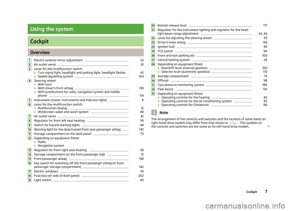
Overview
Electric exterior mirror adjustment 53
Air outlet vents 81
Lever for the multifunction switch:
› Turn signal light, headlight and parking light, headlight flasher 45
› Speed regulating system 104
Steering wheel:
› With horn
› With driver’s front airbag 138
› With pushbuttons for radio, navigation system and mobile
phone 114
Instrument cluster: Instruments and indicator lights 8
Lever for the multifunction switch:
› Multifunction display 12
› Windscreen wiper and wash system 48
Air outlet vents 81
Regulator for front left seat heating 58
Switch for hazard warning lights 44
Warning light for the deactivated front seat passenger airbag 142
Storage compartment on the dash panel 73
Depending on equipment fitted:
› Radio
› Navigation system
Regulator for front right seat heating 58
Storage compartment on the front passenger side 72
Front passenger airbag 138
Key switch for switching off the front passenger airbag (in front
passenger storage compartment) 142
Electric windows 34
Fuse box (on side of dash panel) 202
Light switch 401
2
3
4
5
6
7
8
9
10
11
12
13
14
15
16
17
18
19 Bonnet release lever 171
Regulator for the instrument lighting and regulator for the head-
light beam range adjustment 43, 44
Lever for adjusting the steering wheel 93
Driver’s knee airbag 139
Ignition lock 94
TCS switch 94
Front and rear parking aid 100
Central locking system 29
Depending on equipment fitted:
› Gearshift lever (manual gearbox) 100
› Selector lever (automatic gearbox) 110
Storage compartment 73
Offroad 98
Tyre pressure monitoring system 186
Park Assist 101
Depending on equipment fitted:
› Operating controls for the heating 82
› Operating controls for the air conditioning system 83
› Operating controls for Climatronic 86
Note
The arrangement of the controls and switches and the location of some items on
right-hand drive models may differ from that shown in »
Fig. 1. The symbols on
the controls and switches are the same as for left-hand drive models. Ð 20
21
22
23
24
25
26
27
28
29
30
31
32
33
7
Cockpit
Page 36 of 225
There is a risk of unwanted entry into the vehicle before the boot lid is locked au-
tomatically. Always lock the vehicle using the button on the remote control or
with the key if no remote control is available » page 29 .ÐEmergency unlocking
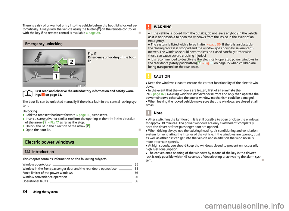
Fig. 17
Emergency unlocking of the boot
lid
First read and observe the introductory information and safety warn-
ings on page 33.
The boot lid can be unlocked manually if there is a fault in the central locking sys-
tem.
Unlocking
›
Fold the rear seat backrest forward
» page 60, Rear seats.
› Insert a screwdriver or similar tool into the opening in the trim in the direction
of the arrow 1
» Fig. 17
as far as the stop.
› Unlock the lid in the direction of the arrow 2
.
› Open the boot lid. ÐElectric power windows
ä
Introduction
This chapter contains information on the following subjects:
Window open/close 35
Window in the front passenger door and the rear doors open/close 35
Force limiter of the power windows 36
Window convenience operation 36
Operational faults 36
ä WARNING
■ If the vehicle is locked from the outside, do not leave anybody in the vehicle
as it is not possible to open the windows from the inside in the event of an
emergency.
■ The system is fitted with a force limiter » page 36. If there is an obstacle,
the closing process is stopped and the window goes down by several centi-
metres. The windows should nevertheless be closed carefully! Otherwise
these can cause severe crushing injuries!
■ It is recommended to deactivate the electrically operated power windows in
the rear doors (safety pushbutton) S
» Fig. 18 on page 35 when children are
being transported on the rear seats. CAUTION
■ Keep the windows clean to ensure the correct functionality of the electric win-
dows. ■ In the event that the windows are frozen, first of all eliminate the
ice » page 163, De-icing windows and exterior mirrors and only then operate the
power windows otherwise the power window mechanism could be damaged. ■ When leaving the locked vehicle make sure that the windows are closed at all
times. Note
■ After switching the ignition off, it is still possible to open or close the windows
for approx. 10
minutes. The power windows are only switched off completely
once the driver or front passenger door are opened. ■ When driving always use the existing heating, air conditioning and ventilation
system for ventilating the interior of the vehicle. If the windows are opened, dust
as well as other dirt can get into the vehicle and in addition the wind noise is
more at certain speeds.
■ At high speeds, you should keep the windows closed to prevent unnecessarily
high fuel consumption.
■ The convenience opening of the windows by means of the key in the driver's
lock is only possible within 45
seconds of deactivating or activating the alarm sys-
tem. Ð
34 Using the system
Page 75 of 225
Cooling the storage compartment on the front passenger side
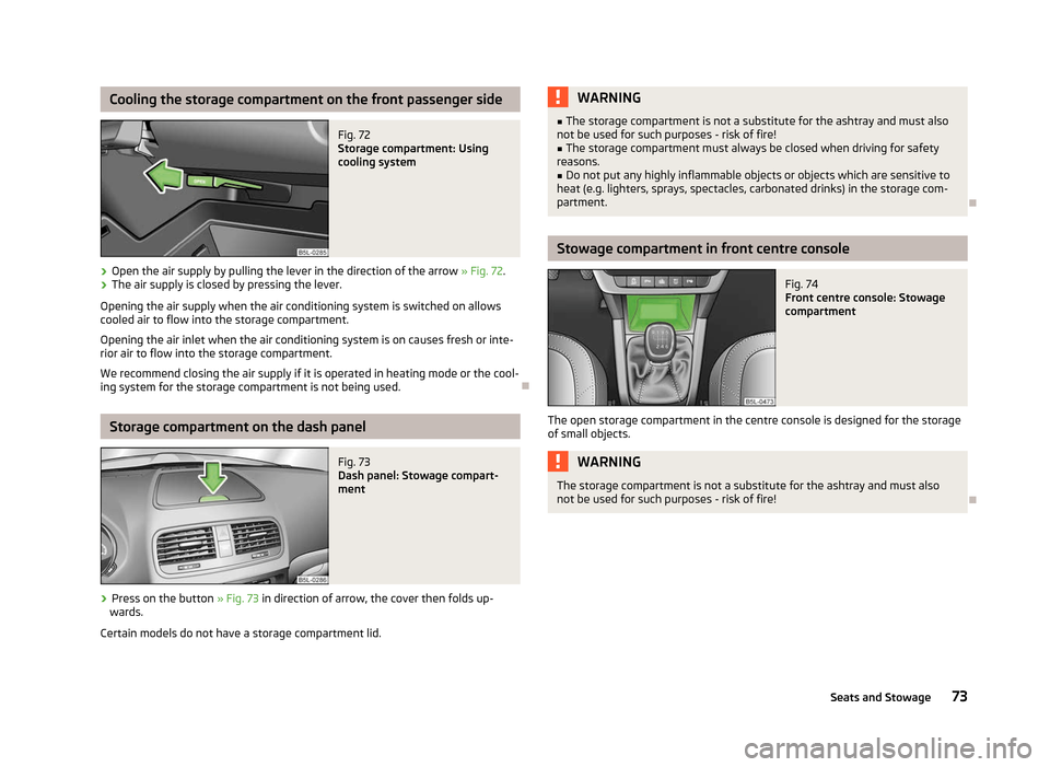
Fig. 72
Storage compartment: Using
cooling system
› Open the air supply by pulling the lever in the direction of the arrow
» Fig. 72.
› The air supply is closed by pressing the lever.
Opening the air supply when the air conditioning system is switched on allows
cooled air to flow into the storage compartment.
Opening the air inlet when the air conditioning system is on causes fresh or inte-
rior air to flow into the storage compartment.
We recommend closing the air supply if it is operated in heating mode or the cool-
ing system for the storage compartment is not being used. ÐStorage compartment on the dash panel
Fig. 73
Dash panel: Stowage compart-
ment
› Press on the button
» Fig. 73 in direction of arrow, the cover then folds up-
wards.
Certain models do not have a storage compartment lid. WARNING
■ The storage compartment is not a substitute for the ashtray and must also
not be used for such purposes - risk of fire!
■ The storage compartment must always be closed when driving for safety
reasons.
■ Do not put any highly inflammable objects or objects which are sensitive to
heat (e.g. lighters, sprays, spectacles, carbonated drinks) in the storage com-
partment. Ð Stowage compartment in front centre console
Fig. 74
Front centre console: Stowage
compartment
The open storage compartment in the centre console is designed for the storage
of small objects. WARNING
The storage compartment is not a substitute for the ashtray and must also
not be used for such purposes - risk of fire! Ð
73
Seats and Stowage
Page 77 of 225
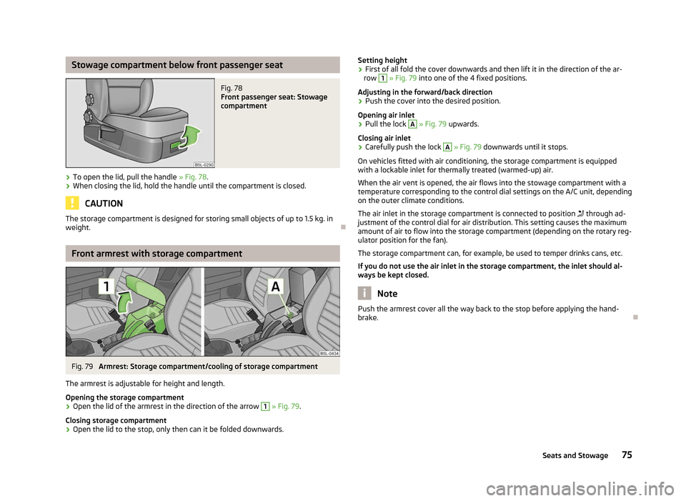
Stowage compartment below front passenger seat
Fig. 78
Front passenger seat: Stowage
compartment
› To open the lid, pull the handle
» Fig. 78.
› When closing the lid, hold the handle until the compartment is closed. CAUTION
The storage compartment is designed for storing small objects of up to 1.5 kg. in
weight. ÐFront armrest with storage compartment
Fig. 79
Armrest: Storage compartment/cooling of storage compartment
The armrest is adjustable for height and length.
Opening the storage compartment
› Open the lid of the armrest in the direction of the arrow 1
» Fig. 79.
Closing storage compartment
› Open the lid to the stop, only then can it be folded downwards. Setting height
› First of all fold the cover downwards and then lift it in the direction of the ar-
row 1
» Fig. 79 into one of the 4 fixed positions.
Adjusting in the forward/back direction
› Push the cover into the desired position.
Opening air inlet
› Pull the lock A
» Fig. 79 upwards.
Closing air inlet
› Carefully push the lock A
» Fig. 79 downwards until it stops.
On vehicles fitted with air conditioning, the storage compartment is equipped
with a lockable inlet for thermally treated (warmed-up) air.
When the air vent is opened, the air flows into the stowage compartment with a
temperature corresponding to the control dial settings on the A/C unit, depending
on the outer climate conditions.
The air inlet in the storage compartment is connected to position through ad-
justment of the control dial for air distribution. This setting causes the maximum
amount of air to flow into the storage compartment (depending on the rotary reg-
ulator position for the fan).
The storage compartment can, for example, be used to temper drinks cans, etc.
If you do not use the air inlet in the storage compartment, the inlet should al-
ways be kept closed. Note
Push the armrest cover all the way back to the stop before applying the hand-
brake. Ð
75
Seats and Stowage
Page 82 of 225
Heating and air conditioning system
Heating and air conditioning system
Introductory information
The heating effect is dependent upon the coolant temperature, thus full heat
output only occurs when the engine has reached its operating temperature.
If the cooling system is switched on, the temperature and air humidity drops in
the vehicle. The well-being of the occupants of the car is enhanced as a result of
this particularly at high outside temperatures and a high air humidity. The system
prevents the windows misting up during the cold season of the year.
It is possible to briefly activate recirculated air mode to enhance the cooling ef-
fect.
Please refer to the information regarding recirculated air mode for the air-condi-
tioning system » page 85 or for Climatronic »
page 87.
The air inlet in front of the windscreen must be free of ice, snow or leaves to en-
sure that the heating and cooling system operates properly.
After switching on the cooling Condensation from the evaporator of the air condi-
tioning may drip down and form a puddle below the vehicle. This is quite normal
and not an indication of a leak! WARNING
■ For your own safety and that of other road users, ensure that all the win-
dows are free of ice, snow and misting. Please familiarize yourself about how
to correctly operate the heating and ventilation systems, how to demist and
defrost the windows, as well as with the cooling mode.
■ Do not leave recirculated air mode on over a longer period of time, as “stale”
air can cause fatigue of the driver and passengers, reduce attention levels and
also cause the windows to mist up. The risk of having an accident increases.
Switch off recirculated air mode as soon as the windows start to mist up. Note
■ The used air streams out through the vents in the boot.
■ We recommend that you do not smoke in the vehicle when the recirculating air
mode is operating since the smoke which is drawn at the evaporator from the in-
terior of the vehicle forms deposits in the evaporator of the air conditioning sys-
tem. This produces a permanent odour when the air conditioning system is oper-
ating which can only be eliminated through considerable effort and expense (re-
placement of compressor). ■ To ensure that the heating and air conditioning systems work properly, do not
block up the air outlet vents with any objects. Ð Using the air conditioning system economically
The compressor on the air conditioning system uses power from the engine when
in cooling mode which will effect the fuel consumption.
It recommended to open the windows or the doors of a vehicle for which the inte-
rior has been strongly heated through the effect of direct sunlight in order to al-
low the heated air to escape.
The cooling system should not be switched on while travelling when the window
is open.
If the desired interior temperature can also be achieved without activating the
cooling system, fresh air mode should be selected. For the sake of the environment
Pollutant emissions are also reduced when fuel is saved. Ð Operational problems
If the cooling system does not operate at outside temperatures higher than +5 °C,
there is a problem in the system. The reasons for this may be.
› One of the fuses has blown. Check the fuse and replace if necessa-
ry »
page 201 .
› The cooling system has switched off automatically for a short time because the
coolant temperature of the engine is too hot
» page 9.
If you cannot rectify the functional fault yourself, or the cooling capacity decrea-
ses, the cooling system must be switched off. Visit a ŠKODA specialist garage. Ð
80 Using the system
Page 83 of 225
Air outlet vents
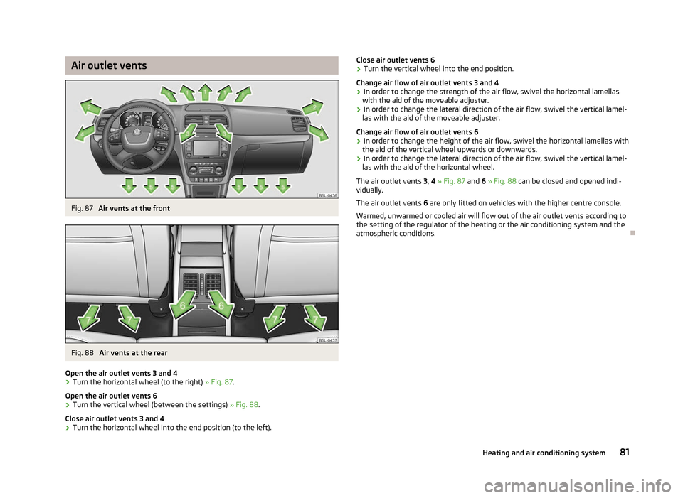
Fig. 87
Air vents at the front Fig. 88
Air vents at the rear
Open the air outlet vents 3 and 4
› Turn the horizontal wheel (to the right)
» Fig. 87.
Open the air outlet vents 6
› Turn the vertical wheel (between the settings)
» Fig. 88.
Close air outlet vents 3 and 4
› Turn the horizontal wheel into the end position (to the left). Close air outlet vents 6
› Turn the vertical wheel into the end position.
Change air flow of air outlet vents 3 and 4
› In order to change the strength of the air flow, swivel the horizontal lamellas
with the aid of the moveable adjuster.
› In order to change the lateral direction of the air flow, swivel the vertical lamel-
las with the aid of the moveable adjuster.
Change air flow of air outlet vents 6
› In order to change the height of the air flow, swivel the horizontal lamellas with
the aid of the vertical wheel upwards or downwards.
› In order to change the lateral direction of the air flow, swivel the vertical lamel-
las with the aid of the horizontal wheel.
The air outlet vents 3, 4 » Fig. 87 and 6 »
Fig. 88 can be closed and opened indi-
vidually.
The air outlet vents 6 are only fitted on vehicles with the higher centre console.
Warmed, unwarmed or cooled air will flow out of the air outlet vents according to
the setting of the regulator of the heating or the air conditioning system and the
atmospheric conditions. Ð
81
Heating and air conditioning system
Page 85 of 225

Set-up
Setting of the control dial
Button 1
Air outlet vents 4
A B C
The fastest heating
To the right up to the
stop 3
Briefly switch on
Opening
Comfortable heating Desired temperature 2 or 3
Do not switch on
Opening
Fresh air mode - ventilation To the left up to the
stop Desired position
Do not switch on
OpeningNote
■ Controls A
, B
, C
and the button 1
» Fig. 89
on page 82.
■ Air outlet vents 4 » Fig. 87 on page 81.
■ We recommend that you leave the air outlet vents 3 » Fig. 87 on page 81 in the
opened position. ÐRecirculated air mode
Recirculated air mode prevents polluted air outside the vehicle from getting into
the vehicle, for example when driving through a tunnel or when standing in a
traffic jam.
Switching on
› Press the button
» Fig. 89
on page 82 and the indicator light in the button
illuminates.
Switching off
› Press the button
» Fig. 89
on page 82again - the indicator light in the but-
ton goes out.
Recirculated air mode is switched off automatically if the air distribution control C
is turned to position
» Fig. 89 on page 82. Recirculated air mode can be
switched on again from this setting by repeatedly pressing the button .
WARNING
Do not leave recirculated air mode on over a longer period of time, as “stale”
air can cause fatigue of the driver and passengers, reduce attention levels and
also cause the windows to mist up. The risk of having an accident increases.
Switch off recirculated air mode as soon as the windows start to mist up. Ð Air conditioning system (manual air conditioning
system) Introductory information
The cooling system only operates if the button AC 1
» Fig. 90 on page 84
is
pressed, and the following conditions are met:
› engine running;
› outside temperature above approx. +2 °C;
› blower switch switched on (positions 1 to 4).
Under certain circumstances, air at a temperature of about 5 °C can flow out of
the vents when the cooling system is switched on. Lengthy and uneven distribu-
tion of the air flow out of the vents and large differences in temperature, for ex-
ample when getting out of the vehicle, can result in chills in sensitive persons. Note
We recommend that you have the air conditioning system cleaned by a ŠKODA
specialist garage once every year. Ð
83
Heating and air conditioning system
Page 86 of 225

Using the system
Fig. 90
The air conditioning system: Control elements
Setting temperature
› Turn the control dial A
» Fig. 90 to the right to increase the temperature.
› Turn the control dial A
to the left to decrease the temperature.
Controlling blower
› Turn the blower switch B
» Fig. 90 into one of the positions, 1 to 4, to switch
the blower on.
› Turn the blower switch B
into position 0 to switch the blower off.
› Press the button
4
to close the fresh air supply
» Fig. 90.
Regulating the air distribution
› The direction of the inlet air flow is controlled with air distribution regulator C
» Fig. 90
» page 81, Air outlet vents .
Switching the cooling system on and off
› Press the button
AC 1
» Fig. 90 . The indicator light lights up in the button.
› When you again press the button
AC , the air conditioning system is switched
off. The indicator light in the button goes out.
Rear window heater › Press the button
2
» Fig. 90
. Further information » page 47, Windscreen
and rear window heater . Auxiliary heating (parking heating)
›
Press the button
3
»
Fig. 90
to directly switch on/off the auxiliary heating
(auxiliary heating and ventilation). Further information » page 88, Auxiliary
heating (auxiliary heating and ventilation) . Note
■ The whole heat output will be needed to defrost the windscreen and side win-
dows. No warm air will be fed to the footwell. This can lead to restriction of the
heating comfort. ■ The indicator light AC » Fig. 90
lights after activation, even if not all of the con-
ditions for the function of the cooling system have been met » page 83, Introduc-
tory information . By lighting up of the indicator light in the button, the operation-
al readiness of the cooling system is signalled. Ð84
Using the system
Page 87 of 225

Setting the air conditioning system
Recommended basic settings of the control elements of the air conditioning sys-
tem for the respective operating modes:
Set-up Setting of the control dial
Button
Air outlet vents 4 A B C 1 4
Defrost/defog windscreen and
side windows
a) Desired tempera-
ture 3 or 4
Automatically
switched on Do not switch on Open and align with the side
window
The fastest heating To the right up to
the stop 3
Switched off Briefly switch on
Opening
Comfortable heating Desired tempera-
ture 2 or 3
Switched off Do not switch on
Opening
The fastest cooling To the left up to
the stop briefly 4, then
2 or 3 Activated Briefly switch on
Opening
Optimal cooling Desired tempera-
ture 1, 2 or 3
Activated Do not switch on Open and align to the roof
Fresh air mode - ventilation To the left up to
the stop Desired position
Switched off Do not switch on
Openinga)
We recommend that you do not use this setting in countries with high humidity levels. This can result in heavy cooling of the window glass and the following fogging from outside. Note
■ Controls A
, B
, C
and the button 1
and 4
» Fig. 90 on page 84
.
■ Air outlet vents 4 » Fig. 87 on page 81 .
■ We recommend that you leave the air outlet vents 3 » Fig. 87 on page 81 in the
opened position. ÐRecirculated air mode
Recirculated air mode prevents polluted air outside the vehicle from getting into
the vehicle, for example when driving through a tunnel or when standing in a
traffic jam.
Switching on
› Press the button
4
» Fig. 90
on page
84 and the indicator light in the but-
ton illuminates. Switching off
›
Press the button
again - the indicator light in the button goes out.
Recirculated air mode is switched off automatically if the air distribution control C
» Fig. 90
on page
84 is turned to position
. Recirculated air mode can be
switched on again from this setting by repeatedly pressing the button .
WARNING
Do not leave recirculated air mode on over a longer period of time, as “stale”
air can cause fatigue of the driver and passengers, reduce attention levels and
also cause the windows to mist up. The risk of having an accident increases.
Switch off recirculated air mode as soon as the windows start to mist up. Ð
85
Heating and air conditioning system