instrument cluster SKODA YETI 2012 1.G / 5L Owner's Manual
[x] Cancel search | Manufacturer: SKODA, Model Year: 2012, Model line: YETI, Model: SKODA YETI 2012 1.G / 5LPages: 225, PDF Size: 5.47 MB
Page 5 of 225
Table of Contents
Abbreviations
Using the system
Cockpit 7
Overview 6
Instruments and Indicator Lights 8
Instrument Cluster 8
Multifunction display (onboard computer) 12
MAXI DOT (information display) 15
Indicator lights 18
Unlocking and locking 26
Vehicle key 26
Child safety lock 27
Central locking system 27
Remote control 30
Anti-theft alarm system 31
Boot lid 33
Electric power windows 34
Panoramic sliding roof 36
Lights and visibility 39
Lights 39
Interior light 46
Visibility 47
Windscreen wipers and washers 48
Rear window 52
Seats and Stowage 55
Front seats 55
Head restraints 59
Rear seats 60
Boot 62
Variable loading floor in the boot 66Variable loading floor with spare wheel 68
Roof rack system 68
Cup holder 69
Ashtray 70
Cigarette lighter, 12-volt power socket 71
Storage compartments 72
Through-loading bag 78
Clothes hooks 78
Parking ticket holder 79
Heating and air conditioning system 80
Heating and air conditioning system 80
Air outlet vents 81
Heating 82
Air conditioning system (manual air conditioning
system) 83
Climatronic (automatic air conditioning
system) 86
Auxiliary heating (auxiliary heating and
ventilation) 88
Starting-off and Driving 92
Starting and stopping the engine 92
Brakes and brake assist systems 94
OFF ROAD mode 98
Shifting (manual gearbox) 100
Pedals 100
Parking aid 100
Park assist 101
Cruise control system (CCS) 104
START/STOP 106
Fatigue detection system (break
recommendation) 107
Automatic gearbox 109
Automatic gearbox 109
Communication 114
Mobile phones and two-way radio systems 114
Operating the phone on the multifunction
steering wheel 115Symbols in the information display 116
Phone Phonebook 116
Universal telephone preinstallation GSM II 116
Universal telephone preinstallation GSM IIl 119
Voice control 123
Multimedia 125
Safety
Passive Safety 128
General information 128
Correct seated position 129
Seat belts 132
Seat belts 132
Airbag system 137
Description of the airbag system 137
Front airbags 138
Driver’s knee airbag 139
Side airbags 140
Head airbags 141
Deactivating airbags 141
Transporting children safely 143
Child seat 143
Driving Tips
Driving and the Environment 146
The first 1 500 km 146
Catalytic converter 146
Economical and environmentally friendly
driving 147
Environmental compatibility 149
Driving abroad 150
Avoiding damage to your vehicle 150
3
Table of Contents
Page 9 of 225
Using the system
Cockpit
Overview
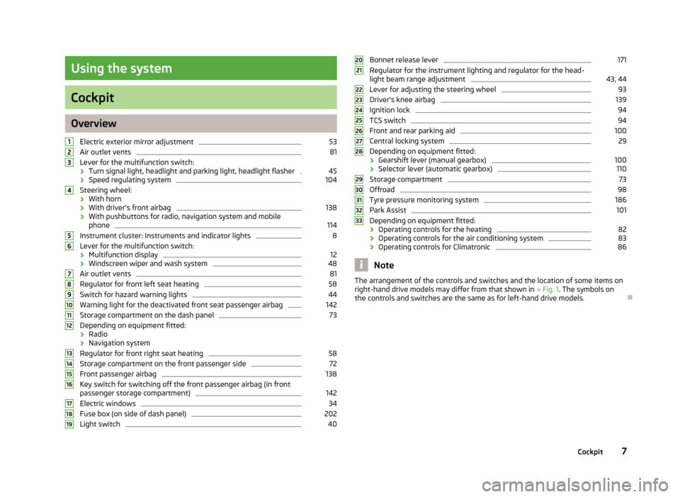
Electric exterior mirror adjustment 53
Air outlet vents 81
Lever for the multifunction switch:
› Turn signal light, headlight and parking light, headlight flasher 45
› Speed regulating system 104
Steering wheel:
› With horn
› With driver’s front airbag 138
› With pushbuttons for radio, navigation system and mobile
phone 114
Instrument cluster: Instruments and indicator lights 8
Lever for the multifunction switch:
› Multifunction display 12
› Windscreen wiper and wash system 48
Air outlet vents 81
Regulator for front left seat heating 58
Switch for hazard warning lights 44
Warning light for the deactivated front seat passenger airbag 142
Storage compartment on the dash panel 73
Depending on equipment fitted:
› Radio
› Navigation system
Regulator for front right seat heating 58
Storage compartment on the front passenger side 72
Front passenger airbag 138
Key switch for switching off the front passenger airbag (in front
passenger storage compartment) 142
Electric windows 34
Fuse box (on side of dash panel) 202
Light switch 401
2
3
4
5
6
7
8
9
10
11
12
13
14
15
16
17
18
19 Bonnet release lever 171
Regulator for the instrument lighting and regulator for the head-
light beam range adjustment 43, 44
Lever for adjusting the steering wheel 93
Driver’s knee airbag 139
Ignition lock 94
TCS switch 94
Front and rear parking aid 100
Central locking system 29
Depending on equipment fitted:
› Gearshift lever (manual gearbox) 100
› Selector lever (automatic gearbox) 110
Storage compartment 73
Offroad 98
Tyre pressure monitoring system 186
Park Assist 101
Depending on equipment fitted:
› Operating controls for the heating 82
› Operating controls for the air conditioning system 83
› Operating controls for Climatronic 86
Note
The arrangement of the controls and switches and the location of some items on
right-hand drive models may differ from that shown in »
Fig. 1. The symbols on
the controls and switches are the same as for left-hand drive models. Ð 20
21
22
23
24
25
26
27
28
29
30
31
32
33
7
Cockpit
Page 10 of 225
Instruments and Indicator Lights
Instrument Cluster
ä
Introduction
This chapter contains information on the following subjects:
Overview 8
Engine revolutions counter 9
Speedometer 9
Coolant temperature gauge 9
Fuel gauge 9
Counter for distance driven 10
Service Interval Display 10
Digital clock 11
Recommended gear 11
WARNING
■ Concentrate fully at all times on your driving! As the driver you are fully re-
sponsible for the operation of your vehicle.
■ Never operate the controls in the instrument cluster while driving, only
when the vehicle is stationary! Ð Overview
Fig. 2
Instrument cluster
First read and observe the introductory information and safety warn-
ings on page 8.
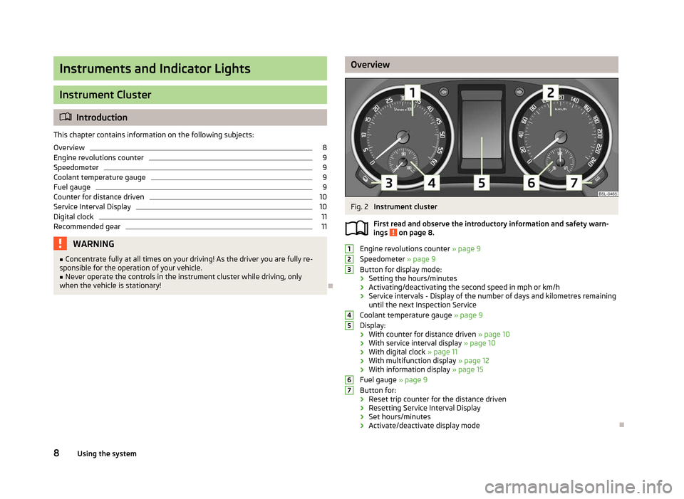
Engine revolutions counter
» page 9
Speedometer » page 9
Button for display mode:
› Setting the hours/minutes
› Activating/deactivating the second speed in mph or km/h
› Service intervals - Display of the number of days and kilometres remaining
until the next Inspection Service
Coolant temperature gauge » page 9
Display:
› With counter for distance driven
» page 10
› With service interval display
» page 10
› With digital clock
» page 11
› With multifunction display
» page 12
› With information display » page 15
Fuel gauge » page 9
Button for:
› Reset trip counter for the distance driven
› Resetting Service Interval Display
› Set hours/minutes
› Activate/deactivate display mode Ð
ä 1
2
3
4
5
6
7
8
Using the system
Page 11 of 225
Engine revolutions counter
First read and observe the introductory information and safety warn-
ings on page 8.
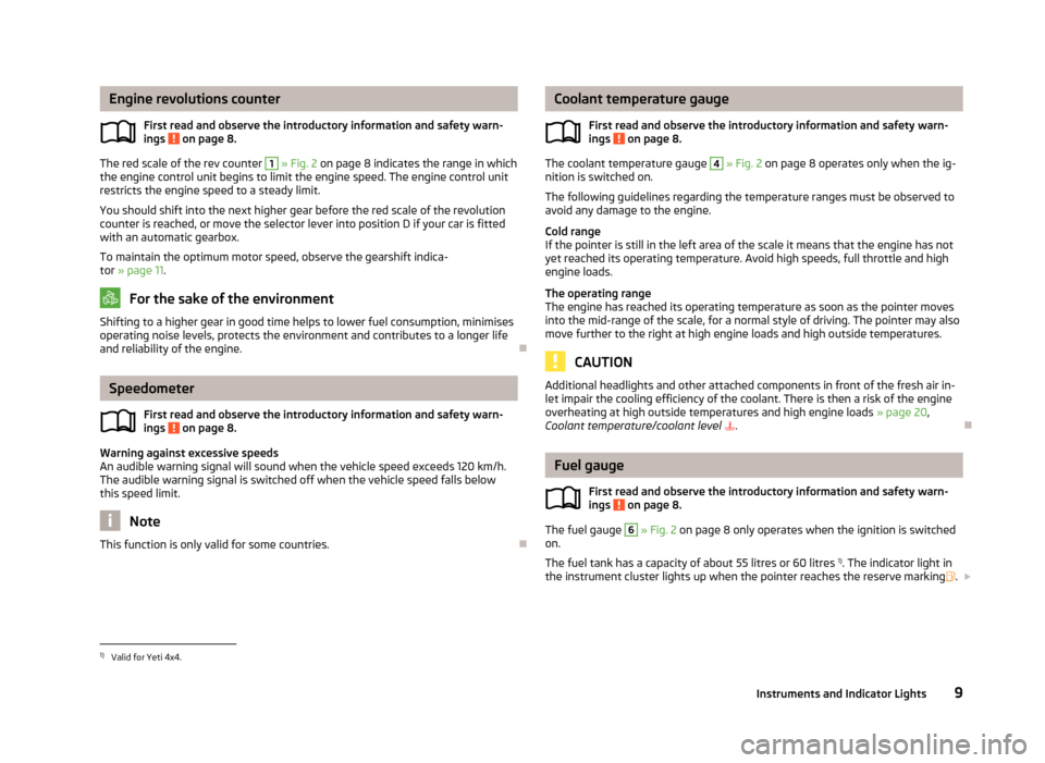
The red scale of the rev counter 1
» Fig. 2 on page 8 indicates the range in which
the engine control unit begins to limit the engine speed. The engine control unit
restricts the engine speed to a steady limit.
You should shift into the next higher gear before the red scale of the revolution
counter is reached, or move the selector lever into position D if your car is fitted
with an automatic gearbox.
To maintain the optimum motor speed, observe the gearshift indica-
tor » page 11. For the sake of the environment
Shifting to a higher gear in good time helps to lower fuel consumption, minimises
operating noise levels, protects the environment and contributes to a longer life
and reliability of the engine. ÐSpeedometer
First read and observe the introductory information and safety warn-
ings on page 8.
Warning against excessive speeds
An audible warning signal will sound when the vehicle speed exceeds 120 km/h.
The audible warning signal is switched off when the vehicle speed falls below
this speed limit.
Note
This function is only valid for some countries. Ð
ä
ä Coolant temperature gauge
First read and observe the introductory information and safety warn-
ings on page 8.
The coolant temperature gauge 4
» Fig. 2 on page 8 operates only when the ig-
nition is switched on.
The following guidelines regarding the temperature ranges must be observed to
avoid any damage to the engine.
Cold range
If the pointer is still in the left area of the scale it means that the engine has not
yet reached its operating temperature. Avoid high speeds, full throttle and high
engine loads.
The operating range
The engine has reached its operating temperature as soon as the pointer moves
into the mid-range of the scale, for a normal style of driving. The pointer may also
move further to the right at high engine loads and high outside temperatures. CAUTION
Additional headlights and other attached components in front of the fresh air in-
let impair the cooling efficiency of the coolant. There is then a risk of the engine
overheating at high outside temperatures and high engine loads »
page 20,
Coolant temperature/coolant level . Ð Fuel gauge
First read and observe the introductory information and safety warn-
ings on page 8.
The fuel gauge 6
» Fig. 2 on page 8 only operates when the ignition is switched
on.
The fuel tank has a capacity of about 55 litres or 60 litres 1)
. The indicator light in
the instrument cluster lights up when the pointer reaches the reserve marking .£
ä
ä
1)
Valid for Yeti 4x4.
9
Instruments and Indicator Lights
Page 12 of 225

CAUTION
Never drive until the fuel tank is completely empty! An irregular supply of fuel can
lead to irregular engine running. Unburnt fuel may get into the exhaust system
and damage the catalytic converter. Note
After filling up, it can occur that during dynamic driving (e.g. numerous curves,
braking, driving downhill and climbing a steep hill) the fuel gauge indicates ap-
prox. a fraction less. When stopping or during less dynamic driving, the fuel gauge
displays the correct fuel level again. This is not a fault. ÐCounter for distance driven
First read and observe the introductory information and safety warn-
ings on page 8.
The distance which you have driven with your vehicle is shown in kilometres (km).
In some countries the measuring unit (mph) is used.
Daily trip counter (trip)
The daily trip counter indicates the distance which you have driven since it was
last reset - in steps of 100 metres or 1/10 of a mile.
To reset the display of the daily trip counter, press button
7
» Fig. 2 on page 8
for longer.
Odometer
The odometer indicates the total distance in kilometres or miles which the vehicle
has been driven.
Fault display
If there is a fault in the instrument cluster Error will appear continuously in the
display. Ensure the fault is rectified as soon as possible by
ŠKODA a specialist ga-
rage. Note
For vehicles fitted with the information display, if the display of the second speed
is activated in mph or km/h, this driving speed is indicated instead of the counter
for the total distance driven. Ð
ä Service Interval Display
Fig. 3
Service Interval Display: Note
First read and observe the introductory information and safety warn-
ings on page 8.
The display can vary depending on the equipment.
Service Interval Display
Before the next service interval a key symbol
and the remaining kilometres are
indicated for 10 seconds after switching on the ignition » Fig. 3. At the same time,
the remaining days until the next service interval are displayed.
The following is displayed in the information display: Service in ... km or ... days.
The kilometre indicator or the days indicator reduces in steps of 100
km or, where
applicable, days until the service due date is reached.
As soon as the due date for the service is reached, a flashing key symbol and
the text Service appears in the display for 20 seconds after the ignition has been
switched on.
The following is displayed in the information display:
Service now!
Displaying the distance and days until the next service interval
You can use the button 3
to display the remaining distance and days until the
next service interval » Fig. 2 on page 8
.
A key symbol and the remaining distance appear for 10 seconds in the display.
At the same time, the remaining days until the next service interval are displayed.
On vehicles which are equipped with the information display, you can call up this
display in the menu Settings » page 16. £
ä
10 Using the system
Page 13 of 225
The following will be displayed in the information display for 10
seconds:
Service in ... km or ... days.
Resetting Service Interval Display
It is only possible to reset the Service Interval Display, if a service message or at
least a pre-warning is shown in the instrument cluster display.
We recommend that this reset is completed by a
ŠKODA specialist garage.
The ŠKODA specialist garage: › Resets the memory of the display after the appropriate inspection
› Adds an entry to the Service Schedule
› Affixes the sticker with the entry of the following service interval to the side of
the dashboard on the driver's side
Reset the service interval display by using the reset button 7
»
Fig. 2 on page 8.
On vehicles which are equipped with the information display, you can reset the
Service Interval Display in the menu Settings » page 16.CAUTION
We recommend that you do not reset the Service Interval Display yourself as this
can result in the incorrect setting of the Service Interval Display, which can also
cause possible problems with the operation of your vehicle. Note
■ Never reset the display between service intervals, as this will result in the incor-
rect display. ■ Information is retained in the Service Interval Display even after the vehicle bat-
tery is disconnected.
■ If the instrument cluster is exchanged after a repair, the correct values must be
entered in the counter for the Service Interval Display. This work is carried out by
a ŠKODA specialist garage. ■ After resetting the display with flexible service intervals, the displayed data is
the same as that for a vehicle with fixed service intervals. We therefore recom-
mend that the Service Interval Display is only reset by a
ŠKODA Service Partner,
who will reset the display with a vehicle system tester. ■ For more information on the service intervals » Service Plan. Ð Digital clock
First read and observe the introductory information and safety warn-
ings on page 8.
The clock is set with the buttons 3
and 7
» Fig. 2 on page 8.
Select the display that you wish to change with the button 3
and carry out the
change with the button 7
.
On vehicles that are fitted with the information display, it is also possible to set
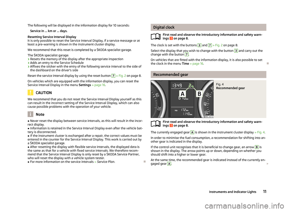
the clock in the menu Time » page 16. Ð Recommended gear
Fig. 4
Recommended gear
First read and observe the introductory information and safety warn-
ings on page 8.
The currently engaged gear A
is shown in the instrument cluster display
» Fig. 4.
In order to minimise the fuel consumption, a recommendation for shifting into an-
other gear is indicated in the display.
If the control unit recognises that it is beneficial to change gear, an arrow B
is
shown in the display. The arrow points up or down, depending on whether you
should shift into a higher or lower gear.
At the same time, the recommended gear is indicated instead of the currently en-
gaged gear A
.
£
ä
ä
11
Instruments and Indicator Lights
Page 19 of 225
Mirror adjust.
Switch on/off the function for left and right exterior
mirror setting simultaneously.
Factory setting Restore the Convenience factory setting.a)
This function is only available on vehicles with a rain sensor.
b) This function is only available on vehicles with an electrically adjustable driver seat.
Lights and visibility
This is where the following functions can be activated, deactivated or adjusted:
Coming Home Switch on/off and adjust the light duration of the Com-
ing Home function.
Leaving Home Switch on/off and adjust the light duration of the Com-
ing Home function.
Dayl. dri. light Switch on/off the “DAY LIGHT” function.
Rear wiper Switch on/off the function for automatic rear window
wiping.
Lane ch. flash Switch on/off the convenience flashing function.
Travel mode Switch on/off the travel model function.
Factory setting Restore the factory setting for the lighting.Time
The time, time format (12 or 24 hour indicator) and the changeover between sum-
mer/winter time can be set here.
Winter tyres
Here, you can set the speed at which an audible signal should sound. This func-
tion is, for example, used for winter tyres where the maximum permissible speed
is lower than the maximum speed of the vehicle.
When exceeding the speed, the following is shown on the information display:
Winter tyres:
max. speed ... km/h
Units of measurement
The units for the temperature, consumption and distance driven can be set here.
Assistants
The tones of the audible signals for the parking aid can be adjusted here. Second speed
The display of the second speed in mph or in km/h can be switched on here.
Service
Here you can have the remaining kilometres and days until the next service inter-
val displayed, and reset the Service Interval Display.
Factory setting
After selecting the menu Factory setting
the factory setting of the information
display is restored. Ð Door, boot lid and bonnet warning
First read and observe the introductory information and safety warn-
ings on page 15.
If at least one door is open, or the boot or bonnet is open, the information display
indicates the relevant
open door or boot/bonnet.
An audible signal also sounds if the vehicle is travelling at more than 6
km/h.Ð Auto Check Control
First read and observe the introductory information and safety warn-
ings on page 15.
Vehicle condition
Certain functions and conditions of individual vehicle systems are checked contin-
uously when the ignition is switched on and also while driving.
Some error messages and other information are displayed in the information dis-
play. The messages are displayed at the same time as the symbols in the informa-
tion display or the indicator lights in the instrument cluster » page 18.
If there is at least one error message, the menu item Vehicle status is displayed
in the menu. After selecting this menu the first of the error messages is dis-
played. Several error messages are shown on the display under the message e.g.
1/3. This indicates that the first of a total of three error messages is being dis-
played. £
ä
ä
17
Instruments and Indicator Lights
Page 30 of 225
If the ignition key is withdrawn, the car is then automatically unlocked again. In
addition, it is possible for the driver or front passenger to unlock the car by press-
ing the central locking button » page 29.
The doors can be unlocked and opened from the inside by a single pull on the
opening lever of the respective door. WARNING
Locked doors prevent unwanted entry into the vehicle from outside, for exam-
ple at road crossings. Locked doors do, however, make it more difficult for res-
cuers to get into the vehicle in an emergency - danger to life! Note
■ You can have the individual settings activated by a ŠKODA Service Partner or
you can activate them yourself with the help of the information display » page 16,
Settings. ■ In the event of an accident in which the airbags are deployed, the locked doors
are automatically unlocked in order to enable rescuers to gain access to the vehi-
cle. ■ Only the driver's door can be unlocked or locked using the key if the central
locking system fails » page 28. The other doors and the boot lid can be manually
locked or unlocked. ■ Emergency locking of the door » page 32.
■ Emergency unlocking of the boot lid » page 34. ÐSafe securing system
The central locking system is equipped with a safe securing system. The door
locks are blocked automatically if the vehicle is locked from the outside. The indi-
cator light flashes for around 2 seconds in quick succession, afterwards it begins
to flash evenly at longer intervals. It is not possible to open the doors with the
door handle either from the inside or from the outside. This acts as an effective
deterrent for attempts to break into your vehicle.
The safe securing system can be deactivated within 2
seconds by double locking
the vehicle.
If the safe securing system is not operating, the warning light in the driver door
flashes for about 2 seconds fast, goes out and starts to flash evenly at longer in-
tervals after about 30 seconds. The safe securing system is activated again the next time the vehicle is unlocked
and locked.
If the vehicle is locked and the safe securing system is deactivated, the door can
be opened from the inside by a single pull on opening lever of the respective
door.
WARNING
If the vehicle is locked from the outside and the safe securing system is acti-
vated, there must not be any person in the vehicle as it is then no longer pos-
sible to open either a door or a window from the inside. The locked doors
make it more difficult for rescuers to get into the vehicle in an emergency -
hazard! Note
■ The anti-theft alarm system is activated when the vehicle is locked even if the
safe securing system is deactivated. The interior monitor is however not activa-
ted. ■ After locking the vehicle, you will be informed that the safe securing system is
activated by means of the message CHECK DEADLOCK on the instrument cluster
display. On vehicles that are equipped with an information display, the following
message will appear Check deadlock! Owner's manual! appears.Ð Unlocking the vehicle using the key
Fig. 11
Turning the key for unlocking
and locking the vehicle
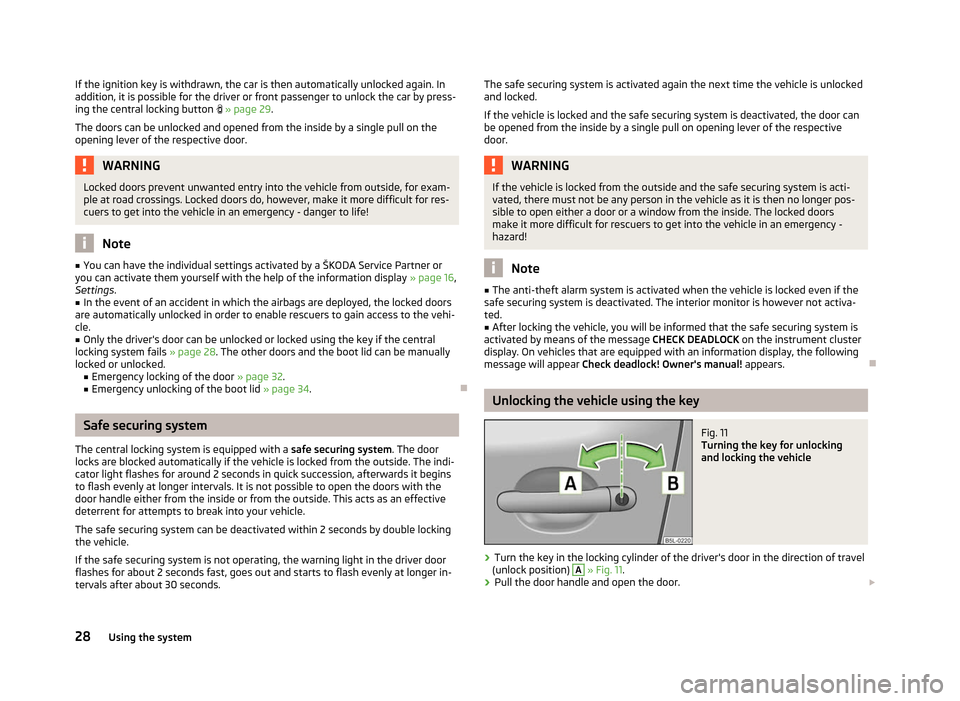
› Turn the key in the locking cylinder of the driver's door in the direction of travel
(unlock position) A
» Fig. 11.
› Pull the door handle and open the door.
£
28 Using the system
Page 42 of 225
Switching lights on and off
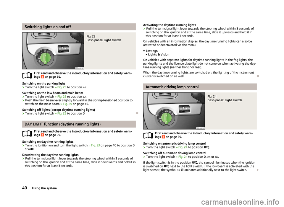
Fig. 23
Dash panel: Light switch
First read and observe the introductory information and safety warn-
ings on page 39.
Switching on the parking light
› Turn the light switch
» Fig. 23 to position .
Switching on the low beam and main beam
› Turn the light switch
» Fig. 23 to position .
› Push the main beam lever slightly forward in the spring-tensioned position to
switch on the main beam » Fig. 29 on page 45.
Switching off lights (except daytime running lights)
› Turn the light switch
» Fig. 23 to position 0. ÐDAY LIGHT function (daytime running lights)
First read and observe the introductory information and safety warn-
ings on page 39.
Switching on daytime running lights
› Turn the ignition on and turn the light switch
» Fig. 23 on page 40 to position 0
or .
Deactivating the daytime running lights
› Pull the turn signal light lever towards the steering wheel within 3
seconds of
switching on the ignition and at the same time, slide it downwards and hold it in
this position for at least 3
seconds.
ä
ä Activating the daytime running lights
› Pull the turn signal light lever towards the steering wheel within 3
seconds of
switching on the ignition and at the same time, slide it upwards and hold it in
this position for at least 3
seconds.
On vehicles with an information display, the daytime running lights can also be
activated or deactivated via the menu:
■ Settings
■ Lights & Vision
On vehicles with separate lights for daytime running lights in the fog lights, the
parking lights and the licence plate light do not come on when activating the day-
time running lights (neither front nor rear).
When the daytime running lights are switched on, the lighting of the instrument
cluster is switched on as well. Ð Automatic driving lamp control
Fig. 24
Dash panel: Light switch
First read and observe the introductory information and safety warn-
ings on page 39.
Switching on automatic driving lamp control
› Turn the light switch
» Fig. 24 to position
.
Switching off automatic driving lamp control
› Turn the light switch
» Fig. 24 to position 0, or .
If the light switch is in the position , the symbol illuminates when the ignition
is switched on next to the light switch. If the low beam is activated with the
light sensor, the symbol illuminates additionally next to the light switch. £
ä
40 Using the system
Page 44 of 225

The COMING HOME/LEAVING HOME function is controlled with the light sensor in
the mount of the interior rear mirror. If the light intensity is higher than the set
value of the light sensor, the light is not switched on after opening the driver's
door or unlocking the vehicle with the radio remote control.
Switching off the
COMING HOME function
The light goes out 10 seconds after closing all of the doors and the boot lid.
If a door or the boot lid remains open, the light goes out after 60 seconds.
Switching off the LEAVING HOME function
The light goes out 10 seconds after unlocking the vehicle with the radio remote
control, switching on the ignition or locking the vehicle.
If no door is opened, the vehicle is locked automatically after 30 seconds.Note
■ If the
COMING HOME/LEAVING HOME function is switched on constantly, the
battery will be heavily discharged particularly over short distances. ■ The illumination period for the COMING HOME/LEAVING HOME function can be
changed by means of the information display. ÐTourist light
First read and observe the introductory information and safety warn-
ings on page 39.
Xenon headlight
This mode makes it possible to drive in countries with opposing traffic system,
driving on the left/right, without dazzling the oncoming vehicles. When the mode
“tourist light
” is active, the side to side swivel of the headlights is deactivated.
The “tourist light” mode is activated/deactivated via the information display in
the menu: ■ Settings
■ Lights & Vision
■ Travel mode
■ Off
■ Switched on
Halogen headlight
When using Halogen headlights, it is necessary to stick a sticker over a certain
part of the headlights in order to prevent the dazzling of oncoming traffic.
ä You can purchase headlight stickers from the range of the ŠKODA original acces-
sories.
Ð Fog lights
Fig. 25
Dash panel: Light switch
First read and observe the introductory information and safety warn-
ings on page 39.
Switching on
› First of all, turn the light switch
» Fig. 25 to position or .
› Pull the light switch to position 1
.
The indicator light lights up in the instrument cluster when the fog lights are
switched on » page 18. Ð Fog lights with the function CORNER
First read and observe the introductory information and safety warn-
ings on page 39.
The fog lights with the function CORNER are designed to improve the illumination
of the surrounding area near the vehicle when turning, parking, etc. £
ä
ä
42 Using the system