brake light SKODA YETI 2013 1.G / 5L Owner's Manual
[x] Cancel search | Manufacturer: SKODA, Model Year: 2013, Model line: YETI, Model: SKODA YETI 2013 1.G / 5LPages: 266, PDF Size: 26.71 MB
Page 6 of 266
Table of Contents
Materials defect liability and ŠKODA warranty for
new cars5
Mobility warranty and ŠKODA extended
warranty
6
Abbreviations
Using the system
Cockpit
9
Overview
8
Instruments and Indicator Lights
10
Instrument cluster
10
Warning lights
14
Information system
23
Driver information system
23
Multifunction display (MFD)
25
MAXI DOT display
28
Service interval display
30
Unlocking and opening
32
Unlocking and locking
32
KESSY
38
Anti-theft alarm system
39
Luggage compartment lid
40
Electric power windows
41
Panorama sliding/tilting roof
44
Lights and visibility
47
Lights
47
Interior lights
53
Visibility
55
Windscreen wipers and washers
56
Rear mirror
58Seats and useful equipment61Front seats61
Front seat functions
64
Head restraints
66
Rear seats
67
Practical equipment
70
Luggage compartment
81
Variable loading floor in the luggage
compartment (Estate)
88
Roof rack system
90
Heating and air-conditioning
91
Heating, ventilation, cooling
91
Auxiliary heating (auxiliary heating and ventilation)
97
Communication and multimedia
100
General information
100
Universal telephone preinstallation GSM II
103
Universal telephone preinstallation GSM IIl
105
Wi-Fi
109
Voice control
110
Multimedia
113
Driving
Starting-off and Driving
117
Steering
117
Starting and stopping the engine using the
key
118
Starting and stopping the engine - KESSY
120
Brakes
124
Manual gear changing and pedals
125
Automatic transmission
126
Running in
129
Economical driving and environmental
sustainability
130
Water crossing and drive outside paved roads
134
Driving abroad
135Assist systems136Brake assist systems136
OFF ROAD-mode
138
Parking aid
140
Optical Parking Assist (Rear view camera)
141
Park assist
143
Cruise Control System
147
START-STOP
149
Fatigue detection (break recommendation)
151
Towing a trailer
152
Towing device
152
Trailer
156
Safety
Passive Safety
160
General information
160
Correct seated position
161
Seat belts
164
Using seat belts
164
Inertia reels and belt tensioners
167
Airbag system
169
Description of the airbag system
169
Airbag overview
170
Deactivating airbags
175
Transporting children safely
177
Child seat
177
Fastening systems
180
General Maintenance
Vehicle care
182
Service intervals
182
Service work, adjustments and technical alterations
184
Washing your car
1873Table of Contents
Page 7 of 266
Taking care of your vehicle exterior189Taking care of the interior192
Inspecting and replenishing
196
Fuel
196
Engine compartment
199
Engine oil
202
Coolant
204
Brake fluid
206
Vehicle battery
207
Wheels
212
Tyres and wheel rims
212
Winter operation
217
Do-it-yourself
Emergency equipment and self-help
219
Emergency equipment
219
Changing a wheel
221
Tyre repair
224
Jump-starting
226
Towing the vehicle
228
Remote control and removable light
230
Emergency unlocking/locking
232
Emergency operation of the sliding/tilting roof
234
Replacing windscreen wiper blades
234
Fuses and light bulbs
236
Fuses
236
Bulbs
238
Technical data
Technical data
244
Vehicle data
244
Index
4Table of Contents
Page 10 of 266
AbbreviationsAbbreviationDefinitionrpmEngine revolutions per minuteABSAnti-lock brake systemAFMulti-purpose vehiclesAPNAccess Point Name - the name of an access point for the WiFinetworkTCSTraction controlCO 2 in g/kmdischarged quantity of carbon dioxide in grams per driven kilo-
meterDPFDiesel particle filterDSGAutomatic double clutch gearboxDSRActive driver-steering recommendationEDLElectronic differential lockECEEconomic Commission for EuropeEPCEPC fault lightESCElectronic Stability ControlEUEuropean UnionGSMGroupe Spécial Mobile - a digital network of mobile devices for the transmission of voice and dataHFPHands-free profile - connection of a mobile device by means of
its Bluetooth ®
profilekWKilowatt, measuring unit for the engine outputMGManual gearboxMFDMultifunction displayN1Panel van intended exclusively or mainly for the transporta-
tion of goodsNmNewton meter, measuring unit for the engine torquePINPersonal Identification Number - personal identification num- ber for the connection of electronic devices using Bluetooth ®
or WiFirSAPRemote SIM Access Profile - remote transmission of SIM dataAbbreviationDefinitionSSPsimple security pairing - connection of two devices using Blue-
tooth ®
profileTDI CRDiesel engine with turbocharging and common rail injection
systemTSATrailer stabilisationTSIPetrol engine with turbocharging and direct injectionUMTSUniversal Mobile Telecommunication System - the next evolu- tion of the GSM network (3G)WLANWireless Local Area Network - wireless connection of elec-
tronic devices for data transfer (WiFi)
7Abbreviations
Page 12 of 266
Using the system
Cockpit
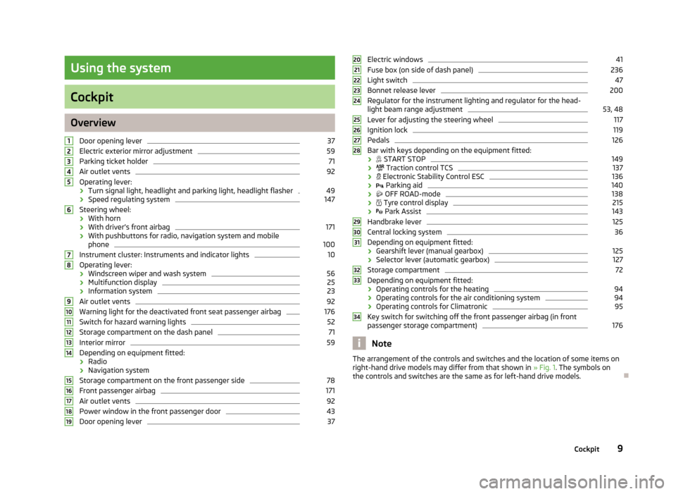
OverviewDoor opening lever
37
Electric exterior mirror adjustment
59
Parking ticket holder
71
Air outlet vents
92
Operating lever:
› Turn signal light, headlight and parking light, headlight flasher
49
›Speed regulating system
147
Steering wheel:
› With horn
› With driver’s front airbag
171
›With pushbuttons for radio, navigation system and mobile
phone
100
Instrument cluster: Instruments and indicator lights
10
Operating lever:
› Windscreen wiper and wash system
56
›Multifunction display
25
›Information system
23
Air outlet vents
92
Warning light for the deactivated front seat passenger airbag
176
Switch for hazard warning lights
52
Storage compartment on the dash panel
71
Interior mirror
59
Depending on equipment fitted:
› Radio
› Navigation system
Storage compartment on the front passenger side
78
Front passenger airbag
171
Air outlet vents
92
Power window in the front passenger door
43
Door opening lever
3712345678910111213141516171819Electric windows41Fuse box (on side of dash panel)236
Light switch
47
Bonnet release lever
200
Regulator for the instrument lighting and regulator for the head- light beam range adjustment
53, 48
Lever for adjusting the steering wheel
117
Ignition lock
119
Pedals
126
Bar with keys depending on the equipment fitted:
›
START STOP
149
›
Traction control TCS
137
›
Electronic Stability Control ESC
136
›
Parking aid
140
›
OFF ROAD-mode
138
›
Tyre control display
215
›
Park Assist
143
Handbrake lever
125
Central locking system
36
Depending on equipment fitted:
› Gearshift lever (manual gearbox)
125
›
Selector lever (automatic gearbox)
127
Storage compartment
72
Depending on equipment fitted:
› Operating controls for the heating
94
›Operating controls for the air conditioning system
94
›
Operating controls for Climatronic
95
Key switch for switching off the front passenger airbag (in front
passenger storage compartment)
176
Note
The arrangement of the controls and switches and the location of some items on
right-hand drive models may differ from that shown in » Fig. 1. The symbols on
the controls and switches are the same as for left-hand drive models.2021222324252627282930313233349Cockpit
Page 17 of 266
The menu item Vehicle status is shown in the main menu of the MAXI DOT dis-
play whenever at least one fault message exists. After selecting this menu, the
first of the error messages is displayed. Several error messages are shown on the
display under the message e.g. 1/3. This indicates that the first of a total of three
error messages is being displayed.
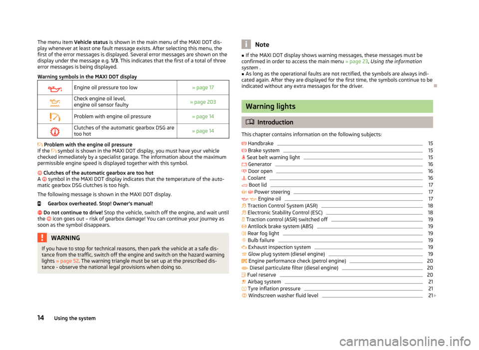
Warning symbols in the MAXI DOT displayEngine oil pressure too low» page 17Check engine oil level,
engine oil sensor faulty» page 203Problem with engine oil pressure» page 14Clutches of the automatic gearbox DSG are too hot» page 14
Problem with the engine oil pressure
If the
symbol is shown in the MAXI DOT display, you must have your vehicle
checked immediately by a specialist garage. The information about the maximum
permissible engine speed is displayed together with this symbol.
Clutches of the automatic gearbox are too hot
A
symbol in the MAXI DOT display indicates that the temperature of the auto-
matic gearbox DSG clutches is too high.
The following message is shown in the MAXI DOT display. Gearbox overheated. Stop! Owner's manual!
Do not continue to drive! Stop the vehicle, switch off the engine, and wait until
the
icon goes out – risk of gearbox damage! You can continue your journey as
soon as the symbol disappears.
WARNINGIf you have to stop for technical reasons, then park the vehicle at a safe dis- tance from the traffic, switch off the engine and switch on the hazard warning
lights » page 52 . The warning triangle must be set up at the prescribed dis-
tance - observe the national legal provisions when doing so.Note■ If the MAXI DOT display shows warning messages, these messages must be
confirmed in order to access the main menu » page 23, Using the information
system .■
As long as the operational faults are not rectified, the symbols are always indi-
cated again. After they are displayed for the first time, the symbols continue to be
indicated without any extra messages for the driver.
Warning lights
Introduction
This chapter contains information on the following subjects:
Handbrake
15
Brake system
15
Seat belt warning light
15
Generator
16
Door open
16
Coolant
16
Boot lid
17
Power steering
17
Engine oil
17
Traction Control System (ASR)
18
Electronic Stability Control (ESC)
18
Traction control (ASR) switched off
19
Antilock brake system (ABS)
19
Rear fog light
19
Bulb failure
19
Exhaust inspection system
19
Glow plug system (diesel engine)
19
Engine performance check (petrol engine)
20
Diesel particulate filter (diesel engine)
20
Fuel reserve
20
Airbag system
21
Tyre inflation pressure
21
Windscreen washer fluid level
21
14Using the system
Page 18 of 266
Turn signal system21 Fog lights22
Cruise control system
22
Selector lever lock
22
OFF ROADmode
22
Main beam
22
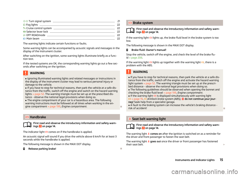
The warning lights indicate certain functions or faults.
Some warning lights can be accompanied by acoustic signals and messages in the
display of the instrument cluster.
After switching on the ignition, some warning lights illuminate briefly as a func-
tion test.
If the tested systems are OK, the corresponding warning lights go out a few sec-
onds after switching on the ignition.
WARNING■ Ignoring illuminated warning lights and related messages or instructions in
the display of the instrument cluster may lead to serious personal injury or
damage to the vehicle.■
If you have to stop for technical reasons, then park the vehicle at a safe dis-
tance from the traffic, switch off the engine and switch on the hazard warning lights » page 52 . The warning triangle must be set up at the prescribed dis-
tance - observe the national legal provisions when doing so.
■
The engine compartment of your car is a hazardous area. The following
warning instructions must be followed at all times when working in the en-
gine compartment » page 199, Engine compartment .
Handbrake
First read and observe the introductory information and safety warn-
ings
on page 14.
The indicator light
comes on if the handbrake is applied.
An acoustic signal will sound if you drive the vehicle above 6 km/h for at least 3
seconds while the handbrake is applied.
The following message is shown in the MAXI DOT display. Release parking brake!
Brake system
First read and observe the introductory information and safety warn-
ings
on page 14.
If the warning light lights up, the brake fluid level in the brake system is too
low.
The following message is shown in the MAXI DOT display. Brake fluid: Owner's manual!
Stop the vehicle, switch off the engine, and check the level of the brake flu-
id » page 206 .
If the warning light
lights up together with the warning light
, there is a
problem with the ABS.
WARNING■ If you have to stop for technical reasons, then park the vehicle at a safe dis-
tance from the traffic, switch off the engine and activate the hazard warning
light system » page 52. The warning triangle must be set up at the prescri-
bed distance - observe the national legal provisions when doing so.■
The following guidelines should be observed when opening the bonnet and
checking the brake fluid level » page 199, Engine compartment .
■
If the warning light is displayed simultaneously with warning light
» page 19 , Antilock brake system (ABS) , do not continue your jour-
ney! Seek help from a specialist garage.
■
A fault to the braking system can increase the vehicle's braking distance -
risk of accident!
Seat belt warning light
First read and observe the introductory information and safety warn-ings
on page 14.
The warning light
comes on after the ignition is switched on as a reminder for
the driver and front passenger to fasten the seat belt.
The warning light
goes out once the driver or front passenger has fastened
their seat belt.
15Instruments and Indicator Lights
Page 22 of 266
Traction control (ASR) switched offFirst read and observe the introductory information and safety warn-ings
on page 14.
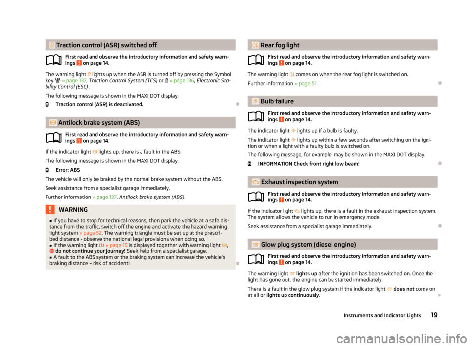
The warning light lights up when the ASR is turned off by pressing the Symbol
key
» page 137 , Traction Control System (TCS) or » page 136 , Electronic Sta-
bility Control (ESC) .
The following message is shown in the MAXI DOT display. Traction control (ASR) is deactivated.
Antilock brake system (ABS)
First read and observe the introductory information and safety warn-
ings
on page 14.
If the indicator light
lights up, there is a fault in the ABS.
The following message is shown in the MAXI DOT display. Error: ABS
The vehicle will only be braked by the normal brake system without the ABS.
Seek assistance from a specialist garage immediately.
Further information » page 137, Antilock brake system (ABS) .
WARNING■
If you have to stop for technical reasons, then park the vehicle at a safe dis-
tance from the traffic, switch off the engine and activate the hazard warning
light system » page 52. The warning triangle must be set up at the prescri-
bed distance - observe the national legal provisions when doing so.■
If the warning light » page 15 is displayed together with warning light ,
do not continue your journey! Seek help from a specialist garage.
■
A fault to the ABS system or the braking system can increase the vehicle's
braking distance – risk of accident!
Rear fog light
First read and observe the introductory information and safety warn-
ings
on page 14.
The warning light comes on when the rear fog light is switched on.
Further information » page 51.
Bulb failure
First read and observe the introductory information and safety warn-ings
on page 14.
The indicator light
lights up if a bulb is faulty.
The indicator light
lights up within a few seconds after switching on the igni-
tion or when a light with a faulty bulb is switched on.
The following message, for example, may be shown in the MAXI DOT display.
INFORMATION Check front right low beam!
Exhaust inspection system
First read and observe the introductory information and safety warn-
ings
on page 14.
If the indicator light
lights up, there is a fault in the exhaust inspection system.
The system allows the vehicle to run in emergency mode.
Seek assistance from a specialist garage immediately.
Glow plug system (diesel engine)
First read and observe the introductory information and safety warn-ings
on page 14.
The warning light
lights up after the ignition has been switched on. Once the
light has gone out, the engine can be started immediately.
There is a fault in the glow plug system if the indicator light
does not come on
at all or lights up continuously .
19Instruments and Indicator Lights
Page 25 of 266
Fog lightsFirst read and observe the introductory information and safety warn-
ings
on page 14.
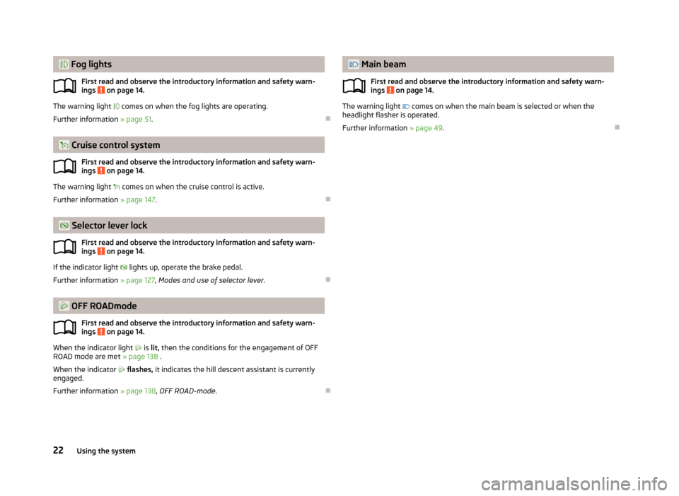
The warning light comes on when the fog lights are operating.
Further information » page 51.
Cruise control system
First read and observe the introductory information and safety warn-
ings
on page 14.
The warning light
comes on when the cruise control is active.
Further information » page 147.
Selector lever lock
First read and observe the introductory information and safety warn-
ings
on page 14.
If the indicator light
lights up, operate the brake pedal.
Further information » page 127, Modes and use of selector lever .
OFF ROADmode
First read and observe the introductory information and safety warn-ings
on page 14.
When the indicator light
is lit, then the conditions for the engagement of OFF
ROAD mode are met » page 138 .
When the indicator
flashes, it indicates the hill descent assistant is currently
engaged.
Further information » page 138, OFF ROAD-mode .
Main beam
First read and observe the introductory information and safety warn-ings
on page 14.
The warning light comes on when the main beam is selected or when the
headlight flasher is operated.
Further information » page 49.
22Using the system
Page 64 of 266
Seats and useful equipment
Front seats
Introduction
This chapter contains information on the following subjects:
Manually adjusting the front seats
62
Electric front seat adjustment
62
Memory Function of the electrically adjustable seat
63
Memory function of the remote control key
63
The driver's seat should be adjusted in such a way that the pedals can be fully
pressed to the floor with slightly bent legs.
The seat backrest on the driver's seat should be adjusted in such a way that the
upper point of the steering wheel can be easily reached with slightly bent arms.
Correct adjustment of the seats is particularly important for the following: › Reaching the controls safely and quickly.
› A relaxed and fatigue-free body position.
› Achieving the maximum protection offered by the seat belts and the airbag
system.
WARNINGGeneral information■Caution when adjusting the seat! You may suffer injuries or bruises as a re-
sult of adjusting the seat without paying proper attention.■
The electric front seat adjustment is also functional when the ignition is
turned off (even with the ignition key removed). Therefore children should
never be left unattended in the vehicle.
■
The seat backrests must not be tilted too far back when driving, as this will
impair the function of the seat belts and of the airbag system – risk of injury!
■
Never carry more people than there are number of seats in the vehicle.
■
Each occupant must correctly fasten the seat belt belonging to the seat.
Children must be fastened » page 177, Transporting children safely with a
suitable restraint system.
WARNING (Continued)■ The front seats and head restraints must be adjusted to match the body
size at all times and the seat belt must always be fastened properly to provide
the most effective levels of protection to the passengers.■
Do not carry any objects on the front passenger seat except objects de-
signed for this purpose (e.g. child seats) – risk of accident!
WARNINGInformation for the driver■Only adjust the driver's seat when the vehicle is stationary – risk of accident!■
Maintain a distance of at least 25 cm from the steering wheel, and a dis-
tance of at least 10 cm between the legs and the dash panel at the height of
the knee airbag. Not maintaining this minimum distance will mean that the
airbag system will not be able to properly protect you – hazard!
■
Ensure that there are no objects in the driver's footwell, as these may get
caught in the pedal apparatus when driving or braking » page 126. You would
then no longer be able to operate the clutch, brake or acceleration pedals.
WARNINGInformation for the front passenger■Maintain a distance of at least 25 cm to the dash panel. Not maintaining this
minimum distance will mean that the airbag system will not be able to proper-
ly protect you – hazard!■
Always keep your feet in the footwell when the car is being driven – never
place your feet on the instrument panel, out of the window or on the surfaces of the seats. You will be exposed to increased risk of injury if it becomes nec-
essary to apply the brake or in the event of an accident. If an airbag is de-
ployed, you may suffer fatal injuries when adopting an incorrect seated posi- tion!
Note
■ After a certain time, play can develop within the adjustment mechanism of the
backrest angle.■
For safety reasons, it is not possible to store the seat position in the electric
seat memory and remote control key memory if the inclination angle of the seat
backrest is more than 102° in relation to the seat cushion.
■
Each time you store the position of the electrically adjustable driver's seat and
exterior mirrors, the existing setting is deleted.
61Seats and useful equipment
Page 68 of 266
The seat heating can only be switched on when the engine is running.›
Press the surfaces of the controller in the area of the symbol or » Fig. 43 .
Pressing once switches the seat heating on at its maximum level - Level 3.
With repeated pressing of the switch, the intensity of the heating is down-regula-
ted up to the switch-off.
The intensity of the heating is indicated by the number of illuminated indicator
lights in the switch.WARNINGIf, as an occupant, you have a subdued pain and/or temperature sensitivity,
e.g. through medication, paralysis or because of chronic illness (e.g. diabetes),
we recommend not to use the seat heating. This can lead to burns on the
back, the posterior and the legs which are difficult to heal. If the seat heating
is used, we recommend to make regular breaks in your journey when driving
long distances, so that the body can recuperate from the stress of the jour-
ney. Please consult your doctor, who can evaluate your specific condition.
CAUTION
■ Do not kneel on the seats or otherwise apply concentrated pressure to them.■Do not turn on the seat heater if seats are not occupied.■
Do not switch on the seat heating if the seats have objects attached to or
placed on them, for example a child seat, a bag, etc. A fault of the heating ele-
ments in the seat heating can occur.
■
If additional seat covers or protective covers are attached to the seats, do not
turn on the seat heater - there is a risk of damaging the seat covers and seat
heating.
■
Do not clean the seats using moisture » page 194.
Note
If the on-board voltage drops, the seat heating is switched off automatically, in
order to provide sufficient electrical energy for the engine control » page 210,
Automatic load deactivation .
Front armrestFig. 44
Adjust armrest
First read and observe the introductory information given on page 64.
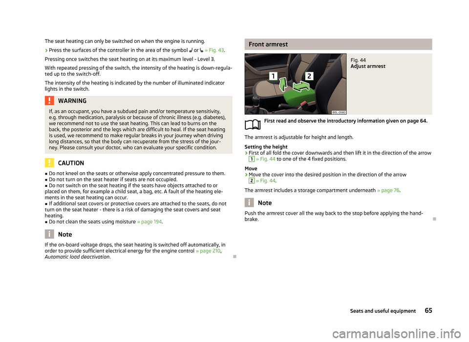
The armrest is adjustable for height and length.
Setting the height
›
First of all fold the cover downwards and then lift it in the direction of the arrow
1
» Fig. 44 to one of the 4 fixed positions.
Move
›
Move the cover into the desired position in the direction of the arrow
2
» Fig. 44 .
The armrest includes a storage compartment underneath » page 76.
Note
Push the armrest cover all the way back to the stop before applying the hand-
brake.
65Seats and useful equipment