fuel pressure SKODA YETI 2013 1.G / 5L Owner's Manual
[x] Cancel search | Manufacturer: SKODA, Model Year: 2013, Model line: YETI, Model: SKODA YETI 2013 1.G / 5LPages: 266, PDF Size: 26.71 MB
Page 17 of 266
The menu item Vehicle status is shown in the main menu of the MAXI DOT dis-
play whenever at least one fault message exists. After selecting this menu, the
first of the error messages is displayed. Several error messages are shown on the
display under the message e.g. 1/3. This indicates that the first of a total of three
error messages is being displayed.
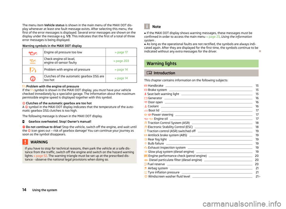
Warning symbols in the MAXI DOT displayEngine oil pressure too low» page 17Check engine oil level,
engine oil sensor faulty» page 203Problem with engine oil pressure» page 14Clutches of the automatic gearbox DSG are too hot» page 14
Problem with the engine oil pressure
If the
symbol is shown in the MAXI DOT display, you must have your vehicle
checked immediately by a specialist garage. The information about the maximum
permissible engine speed is displayed together with this symbol.
Clutches of the automatic gearbox are too hot
A
symbol in the MAXI DOT display indicates that the temperature of the auto-
matic gearbox DSG clutches is too high.
The following message is shown in the MAXI DOT display. Gearbox overheated. Stop! Owner's manual!
Do not continue to drive! Stop the vehicle, switch off the engine, and wait until
the
icon goes out – risk of gearbox damage! You can continue your journey as
soon as the symbol disappears.
WARNINGIf you have to stop for technical reasons, then park the vehicle at a safe dis- tance from the traffic, switch off the engine and switch on the hazard warning
lights » page 52 . The warning triangle must be set up at the prescribed dis-
tance - observe the national legal provisions when doing so.Note■ If the MAXI DOT display shows warning messages, these messages must be
confirmed in order to access the main menu » page 23, Using the information
system .■
As long as the operational faults are not rectified, the symbols are always indi-
cated again. After they are displayed for the first time, the symbols continue to be
indicated without any extra messages for the driver.
Warning lights
Introduction
This chapter contains information on the following subjects:
Handbrake
15
Brake system
15
Seat belt warning light
15
Generator
16
Door open
16
Coolant
16
Boot lid
17
Power steering
17
Engine oil
17
Traction Control System (ASR)
18
Electronic Stability Control (ESC)
18
Traction control (ASR) switched off
19
Antilock brake system (ABS)
19
Rear fog light
19
Bulb failure
19
Exhaust inspection system
19
Glow plug system (diesel engine)
19
Engine performance check (petrol engine)
20
Diesel particulate filter (diesel engine)
20
Fuel reserve
20
Airbag system
21
Tyre inflation pressure
21
Windscreen washer fluid level
21
14Using the system
Page 133 of 266
New brake padsFirst read and observe the introductory information given on page 129.
New brake pads do not initially provide optimal braking performance. They first
need to be “run in”. Therefore, drive especially carefully for the first 200 km or so.
Economical driving and environmental sustainability
Introduction
This chapter contains information on the following subjects:
Looking ahead
130
Economical gear changing
131
Avoiding full throttle
131
Reducing idling
131
Avoiding short distances
132
Checking tyre inflation pressure
132
Avoiding unnecessary ballast
132
Regular maintenance
132
Saving electrical energy
133
Environmental compatibility
133
The technical requirements for low fuel usage and economic efficiency of the ve-
hicle have already been built into the vehicle at the works. ŠKODA places a partic-
ular emphasis on minimising negative effects on the environment.
It is necessary to take note of the guidelines given in this chapter in order tomake best use of these characteristics and to maintain their effectiveness.
Fuel consumption, environmental pollution and the wear to the engine, brakes
and tyres depend essentially on the following three factors:
› your personal driving style
› operating conditions
› technical requirements
The fuel economy by can be improved by 10 -15 % by always looking ahead and
driving in an economical way.
Fuel consumption is also be influenced by external factors which are beyond the
driver's control. Consumption increases during the winter or under difficult condi-
tions, on poor roads, etc.
Fuel consumption can vary considerably from the manufacturer's data, as a result
of outside temperatures, the weather and driving style.
The optimal engine speed should be obtained when accelerating, in order to
avoid a high fuel consumption and resonance of the vehicle.
CAUTION
All the speed and engine revolution figures apply only when the engine is at its
normal operating temperature.
Looking ahead
First read and observe the introductory information and safety warn-
ings
on page 130.
A vehicle's highest fuel consumption occurs when accelerating, therefore unnec-
essary accelerating and braking should be avoided. If looking ahead when driving, less braking and consequently less accelerating are required.
If possible, let your vehicle coast to a stop, or use the engine brake, if you can see that the next set of traffic lights is on red, for example.
130Driving
Page 135 of 266
If an engine is only idling it takes much longer for it to reach its normal operating
temperature. Wear-and-tear and pollutant emissions, though, are particularly
high in the warming-up phase. Therefore, start driving as soon as the engine has
started, though high engine speeds should be avoided.
Avoiding short distances
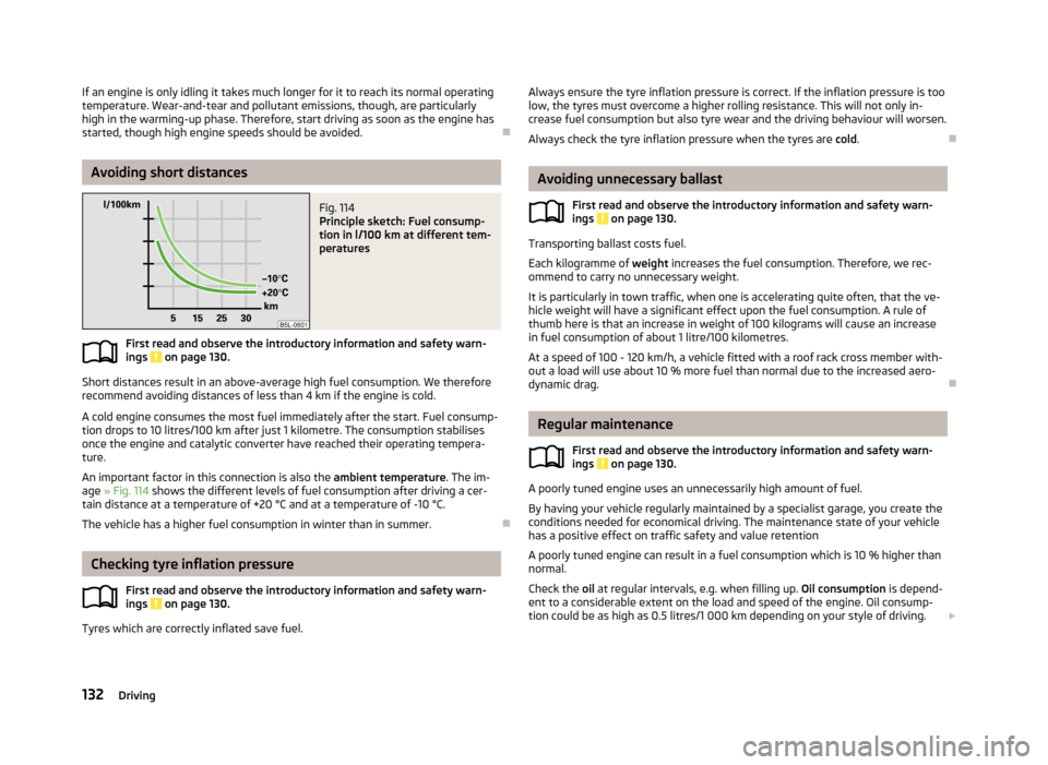
Fig. 114
Principle sketch: Fuel consump-
tion in l/100 km at different tem-
peratures
First read and observe the introductory information and safety warn- ings on page 130.
Short distances result in an above-average high fuel consumption. We therefore recommend avoiding distances of less than 4 km if the engine is cold.
A cold engine consumes the most fuel immediately after the start. Fuel consump-tion drops to 10 litres/100 km after just 1 kilometre. The consumption stabilises once the engine and catalytic converter have reached their operating tempera-
ture.
An important factor in this connection is also the ambient temperature. The im-
age » Fig. 114 shows the different levels of fuel consumption after driving a cer-
tain distance at a temperature of +20 °C and at a temperature of -10 °C.
The vehicle has a higher fuel consumption in winter than in summer.
Checking tyre inflation pressure
First read and observe the introductory information and safety warn-ings
on page 130.
Tyres which are correctly inflated save fuel.
Always ensure the tyre inflation pressure is correct. If the inflation pressure is too
low, the tyres must overcome a higher rolling resistance. This will not only in- crease fuel consumption but also tyre wear and the driving behaviour will worsen.
Always check the tyre inflation pressure when the tyres are cold.
Avoiding unnecessary ballast
First read and observe the introductory information and safety warn-
ings
on page 130.
Transporting ballast costs fuel.
Each kilogramme of weight increases the fuel consumption. Therefore, we rec-
ommend to carry no unnecessary weight.
It is particularly in town traffic, when one is accelerating quite often, that the ve-
hicle weight will have a significant effect upon the fuel consumption. A rule of
thumb here is that an increase in weight of 100 kilograms will cause an increase in fuel consumption of about 1 litre/100 kilometres.
At a speed of 100 - 120 km/h, a vehicle fitted with a roof rack cross member with-
out a load will use about 10 % more fuel than normal due to the increased aero- dynamic drag.
Regular maintenance
First read and observe the introductory information and safety warn-
ings
on page 130.
A poorly tuned engine uses an unnecessarily high amount of fuel.
By having your vehicle regularly maintained by a specialist garage, you create the conditions needed for economical driving. The maintenance state of your vehicle has a positive effect on traffic safety and value retention
A poorly tuned engine can result in a fuel consumption which is 10 % higher than normal.
Check the oil at regular intervals, e.g. when filling up. Oil consumption is depend-
ent to a considerable extent on the load and speed of the engine. Oil consump-
tion could be as high as 0.5 litres/1 000 km depending on your style of driving.
132Driving
Page 141 of 266
The HBA is activated by very quick operation of the brake pedal. In order to ach-
ieve the shortest possible braking distance, the brake pedal must be applied firm-
ly until the vehicle has come to a standstill.
The HBA function is automatically deactivated when the brake pedal is released.
The ABS is activated faster and more effectively with the intervention of the HBA.
Hill Hold Control (HHC)
First read and observe the introductory information and safety warn-ings
on page 136.
When driving on slopes, HHC allows you to move your foot from the brake pedalto the accelerator pedal without having to use the handbrake.
The system holds the brake pressure produced by the activation of the brakepedal for approx. 2 seconds after the brake pedal is released.
The brake pressure drops gradually the more you operate the accelerator pedal. If the vehicle does not start off within 2 seconds, it starts to roll back.
The HHC is active from a 5% slope if the driver's door is closed. HHC is only ever
active on slopes when in forward or reverse start off. When driving downhill, it is
inactive.
OFF ROAD-mode
Introduction
This chapter contains information on the following subjects:
Operation
138
Activation / deactivation
140
The OFF ROAD mode supports the driver when driving away from paved roads.
But even with OFF ROAD mode activated, your vehicle is never a true SUV.
WARNING■ A lack of fuel can cause irregular engine running or cause the engine to shut
down. This would lead the OFF ROAD mode to lose its effectiveness - risk of accident!■
Adjust the speed and driving style to the current visibility, weather, road and
traffic conditions.
■
The increased safety offered by the OFF ROAD mode must not tempt you to
take greater risks than otherwise - risk of an accident!
CAUTION
■ The OFF ROAD mode is not designed for the use on common roads.■All four wheels must be fitted with the same tyres approved by the manufactur-
er to ensure theOFF ROAD mode operates correctly.
Operation
First read and observe the introductory information and safety warn-
ings
on page 138.
The OFF ROAD mode is ready to intervene at speeds below 30 km / hr. The readi-
ness of the system is the warning light
displayed in the instrument cluster.
The following functions are integrated in the OFF ROAD mode.
› Downhill Drive Support.
› Start-Off Assist.
› ABS OFF ROAD.
› TCS OFF ROAD.
› EDL OFF ROAD.
Downhill Drive Support
The hill descent assistant, with its automatic braking action on all wheels, en-
sures a constant speed on a steep slope when driving forwards and reversing.
The speed maintained corresponds to the speed of the vehicle at the time the As- sistant was first engaged.
During an intervention of the Assistants, the warning light
flashes in the in-
strument cluster.
By pressing the accelerator or brake pedal, the speed can be increased or re- duced. This is true even if the shift lever is in the neutral position and the selector
lever in the N position.
138Driving
Page 216 of 266
WARNINGInformation on the wheel bolts■The wheel bolts must be clean and must turn easily. Never treat them with
grease or oil.■
The prescribed tightening torque of the wheel bolts for steel and light alloy
wheels is 120 Nm.
■
If the wheel bolts are tightened to a too low tightening torque, the rim can
come loose when the car is moving – risk of accident! A tightening torque
which is too high can damage the bolts and threads and this can result in per-
manent deformation of the contact surfaces on the rim.
■
In case of incorrect treatment of the wheel bolts, the wheel can loosen
when the car is moving – risk of accident!
WARNINGInformation on the spare wheel■Only use the spare wheel while absolutely necessary.■
Never drive with more than one spare wheel mounted.
■
The snow chains cannot be used on the spare wheel.
CAUTION
■ If a spare wheel is used that is not identical to the fitted tyres, the following
must be observed » page 216, Spare wheel .■
Protect the tyres from contact with oil, grease and fuel.
■
Replace lost valve caps.
■
If, in the event of a puncture, it is necessary to fit a spare wheel with a tyre
without a dedicated running direction or with the opposite direction of rotation, drive carefully as the optimal characteristics of the tyre are no longer applicable in
this situation.
For the sake of the environment
Tyres that are insufficiently inflated increase your fuel consumption.
Note
■ We recommend that any work on the wheels or tyres be carried out by a spe-
cialist garage.■
We recommend that you use wheel rims, tyres, full wheel trims and snow chains
from ŠKODA Original Accessories.
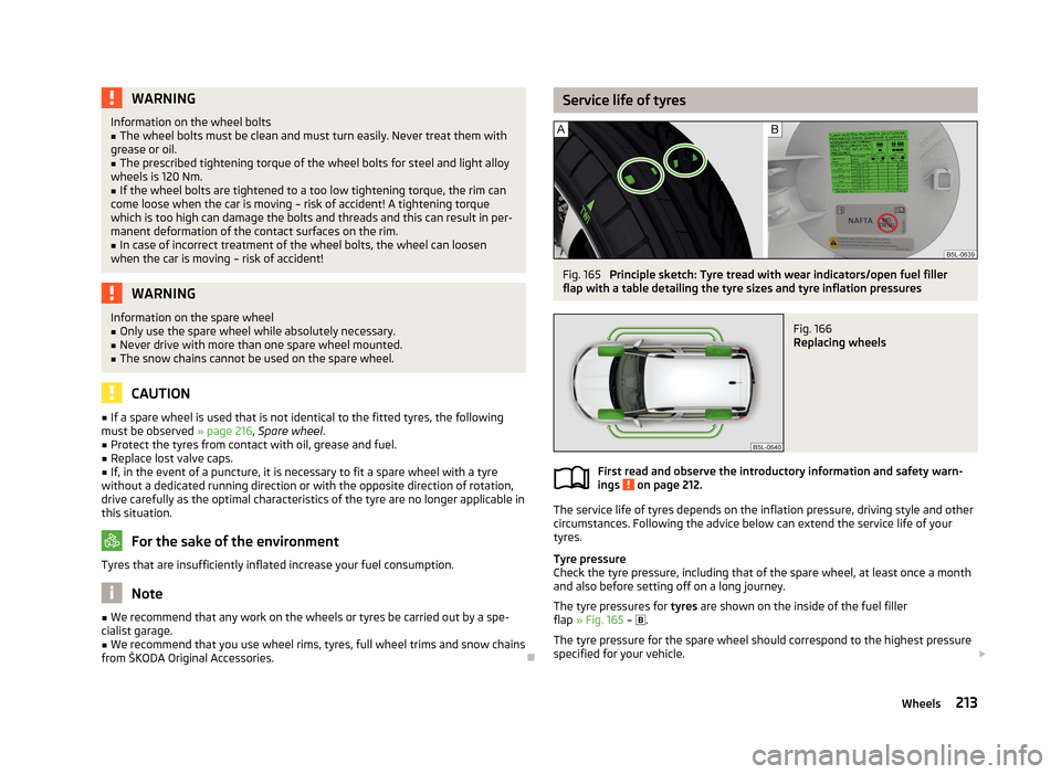
Service life of tyresFig. 165
Principle sketch: Tyre tread with wear indicators/open fuel filler
flap with a table detailing the tyre sizes and tyre inflation pressures
Fig. 166
Replacing wheels
First read and observe the introductory information and safety warn-
ings on page 212.
The service life of tyres depends on the inflation pressure, driving style and other
circumstances. Following the advice below can extend the service life of your
tyres.
Tyre pressure
Check the tyre pressure, including that of the spare wheel, at least once a month and also before setting off on a long journey.
The tyre pressures for tyres are shown on the inside of the fuel filler
flap » Fig. 165 –
.
The tyre pressure for the spare wheel should correspond to the highest pressure
specified for your vehicle.
213Wheels
Page 229 of 266
Sealing and inflating the tyreFirst read and observe the introductory information and safety warn-
ings
on page 224.
Sealing
›
Forcefully shake the tyre inflator bottle
10
» Fig. 178 on page 225 several times.
›
Firmly screw the inflation hose
3
onto the tyre inflator bottle
10
in a clockwise
direction. The film on the cap is pierced automatically.
›
Remove the plug from the inflation hose
3
and plug the open end fully onto
the tyre valve.
›
Hold the bottle
10
with the bottom facing upwards and fill all of the sealing
agent from the tyre inflator bottle into the tyre.
›
Remove the empty tyre inflator bottle from the valve.
›
Screw the valve core back into the tyre valve using the valve remover
2
.
Inflating
›
Screw the air compressor tyre inflation hose
7
» Fig. 178 on page 225 firmly on-
to the tyre valve.
›
Start the engine and run it in idle.
›
Plug the connector
6
into 12 Volt socket » page 75.
›
Switch on the air compressor with the ON and OFF switch
9
.
›
Allow the air compressor to run until a pressure of 2.0 - 2.5 bar is achieved. Max-
imum run time of 8 minutes » !
›
Switch off the air compressor.
›
If you cannot reach an air pressure of 2.0 – 2.5 bar, unscrew the tyre inflation
hose
7
from the tyre valve.
›
Drive the vehicle 10 metres forwards or backwards to allow the sealing agent to
“distribute” in the tyre.
›
Firmly screw the tyre inflation hose
7
back onto the tyre valve and repeat the
inflation process.
›
If you cannot reach the required tyre inflation pressure here either, this means
the tyre has sustained too much damage. You cannot seal with tyre with the breakdown kit »
.
›
Switch off the air compressor.
›
Remove the tyre inflation hose
7
from the tyre valve.
Once a tyre inflation pressure of 2.0 – 2.5 bar is achieved, continue the journey at
a maximum speed of 80 km/h (50 mph).
Check the tyre inflation pressure after driving for 10 minutes » page 226, Check
after 10 minutes' driving .
WARNING■
During inflation, the tyre inflation hose and air compressor may get hot –
risk of injury!■
Do not place the hot tyre inflation hose or hot air compressor on flammable
materials – risk of fire!
■
If you cannot inflate the tyre to at least 2.0 bar, this means the damage sus-
tained was too serious. The sealing agent cannot be used to seal the tyre.
Do not drive the vehicle! Seek help from a specialist garage.
CAUTION
Switch off the air compressor after running 8 minutes at the latest – risk of over-
heating! Allow the air compressor to cool a few minutes before switching it on
again.
Check after 10 minutes' driving
First read and observe the introductory information and safety warn-ings
on page 224.
Check the tyre inflation pressure after driving for 10 minutes!
If the tyre inflation pressure is 1.3 bar or less
›
Do not drive the vehicle! You cannot properly seal with tyre with the break-
down kit.
If the tyre inflation pressure is 1.3 bar or more
›
Adjust the tyre inflation pressure to the correct value (see inside of fuel filler cap).
›
Continue driving carefully to the nearest specialist garage at a maximum speed
of 80 km/h (50 mph).
Jump-starting
Introduction
This chapter contains information on the following subjects:
Jump-starting using the battery from another vehicle
227
Jump-starting in vehicles with the START-STOP system
228
226Do-it-yourself
Page 240 of 266
›Insert a new fuse.›Replace the bracket at the original position.›
Re-insert the cover of the fuse box .
Fuse assignment in the dash panel
No.Power consumer1Heating of the gearbox ventilation (diesel engine)
Control unit for automatic gearbox DSG2-3Tow hitch4Instrument cluster, windshield wiper lever, turn signal light lever,
camera5Air blower for heating, radiator fan, air conditioning system, Clima-
tronic6Rear window wiper7Phone8Tow hitch9Vehicle voltage control unit - interior lights
Rear fog light10Rain sensor, light switch, diagnosis connector, removable light11Left side cornering lights12Right side cornering lights13Radio, DVD14Central control unit, engine control unit15Light switch16Haldex17KESSY controller, steering wheel locking18Diagnostic socket, engine control unit, brake sensor, Haldex19Control unit for ABS, ESP, switch for tyre air pressure control, control
unit for parking aid, switch for OFF ROAD mode, START STOP button20Switch and airbag control unit21WIV, tail lamp, dimming mirror, pressure sensor, telephone prepara- tion, air mass sensor, control unit for headlight range control and
headlight tilt22Instrument cluster controller for electro-mechanical power steering, control unit for data bus23Central locking system and bonnet lidNo.Power consumer24Rear power window25Rear window heater, auxiliary heating and ventilation26Power socket in the boot27Electric sliding/tilting roof, electric sun screen28Fuel pump, injection valves29Front power window30front and rear lighter31Headlight cleaning system32Front seat heating, regulator for seat heating33Heating, air conditioning, Climatronic, remote control for auxiliary
heating34Alarm, spare horn35Control unit for automatic gearbox DSG36Tow hitch
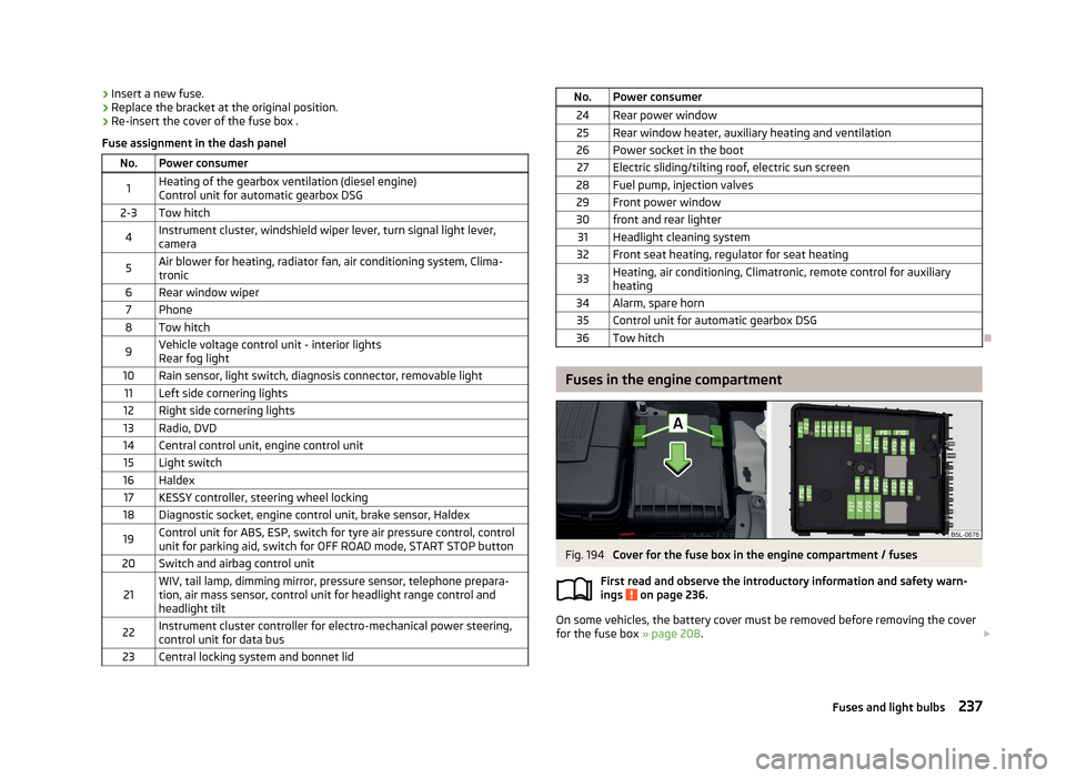
Fuses in the engine compartment
Fig. 194
Cover for the fuse box in the engine compartment / fuses
First read and observe the introductory information and safety warn-
ings
on page 236.
On some vehicles, the battery cover must be removed before removing the cover
for the fuse box » page 208.
237Fuses and light bulbs
Page 241 of 266
Replacing fuses›Move the safety catch of the cover of the fuse box A » Fig. 194 in the direction
of the arrow.
The symbol is displayed behind the catches.›
Remove the cover.
›
Replace the appropriate fuse.
›
Replace the cover on the fuse box and the safety clip
A
move against the ar-
row.
The symbol is displayed behind the catches.
The cover is locked into position.
CAUTION
The cover for the fuse box in the engine compartment must always be applied
correctly. Water may get into the fuse box if the cover is not replaced properly -
there is a risk of damage to the vehicle!
Assignment of fuses in the engine compartment
First read and observe the introductory information and safety warn-ings
on page 236.
Fuse assignment in engine compartment
No.Power consumer1Not assigned2Control unit for automatic gearbox3Measuring circuit4ABS control unit5Control unit for automatic gearbox6Not assigned7Power supply terminal 15, Starter8Radio, instrument cluster, telephone9Not assigned10Engine control unit11Auxiliary heating and ventilation control unit12Data bus control unitNo.Power consumer13Engine control unit14Ignition15Lambda probe, fuel pump relay
Glow plug system16Vehicle voltage control unit, right headlight, right tail light17Horn18Amplifier for digital sound processor19Windscreen wipers20Control valve for fuel pressure, high pressure pump21Lambda probe22Clutch pedal switch, brake pedal switch23Coolant pump
Charge pressure control solenoid valve, changeover valve for radiator
Fuel high pressure pump24Active charcoal filter, exhaust gas recirculation valve, radiator fan25ABS control unit26Vehicle voltage control unit, left headlight, left tail light27Glow Plug System28Windscreen heater29Power supply of the interior30Terminal X a)a)
In order not to drain the battery unnecessarily when starting the engine, the electrical components
of this terminal are automatically switched off.
Bulbs
Introduction
This chapter contains information on the following subjects:
Bulb arrangement in the headlights
239
Change halogen bulb
240
Remove the protective grille for fog lights
240
238Do-it-yourself
Page 256 of 266
Counter for distance driven13
Cruise control system Activating/deactivating
148
Changing the stored speed148
Storing and maintaining speed148
Switching off temporarily148
Warning light22
Cruise Control System147
Cupholders73
D
DAY LIGHT see Daylight running lights
48
Daylight running lights48
De-icing the windscreen and rear window55
Deactivating an airbag175
Decorative films190
Delayed locking of the boot lid see Boot lid
41
Diesel refer to Fuel
198
diesel - particulate filter
20
Diesel fuel Operation in winter
198
Diesel particulate filter warning light
20
Digital Clock Time
13
Dipstick203
Disconnecting and reconnecting vehicle battery
210
Display12
Compass points25
Coolant temperature11
Correct gear changes24
Fuel supply12
Service intervals30
Display of the second speed13
Distance driven13
Door Child safety lock
37
Closing37
Emergency locking233
Emergency locking the driver's door232
Opening37
warning light door open16
Door open warning light
16
Driver Steering Recommendation (DSR)137
Driving Abroad
135
Emissions244
Fording water on roads134
Fuel consumption244
Maximum speed247
on unpaved roads135
driving away from paved roads135
Driving economically Economical gear changing
131
Driving with a trailer157
DSR137
DVD-preinstallation116
E
Economical driving
130
Ballast132
Driving at full throttle131
Idling131
Looking ahead130
Regular maintenance132
Saving energy133
Short distances132
Tyre inflation pressure132
EDL Operation
137
Electrical power windows43
Button in the driver's door41, 42
Button in the rear doors43
Operational faults44
Electronic Differential Lock (EDL)137
Electronic immobiliser119
Electronic Stability Control (ESC)136
emergency replace battery in the remote control
231
Emergency Activation of the sliding/tilting roof
234
Changing a wheel221
Hazard warning light system52
Jump-starting226, 227
Locking the door without a locking cylinder233
Locking the driver's door232
Selector lever-unlocking233
Sliding/tilting roof234
Start engine - KESSY123
Switching off the ignition –KESSY123
Towing the using the tow hitch230
Towing the vehicle228
Tyre repair224
Unlocking the driver's door232
Unlocking the tailgate233
emergency equipment reflective vest
219
Emergency equipment First aid kit
219
Jack220
Vehicle tool kit220
Warning triangle219
Emissions244
Engine Running in
129
Engine compartment199
Brake fluid206
Coolant205
Overview201
Vehicle battery207
engine oil information messages
17
warning light17
253Index
Page 259 of 266
Luggage compartment lid40
M
Main beam
49
Warning light22
Maintenance132
Decorative films190
Manual air conditioning Operating elements
94
Manual gear changing see gear changing
125
Materials defect liability5
MAXI DOT See MAXI DOT display
28
MAXI DOT display28
Main menu28
Operation23
Settings29
Maximum speed247
Memory Function for the seat63
MFD See multifunction display
25
Mirror Exterior mirrors
59
Mirrors Interior mirror
59
Vanity55
Mobile phone100, 103, 105
Connecting to the hands-free system103, 106
Modes of the automatic transmission127
Modifications184
Modifications and technical alterations Airbags
186
Service185
Spoiler186
Multifunction display Functions
25
Information26
Memory26
Operation23
Multimedia113
AUX115
MDI115
N
N1
88
Net partition86
Nets83
O
OFF ROAD
138
activation / deactivation140
operation138
OFF ROAD mode warning light
22
oil information messages
17
Oil See Engine oil
203
oil pressure information messages
17
On-board computer See multifunction display
25
Operate windscreen wipers
57
Operation in winter Diesel fuel
198
Vehicle battery209
Outside temperature26
Overhang angle246
Overview Engine compartment
201
Warning lights14
P
Paintwork See Paintwork care
189
Paintwork care189
Park assist143
Finding a parking space144
Information messages146
Parking145
Parking Automatic brake assist
146
Manoeuvring out of a parallel parking space146
Park assist143
Parking aid140
Parking aid140
Function141
Parking vehicle38
Part replacement184
Passive safety Before setting off
160
Driving safety161
Safety equipment160
Passive Safety160
Pedals126
Footmats126
Petrol refer to Fuel
197
pitch angle246
Polishing the paintwork See Taking care of your vehicle
189
Power outlet 12 V
75
Power steering118
Warning light17
Power windows Button in the front passenger door
43
Practical equipment Reflective vest
219
256Index