turn signal SKODA YETI 2015 1.G / 5L Owner's Guide
[x] Cancel search | Manufacturer: SKODA, Model Year: 2015, Model line: YETI, Model: SKODA YETI 2015 1.G / 5LPages: 232, PDF Size: 30.84 MB
Page 118 of 232
Under certain circumstances (e.g. after switching off the ignition and opening
the driver's door), the steering is enabled only when the ignition is switched on
or the engine is started.WARNINGNever let the vehicle roll with locked steering lock - there is a risk of acci-
dent!
Switch ignition on / off
Read and observe
and on page 115 first.
›
Press the button » Fig. 130 on page 115 briefly.
The ignition is switched on or off.
On vehicles fitted with a manual gearbox, the clutch pedal must not be de-
pressed while switching the ignition on or off, otherwise the system would try
to start.
On vehicles fitted with a automatic gearbox, the brake pedal must not be de-
pressed while switching the ignition on or off, otherwise the system would try
to start.
If the driver's door is opened while the ignition is on, an audible signal sounds
and the following message appears in the instrument cluster display.
Ignition on.IGNITION ON
When leaving the vehicle always switch off the ignition.
Starting the engine
Read and observe
and on page 115 first.
Starting the engine
›
Firmly apply the handbrake.
›
For vehicles with manual transmission , shift gear stick to neutral, depress
the clutch pedal and hold it there until the engine starts.
›
On vehicles with automatic transmission , place the selector lever in position
P or N and depress the brake pedal until the engine starts.
› Press and hold the starter button
» Fig. 130 on page 115 1)
until the engine
starts.
In vehicles with diesel engines after pressing the button, the glow plug warn-
ing light
lights up. The engine can be started after the indicator light goes
out.
Note
■ The engine running noises may louder at first be louder for a short time after
starting the cold engine. This is quite normal and is not an operating problem.■
You should not switch on any major electrical components during the heat-
ing period otherwise the vehicle battery will be drained unnecessarily.
Switching off the engine
Read and observe
and on page 115 first.
Switching off
›
Stop the vehicle » page 121, Parking .
›
Press the button » Fig. 130 on page 115 briefly.
The engine and the ignition are switched off simultaneously.
Emergency shutdown
If necessary and in exceptional cases, the engine may even be turned off while
driving.
›
Press the starter button » Fig. 130 on page 115 for longer than 1 second or
twice within 1 second.
After the emergency stop of the motor, the steering lock will remain unlocked.
CAUTION
Do not switch the engine off immediately at the end of your journey after the
engine has been operated over a prolonged period at high loads but leave it to
run at an idling speed for about 1 minute. This prevents any possible accumula-
tion of heat when the engine is switched off.
Note
After switching off the ignition, the radiator fan may intermittently continue to
operate for approx. 10 minutes.1)
On vehicles with the START-STOP system, it is sufficient to press the starter button briefly. The motor
will then automatically start.
116Driving
Page 119 of 232
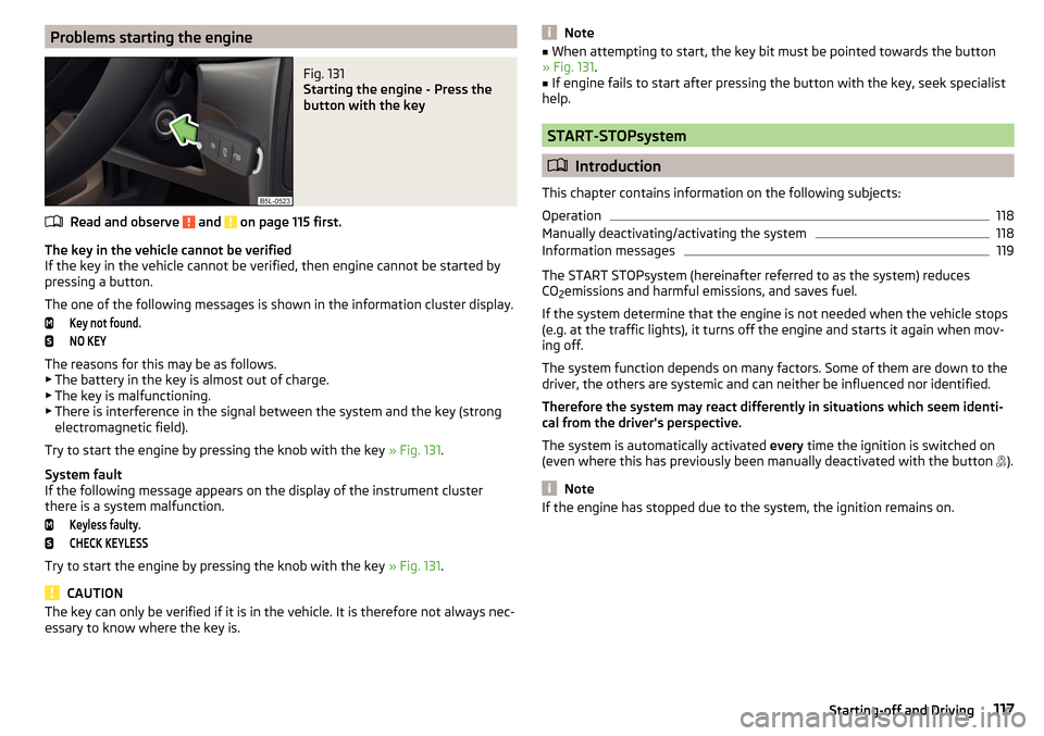
Problems starting the engineFig. 131
Starting the engine - Press the
button with the key
Read and observe and on page 115 first.
The key in the vehicle cannot be verified
If the key in the vehicle cannot be verified, then engine cannot be started by pressing a button.
The one of the following messages is shown in the information cluster display.
Key not found.NO KEY
The reasons for this may be as follows.
▶ The battery in the key is almost out of charge.
▶ The key is malfunctioning.
▶ There is interference in the signal between the system and the key (strong
electromagnetic field).
Try to start the engine by pressing the knob with the key » Fig. 131.
System fault
If the following message appears on the display of the instrument cluster
there is a system malfunction.
Keyless faulty.CHECK KEYLESS
Try to start the engine by pressing the knob with the key » Fig. 131.
CAUTION
The key can only be verified if it is in the vehicle. It is therefore not always nec-
essary to know where the key is.Note■ When attempting to start, the key bit must be pointed towards the button
» Fig. 131 .■
If engine fails to start after pressing the button with the key, seek specialist
help.
START-STOPsystem
Introduction
This chapter contains information on the following subjects:
Operation
118
Manually deactivating/activating the system
118
Information messages
119
The START STOPsystem (hereinafter referred to as the system) reduces
CO 2emissions and harmful emissions, and saves fuel.
If the system determine that the engine is not needed when the vehicle stops
(e.g. at the traffic lights), it turns off the engine and starts it again when mov-
ing off.
The system function depends on many factors. Some of them are down to the
driver, the others are systemic and can neither be influenced nor identified.
Therefore the system may react differently in situations which seem identi-
cal from the driver's perspective.
The system is automatically activated every time the ignition is switched on
(even where this has previously been manually deactivated with the button ).
Note
If the engine has stopped due to the system, the ignition remains on.117Starting-off and Driving
Page 136 of 232
OperationFig. 147
Position of the camera / monitored area
Read and observe
and on page 133 first.
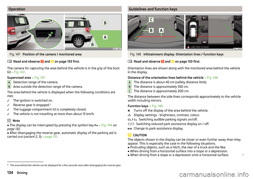
The camera for capturing the area behind the vehicle is in the grip of the boot
lid » Fig. 147 .
Supervised area » Fig. 147
Detection range of the camera.
Area outside the detection range of the camera.
The area behind the vehicle is displayed when the following conditions are
met.
The ignition is switched on.
Reverse gear is engaged. 1)
The luggage compartment lid is completely closed.
The vehicle is not travelling at more than about 15 km/h.
Note
■ The display can be interrupted by pressing the symbol key » Fig. 144 on
page 132 .■
After disengaging the reverse gear, automatic display of the parking aid is
carried out (variant 2, 3) » page 131.
ABGuidelines and function keysFig. 148
Infotainment display: Orientation lines / function keys
Read and observe
and on page 133 first.
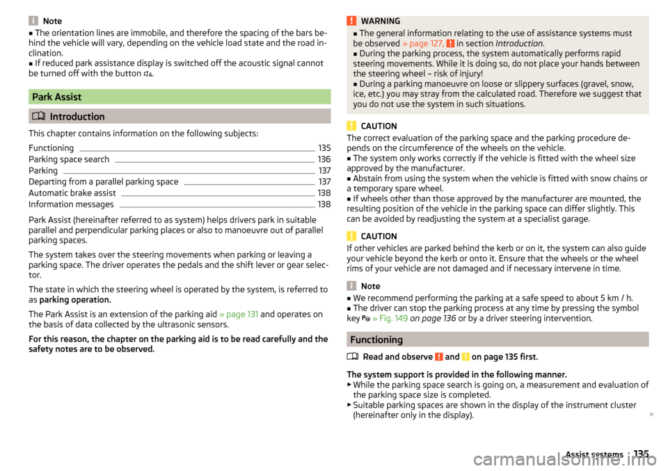
Orientation lines are shown along with the monitored area behind the vehicle
in the display.
Distance of the orientation lines behind the vehicle » Fig. 148
The distance is about 40 cm (safety distance limit).
The distance is approximately 100 cm.
The distance is approximately 200 cm.
The distance between the side lines corresponds approximately to the vehicle width including mirrors.
Function keys » Fig. 148
Turns off the display of the area behind the vehicle.
Display settings - brightness, contrast, colour. Switching audible parking signals on/off.
Switching reduced park assistance display on / off.
Change to park assistance display.
CAUTION
The objects shown in the display can be closer or even further away than they
appear. This is especially the case in the following situations.■
Protruding objects, such as a hitch, the rear of a truck and the like.
■
When driving from a horizontal surface into a slope or a depression.
■
When driving from a slope or a depression onto a horizontal surface.
ABC
1)
The area behind the vehicle can be displayed for a few seconds more after disengaging the reverse gear.
134Driving
Page 137 of 232
Note■The orientation lines are immobile, and therefore the spacing of the bars be-
hind the vehicle will vary, depending on the vehicle load state and the road in-
clination.■
If reduced park assistance display is switched off the acoustic signal cannot
be turned off with the button
.
Park Assist
Introduction
This chapter contains information on the following subjects:
Functioning
135
Parking space search
136
Parking
137
Departing from a parallel parking space
137
Automatic brake assist
138
Information messages
138
Park Assist (hereinafter referred to as system) helps drivers park in suitable
parallel and perpendicular parking places or also to manoeuvre out of parallel
parking spaces.
The system takes over the steering movements when parking or leaving a
parking space. The driver operates the pedals and the shift lever or gear selec-
tor.
The state in which the steering wheel is operated by the system, is referred to
as parking operation.
The Park Assist is an extension of the parking aid » page 131 and operates on
the basis of data collected by the ultrasonic sensors.
For this reason, the chapter on the parking aid is to be read carefully and the safety notes are to be observed.
WARNING■ The general information relating to the use of assistance systems must
be observed » page 127, in section Introduction .■
During the parking process, the system automatically performs rapid
steering movements. While it is doing so, do not place your hands between
the steering wheel – risk of injury!
■
During a parking manoeuvre on loose or slippery surfaces (gravel, snow,
ice, etc.) you may stray from the calculated road. Therefore we suggest that
you do not use the system in such situations.
CAUTION
The correct evaluation of the parking space and the parking procedure de-
pends on the circumference of the wheels on the vehicle.■
The system only works correctly if the vehicle is fitted with the wheel size
approved by the manufacturer.
■
Abstain from using the system when the vehicle is fitted with snow chains or
a temporary spare wheel.
■
If wheels other than those approved by the manufacturer are mounted, the
resulting position of the vehicle in the parking space can differ slightly. This
can be avoided by readjusting the system at a specialist garage.
CAUTION
If other vehicles are parked behind the kerb or on it, the system can also guide
your vehicle beyond the kerb or onto it. Ensure that the wheels or the wheel
rims of your vehicle are not damaged and if necessary intervene in time.
Note
■ We recommend performing the parking at a safe speed to about 5 km / h.■The driver can stop the parking process at any time by pressing the symbol
key
» Fig. 149 on page 136 or by a driver steering intervention.
Functioning
Read and observe
and on page 135 first.
The system support is provided in the following manner.▶ While the parking space search is going on, a measurement and evaluation of
the parking space size is completed.
▶ Suitable parking spaces are shown in the display of the instrument cluster
(hereinafter only in the display).
135Assist systems
Page 138 of 232
▶The display shows instructions and information before the start and during
the parking.
▶ The road way is calculated that the vehicle uses during the parking.
▶ The front wheels are automatically rotated during the parking.
Conditions for the system function
The system can look for a parking space only if the following basic conditions
are met.
The system is activated.
The vehicle speed is less than 40 km / h (parallel parking).
The vehicle speed is less than 20 km / h (transverse parking).
The distance to a number of parked vehicles is approximately 0.5 - 1.5 m.
The TCS is activated » page 127, Braking and stabilisation systems .
The system can only carry out the parking if the following basic conditions are
met.
The vehicle is travelling less than about 7 km/h.
The parking procedure takes less than 6 minutes.
There is no driver intervention in the automatic steering operation.
Activation/deactivation
The system can be enabled or disabled by pressing the symbol key
» Fig. 149
on page 136 -
.
When the system is activated, the symbol illuminates.
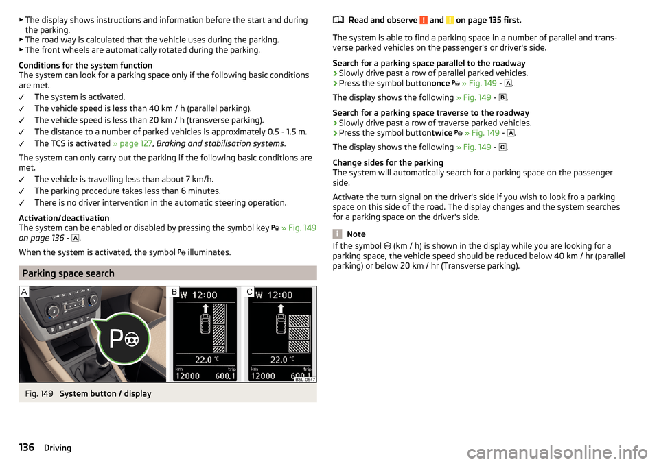
Parking space search
Fig. 149
System button / display
Read and observe and on page 135 first.
The system is able to find a parking space in a number of parallel and trans-
verse parked vehicles on the passenger's or driver's side.
Search for a parking space parallel to the roadway
›
Slowly drive past a row of parallel parked vehicles.
›
Press the symbol button once
» Fig. 149 -
.
The display shows the following » Fig. 149 -
.
Search for a parking space traverse to the roadway
›
Slowly drive past a row of traverse parked vehicles.
›
Press the symbol button twice
» Fig. 149 -
.
The display shows the following » Fig. 149 -
.
Change sides for the parking
The system will automatically search for a parking space on the passenger
side.
Activate the turn signal on the driver's side if you wish to look fro a parking
space on this side of the road. The display changes and the system searches
for a parking space on the driver's side.
Note
If the symbol (km / h) is shown in the display while you are looking for a
parking space, the vehicle speed should be reduced below 40 km / hr (parallel parking) or below 20 km / hr (Transverse parking).136Driving
Page 139 of 232
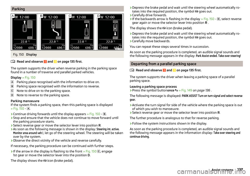
ParkingFig. 150
Display
Read and observe
and on page 135 first.
The system supports the driver when reverse parking in the parking space
found in a number of traverse and parallel parked vehicles.
Display » Fig. 150
Parking place recognised with the information to drive on.
Parking space recognised with the information to reverse.
Note to drive on to the parking space.
Note to reverse to the parking space.
Parking manoeuvre
If the system finds a parking space, then this parking space is displayed
» Fig. 150 -
.
›
Continue driving forwards until the display appears
» Fig. 150 -
.
›
Stop and ensure that the vehicle does not continue to move forward until
the parking procedure starts.
›
Select reverse gear or move the selector lever into position R.
›
As soon as the following message is shown in the display:
Steering int. active.Monitor area around veh.!
, let go of the steering wheel. The steering will be taken
over by the system.
›
Observe the direct vicinity of the vehicle and reverse carefully.
If necessary, the parking procedure can be continued with further steps.
›
If the arrow in the display is flashing to the front » Fig. 150
, engage
1st gear or move the selector lever into the position D.
The display shows the icon (brake pedal).
›Depress the brake pedal and wait until the steering wheel automatically ro-
tates into the required position, the symbol goes out.›
Carefully drive forwards.
›
If the backwards arrow is flashing in the display » Fig. 150 -
, select reverse
gear again or move the selector lever into position R .
The display shows the
icon (brake pedal).
›
Depress the brake pedal and wait until the steering wheel automatically ro-
tates into the required position, the symbol
goes out.
›
Carefully move backwards.
You can repeat these steps several times in succession.
As soon as the parking procedure is completed, an audible signal sounds and
the following message appears in the display:
Park Assist ended. Take over steering!
Departing from a parallel parking space
Read and observe
and on page 135 first.
The system supports the driver when leaving a parking space of a parallel
parking space.
Leaving a parking space process
›
Press the symbol button once
» Fig. 149 on page 136 .
The following message is displayed:
PARK ASSIST Turn on turn signal and select reversegear.›
Activate the turn signal for side of the vehicle where the parking space is out
of which you wish to manoeuvre.
›
Select reverse gear or move the selector lever into position R.
The further procedure is analogous to that for reverse parking.
›
Follow the system instructions shown in the display.
As soon as the parking procedure is completed, an audible signal sounds and
the following message appears in the information display:
Take over steering andcontinue driving.137Assist systems
Page 192 of 232
›Attach the clamp 4 to a solid metal part which is connected firmly to the en-
gine block or to the engine block itself.
The jump-start cable must be connected to the engine earthing point only on
vehicles with the START-STOP system » Fig. 188.
Starting engine›
Start the engine on the vehicle providing the power and allow it to idle.
›
Start the engine of the vehicle with the discharged battery.
›
If the engine does not start, terminate the attempt to start the engine after
10 seconds and wait for 30 seconds before repeating the process.
›
Remove the jump start cables in the reverse order as attachment.
Both batteries must have a rated voltage of 12 V. The capacity (Ah) of the bat-
tery supplying the power must not be significantly less than the capacity of
the discharged battery in your vehicle.
Jump-start cables
Only use jump-start cables which have an adequately large cross-section and
insulated terminal clamps. Observe the instructions of the jumper lead manu-
facturer.
Positive cable - colour coding in the majority of cases is red.
Negative cable - colour coding in the majority of cases is black.
WARNING■
Do not clamp the jump-start cable to the negative terminal of the dis-
charged battery. There is the risk of detonating gas seeping out the battery being ignited by the strong spark which results from the engine being star-
ted.■
The non-insulated parts of the terminal clamps must never touch each
other – risk of short circuit!
■
The jump-start cable connected to the positive terminal of the battery
must not come into contact with electrically conducting parts of the vehicle
– risk of short circuit!
■
Route the jump-start cables so that they cannot be caught by any rotat-
ing parts in the engine compartment.
Towing the vehicle
Introduction
Fig. 189
Braided tow rope / Spiral tow rope
This chapter contains information on the following subjects:
Front towing eye
191
Rear towing eye
192
Vehicles with a tow hitch
192
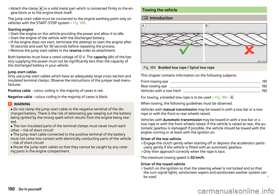
For towing, a braided tow rope is to be used » Fig. 189 -
.
When towing, the following guidelines must be observed.
Vehicles with manual transmission may be towed in with a tow bar or a tow
rope or with the front or rear wheels raised.
Vehicles with Automatic transmission may be towed in with a tow bar or a
tow rope or with the front wheels raised. If the vehicle is raised at rear, the au-
tomatic gearbox is damaged! If possible, the vehicle should be towed with the
engine running or at least with the ignition on.
Driver of the tow vehicle
›
Engage the clutch gently when starting off or depress the accelerator partic-
ularly gently if the vehicle is fitted with an automatic gearbox.
›
Only then approach correctly when the rope is taut.
The maximum towing speed is 50 km/h.
Driver of the towed vehicle
›
Switch on the ignition so that the steering wheel is not locked and so that
the turn-signal lights, windscreen wipers and windscreen washer system can
be used.
190Do-it-yourself
Page 217 of 232
Cleaning the vehicle exteriorCamera lens156
Cavity protection156
Decorative films154
Door locking cylinder156
Headlight glasses155
Protective films154
Towing hitch157
Under-body protection157
wheels156
Cleaning vehicle152
Cleaning vehicle exterior153
Anodized parts155
Chrome parts155
Plastic parts155
Rubber seals155
Vehicle paint work154
Wiper blades157
Clean interior Safety belt
159
Climatronic air distribution control
107
Automatic operation107
Operating elements106
Clothes hook92
Cockpit 12-Volt power outlet
88
Ashtray87
Cigarette lighter86
General view27
Lighting69
storage compartments83
useful equipment83
Comfort control window
61
COMING HOME67
compartments83
Component protection151
Components of the puncture repair kits187
Computer See multifunction display41
Convenience operation sliding / tilting roof
62
convenience turn signal66
Coolant169
Checking170
Messages33
Replenishing171
Temperature gauge29
Warning light33
CORNER see Headlights with CORNER function
67
Cornering lights Display messages
36
Correct routing of seat belt
12
Correct seated position8
Front passenger10
Rear seats10
Correct seat position Driver
9
Counter for distance driven30
cruise control operation
139
operation description139
Cruise control system Warning light
39
Cup holders85
D
DAY LIGHT see Daylight running lights
65
Daylight running lights65
De-icing windows
155
De-icing the windscreen and rear window70
Deactivating an airbag19
Decorative films154
Delayed locking of the boot lid see boot lid58
Diesel refer to Fuel
162
diesel - particulate filter
37
Diesel fuel Operation in winter
162
Diesel particulate filter warning light
37
Digital Clock30
Dipstick169
Disconnecting and reconnecting vehicle battery
175
Display29
Compass points48
Coolant temperature29
Fuel supply30
Gear changes40
Service intervals48
Display a low temperature39
Display of the second speed31
Display of the second speedometer31
Disposal Acceptance and recycling of used vehicles
152
Distance driven30
Door Child safety lock
56
Closing55
Emergency locking194
Emergency locking the driver's door194
Opening55
warning light door open33
Door open warning light
33
Drive Driving through water
126
Driver Steering Recommendation (DSR)128
215Index
Page 220 of 232
LeverMain beam65
Turn signal65
Levers Windscreen wipers
72
Light Cockpit
69
COMING HOME / LEAVING HOME67
Fog lights67
Headlights with CORNER function67
Instruments70
Rear fog light67
Replacing bulbs199
Travel mode67
Xenon headlight66
Lights64
Automatic driving lamp control66
Daylight running65
Hazard warning light system68
Headlight flasher65
Headlight range adjustment64
Low beam64
Main beam65
Parking lights64, 68
Switching on and off64
Tourist lights67
Turn signal65
Warning lights32
Load205
Lock Key
53
Locking Individual settings
55
KESSY53
Remote control53
Locking and unlocking the vehicle from the in- side
54
Locking the door without a locking cylinder Emergency
194
Low beam64
Low tyre pressure warning refer to the tyre pressure monitoring140
Luggage compartment96
Cover99
Fastening elements97
Fastening with sliding hook98
Fixing nets97
Flexible storage compartment99
floor covering on both sides99
foldable hook98
Net partition100
removable light101
Side storage compartments101
unlock manually194
Unlock the boot lid194
Variable loading floor102
Luggage compartment cover99
Luggage compartment lid57
M
Main beam
65
Warning light39
Maintain vehicle exterior Windows and mirrors
155
Maintenance see vehicle care
154
Manual air conditioning Air distribution control
107
Controls105
Manual gear changing see gear changing
121
Manually adjusting seats76
MAXI DOT See MAXI DOT display
43
MAXI DOT display43
Main menu44
Menu item assist systems46
Menu item Audio46
Menu item navigation45
Menu item phone46
Operation41, 44, 45
Settings47
Maximum permissible weights
204
Mechanical window lifter open and close
59
Mechanical window lifters58
Media AUX
94
see Infotainment / Radio4
USB94
Memory Function for the seat76
MFD See multifunction display
41
Mirror Exterior mirrors
74
Interior mirror73
Make-up71
Modifications149
Modifications and technical alterations Airbags
151
Service150
Spoiler151
Multifunction display Functions
41
Information42
Memory43
Operation41
Multifunction pocket98
Multifunction steering wheel Operation
45
Multimedia AUX
94
MDI94
USB94
Multimedia holder89
Handling95
218Index
Page 224 of 232
Technical data204
Telephone see Infotainment / Radio
4
Through-loading bag93
Time30
Tiptronic123
Tools182
Top speed210
TOP TETHER25
Towing190
Towing a trailer148
Towing device Accessories
145
Description142
Towing eye front
191
Rear192
Towing hitch Operation and maintenance
157
Towing protection57
Towing the vehicle190
Traction control (TCS)128
Trailer146
13-pin socket146
Coupling / uncoupling146
Load147
loading147
Safety eye146
Towing a trailer148
Trailer operation141
Trailer stabilization system (TSA)129
Transmission Warning messages
31
Transport Luggage compartment
96
Roof rack103
Transporting83
Transporting children safely21
TSA129
Turn signal65
Turn signal system Warning light
38
Tyre Damage
178
Explanation of the label179
see wheels179
Tyre load-bearing capacity see Wheels
179
Tyre pressure176
Warning light38
Tyre pressure monitoring140
Display38
Save tyre pressure values141
Tyre repair General notes
187
Preparations188
Pressure test189
Sealing and inflating the tyre188
Tyres176
new124
Tyre pressure176
Wear and tear177
Wear indicator178
Tyre size179
see wheels179
U
Under-body Vehicle care
157
Under-body protection157
Unlock Key
53
Unlocking Individual settings
55
KESSY53
Remote control53
Unlocking and locking52
USB94
Used vehicles Acceptance and recycling152
Useful equipment Ashtray
87
Car park ticket holder84
Cigarette lighter86
Clothes hook92
Cup holders85
Glasses compartment90
Multimedia holder89
Removable through-loading bag93
Storage compartment83
Using the information system41
Using the selector lever122
Using the variable loading floor with a spare wheel
103
V
Variable loading floor
102
Removing and fitting carrier rails103
Variable loading floor with spare wheel Removable storage box
101
Vehicle battery Automatic load deactivation
175
charging174
Checking the battery electrolyte level173
Cover173
Operation in winter173
Replacing175
Safety instructions172
Vehicle care Alcantara
158
Anodized parts155
Artificial leather158
Cavity protection156
Chrome parts155
Cleaning vehicle exterior153
Cleaning wheels156
Decorative and protective films154
Door locking cylinder156
222Index