fuse box SKODA YETI 2015 1.G / 5L Owner's Manual
[x] Cancel search | Manufacturer: SKODA, Model Year: 2015, Model line: YETI, Model: SKODA YETI 2015 1.G / 5LPages: 232, PDF Size: 30.84 MB
Page 29 of 232
Using the system
Cockpit
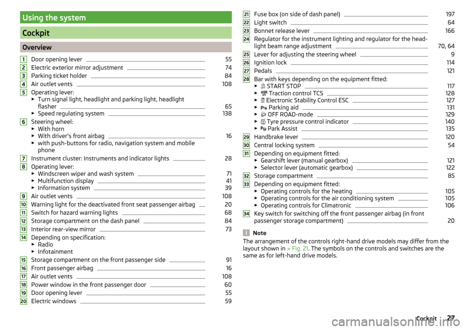
OverviewDoor opening lever
55
Electric exterior mirror adjustment
74
Parking ticket holder
84
Air outlet vents
108
Operating lever:
▶ Turn signal light, headlight and parking light, headlight
flasher
65
▶ Speed regulating system
138
Steering wheel:
▶ With horn
▶ With driver’s front airbag
16
▶with push-buttons for radio, navigation system and mobile
phone
Instrument cluster: Instruments and indicator lights
28
Operating lever:
▶ Windscreen wiper and wash system
71
▶Multifunction display
41
▶Information system
39
Air outlet vents
108
Warning light for the deactivated front seat passenger airbag
20
Switch for hazard warning lights
68
Storage compartment on the dash panel
84
Interior rear-view mirror
73
Depending on specification:
▶ Radio
▶ Infotainment
Storage compartment on the front passenger side
91
Front passenger airbag
16
Air outlet vents
108
Power window in the front passenger door
60
Door opening lever
55
Electric windows
591234567891011121314151617181920Fuse box (on side of dash panel)197
Light switch
64
Bonnet release lever
166
Regulator for the instrument lighting and regulator for the head-
light beam range adjustment
70, 64
Lever for adjusting the steering wheel
9
Ignition lock
114
Pedals
121
Bar with keys depending on the equipment fitted:
▶ START STOP
117
▶
Traction control TCS
128
▶
Electronic Stability Control ESC
127
▶
Parking aid
131
▶
OFF ROAD-mode
129
▶
Tyre pressure control indicator
140
▶
Park Assist
135
Handbrake lever
120
Central locking system
54
Depending on equipment fitted:
▶ Gearshift lever (manual gearbox)
121
▶Selector lever (automatic gearbox)
122
Storage compartment
85
Depending on equipment fitted:
▶ Operating controls for the heating
105
▶Operating controls for the air conditioning system
105
▶Operating controls for Climatronic
106
Key switch for switching off the front passenger airbag (in front
passenger storage compartment)
20
Note
The arrangement of the controls right-hand drive models may differ from the
layout shown in » Fig. 21. The symbols on the controls and switches are the
same as for left-hand drive models.212223242526272829303132333427Cockpit
Page 125 of 232
Fault in the automatic gearbox
A fault in the automatic gearbox can, for example, be noticeable by the follow-
ing.
▶ Only certain gears are selected.
▶ The reverse gear R cannot be used.
▶ Shifting gears in Tiptronic mode is not possible.
CAUTION
If an error occurs on the automatic transmission the help of a specialist firm
should be sought immediately - there is a risk of damaging the vehicle.
Selector lever lock
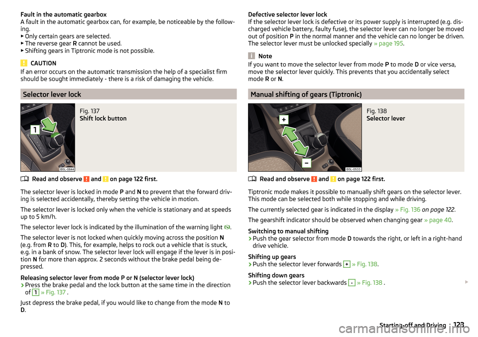
Fig. 137
Shift lock button
Read and observe and on page 122 first.
The selector lever is locked in mode P and N to prevent that the forward driv-
ing is selected accidentally, thereby setting the vehicle in motion.
The selector lever is locked only when the vehicle is stationary and at speeds
up to 5 km/h.
The selector lever lock is indicated by the illumination of the warning light
.
The selector lever is not locked when quickly moving across the position N
(e.g. from R to D). This, for example, helps to rock out a vehicle that is stuck,
e.g. in a bank of snow. The selector lever lock will engage if the lever is in posi-
tion N for more than approx. 2 seconds without the brake pedal being de-
pressed.
Releasing selector lever from mode P or N (selector lever lock)
›
Press the brake pedal and the lock button at the same time in the direction
of
1
» Fig. 137 .
Just depress the brake pedal, if you would like to change from the mode N to
D .
Defective selector lever lock
If the selector lever lock is defective or its power supply is interrupted (e.g. dis-
charged vehicle battery, faulty fuse), the selector lever can no longer be moved
out of position P in the normal manner and the vehicle can no longer be driven.
The selector lever must be unlocked specially » page 195.
Note
If you want to move the selector lever from mode P to mode D or vice versa,
move the selector lever quickly. This prevents that you accidentally select
mode R or N.
Manual shifting of gears (Tiptronic)
Fig. 138
Selector lever
Read and observe and on page 122 first.
Tiptronic mode makes it possible to manually shift gears on the selector lever.
This mode can be selected both while stopping and while driving.
The currently selected gear is indicated in the display » Fig. 136 on page 122 .
The gearshift indicator should be observed when changing gear » page 40.
Switching to manual shifting
›
Push the gear selector from mode D towards the right, or left in a right-hand
drive vehicle.
Shifting up gears
›
Push the selector lever forwards
+
» Fig. 138 .
Shifting down gears
›
Push the selector lever backwards
-
» Fig. 138 .
123Starting-off and Driving
Page 199 of 232
CAUTION■“Never repair” fuses, and do not replace them with fuses of a higher amper-
age – risk of fire! This may also cause damage at another part of the electrical
system.■
If a newly inserted fuse blows again after a short time, have the electrical
system checked as quickly as possible by a specialist garage.
■
A blown fuses is recognisable by the molten metal strip. Replace the faulty
fuse with a new one of the same amperage.
Note
■
We recommend always carrying replacement fuses in the vehicle. A box of
replacement fuses and bulbs can be purchased from ŠKODA Original Accesso-
ries.■
There can be several power consuming devices for one fuse.
■
Multiple fuses may exist for a single power consuming device.
Fuses in the dash panel
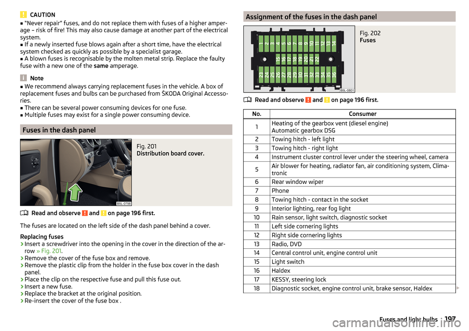
Fig. 201
Distribution board cover.
Read and observe and on page 196 first.
The fuses are located on the left side of the dash panel behind a cover.
Replacing fuses
›
Insert a screwdriver into the opening in the cover in the direction of the ar-
row » Fig. 201 .
›
Remove the cover of the fuse box and remove.
›
Remove the plastic clip from the holder in the fuse box cover in the dash
panel.
›
Place the clip on the respective fuse and pull this fuse out.
›
Insert a new fuse.
›
Replace the bracket at the original position.
›
Re-insert the cover of the fuse box .
Assignment of the fuses in the dash panelFig. 202
Fuses
Read and observe and on page 196 first.
No.Consumer1Heating of the gearbox vent (diesel engine)
Automatic gearbox DSG2Towing hitch - left light3Towing hitch - right light4Instrument cluster control lever under the steering wheel, camera5Air blower for heating, radiator fan, air conditioning system, Clima-
tronic6Rear window wiper7Phone8Towing hitch - contact in the socket9Interior lighting, rear fog light10Rain sensor, light switch, diagnostic socket11Left side cornering lights12Right side cornering lights13Radio, DVD14Central control unit, engine control unit15Light switch16Haldex17KESSY, steering lock18Diagnostic socket, engine control unit, brake sensor, Haldex 197Fuses and light bulbs
Page 200 of 232
No.Consumer19ABS, ESP, switch for tyre air pressure control, parking aid, switch for
OFF ROAD mode, START STOP button20Switch, airbag21WIV, tail lamp, dimming mirror, pressure sensor, telephone prepara-
tion, air mass sensor, headlight range control and headlight tilt22Instrument cluster, electromechanical power steering, databus23Central locking system and bonnet lid24Rear power window25Rear window heater, auxiliary heating and ventilation26Power socket in the boot27Panorama window - sliding / tilting roof, electric sunblind28Fuel pump, injectors, AdBlue ®
heating29Front power window30front and rear lighter31Headlight cleaning system32Front seat heating, regulator for seat heating33Heating, air conditioning, Climatronic, remote control for auxiliary
heating34Alarm, spare horn35Automatic gearbox DSG36Tow hitch
Fuses in the engine compartment
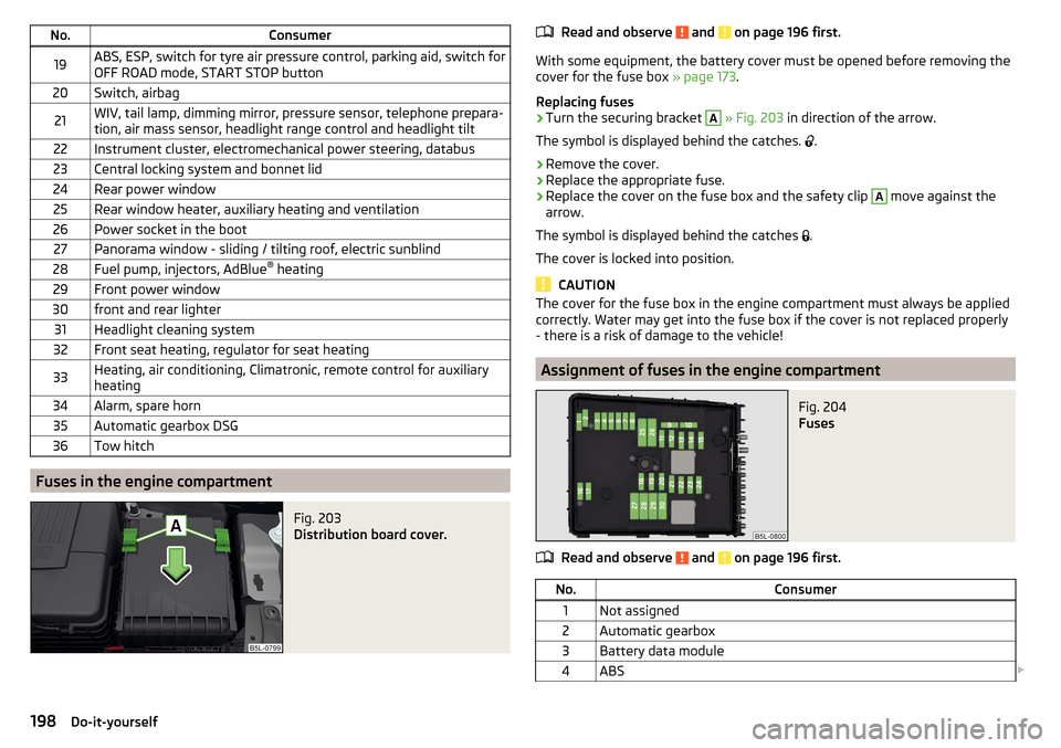
Fig. 203
Distribution board cover.
Read and observe and on page 196 first.
With some equipment, the battery cover must be opened before removing the
cover for the fuse box » page 173.
Replacing fuses
›
Turn the securing bracket
A
» Fig. 203 in direction of the arrow.
The symbol is displayed behind the catches.
.
›
Remove the cover.
›
Replace the appropriate fuse.
›
Replace the cover on the fuse box and the safety clip
A
move against the
arrow.
The symbol is displayed behind the catches .
The cover is locked into position.
CAUTION
The cover for the fuse box in the engine compartment must always be applied
correctly. Water may get into the fuse box if the cover is not replaced properly
- there is a risk of damage to the vehicle!
Assignment of fuses in the engine compartment
Fig. 204
Fuses
Read and observe and on page 196 first.
No.Consumer1Not assigned2Automatic gearbox3Battery data module4ABS 198Do-it-yourself
Page 201 of 232
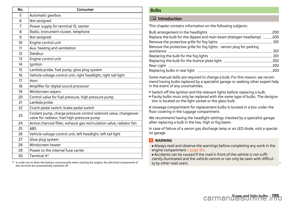
No.Consumer5Automatic gearbox6Not assigned7Power supply for terminal 15, starter8Radio, instrument cluster, telephone9Not assigned10Engine control unit11Aux. heating and ventilation12Databus13Engine control unit14Ignition15Lambda probe, fuel pump, glow plug system16Vehicle voltage control unit, right headlight, right tail light17Horn18Amplifier for digital sound processor19Windscreen wipers20Control valve for fuel pressure, high pressure pump21Lambda probe22Clutch pedal switch, brake pedal switch23Coolant pump, charge pressure control solenoid valve, changeover
valve for radiator, fuel high-pressure pump24Active charcoal filter, exhaust gas recirculation valve, radiator fan25ABS26Vehicle voltage control unit, left headlight, left tail light27Glow plug system28Windscreen heater29Power to the internal fuse carrier30Terminal X a)a)
In order not to drain the battery unnecessarily when starting the engine, the electrical components of
this terminal are automatically switched off.
Bulbs
Introduction
This chapter contains information on the following subjects:
Bulb arrangement in the headlights
200
Replace the bulb for the dipped and main beam (Halogen headlamp)
200
Remove the protective grille for fog lights
201
Remove the protective grille for fog lights - sensor plug for parking
assistance
201
Replacing the bulb for the fog lights
201
Replacing the bulb for the licence plate light
202
Rear Light
202
Replacing bulbs in rear light
203
Some manual skills are required to change a bulb. For this reason, we recom-
mend having bulbs replaced by a specialist garage or seeking other expert help
in the event of any uncertainties.
▶ Switch off the ignition and the relevant lights before replacing a bulb.
▶ Faulty bulbs must only be replaced with the same type of bulbs. The designa-
tion is located on the light socket or the glass bulb.
A stowage compartment for replacement bulbs is located in a box under the floor covering in the luggage compartment.
We recommend having the headlight settings checked by a specialist garage after replacing a bulb in the low, high or fog beam.
In case of failure of a xenon gas discharge lamp or an LED diode, visit a special- ist garage.
WARNING■ Always read and observe the warnings before completing any work in the
engine compartment » page 165.■
Accidents can be caused if the road in front of the vehicle is not suffi-
ciently illuminated and the vehicle cannot or can only be seen with difficul-
ty by other road users.
199Fuses and light bulbs
Page 222 of 232
rear seatsin the longitudinal direction81
Rear seats80
Fold back82
fold down seat back81
Fold down seat fully81
Removing seats82
Setting outer seat in the transverse direction82
Rear View Camera133
Function keys134
Operation134
Orientation Lines134
Rear view mirror Interior mirror
73
Rear window - heater70
Refuelling160
Fuel160
Remote control Locking
53
Replacing the battery193
Synchronisation process193
Unlocking53
Remote control key Replacing the battery
193
Removable light Removing light
101
replace batteries of the lights193
Removable through-loading bag93
Removing the variable loading floor
102
Repairs and technical alterations149
Replace Bulb for dipped beam (Halogen headlamp)
200
Bulb for main beam (Halogen headlamp)200
the battery in the auxiliary heating (auxiliary heating) in the remote control
193
replace - batteries of the lights193
Replacing bulb for fog lights
201
Bulb for the licence plate light202
Bulb in rear light203
Bulbs199
Fuses196
Fuses in the dash panel197
Fuses in the engine compartment198
Vehicle battery175
windscreen wiper blades195
Replacing windscreen wiper blades195
Replenishing Coolant
171
Engine oil169
Windscreen washer fluid167
Reversing camera Lens care
156
Revolutions counter29
Roof Load
104
Roof rack103
Roof load104
Rubber seals155
Running-in Brake linings
124
Engine124
Tyres124
S
SAFE See Safe securing system
54
SAFELOCK See Safe securing system
54
Safe securing system54
Safety8
Child safety21
Child safety seats21
Correct seated position8
Head restraints79
ISOFIX23
TOP TETHER25
Safety belts rear middle seat
13
Save electrical energy125
Save fuel125
Seals Vehicle care
155
Seat Front seat adjustment
75
Seat belt height adjustment
12
warning light33
Seat belts11
Belt tensioners14
fastening and unfastening13
Seatbelts Inertia reels
14
Seat belts The physical principle of a head-on collision
12
Seat electrical adjustment76
Seat functions78
Seats Electrical adjustment
76
Folding front passenger seat79
Front armrest78
Head restraints79
Heating78
Manual adjustment76
Memory Function of the electrically adjustable seat
76
Storing in memory of remote control key77
Seats and head restraint75
Securing the variable load floor in the raised position
103
Selector lever Refer to Selector lever
122
Selector lever lock (automatic gearbox) Warning light
39
Service150
Service interval display48
Setting Seat belt height
12
220Index