gas type SKODA YETI 2015 1.G / 5L Owner's Manual
[x] Cancel search | Manufacturer: SKODA, Model Year: 2015, Model line: YETI, Model: SKODA YETI 2015 1.G / 5LPages: 232, PDF Size: 30.84 MB
Page 9 of 232

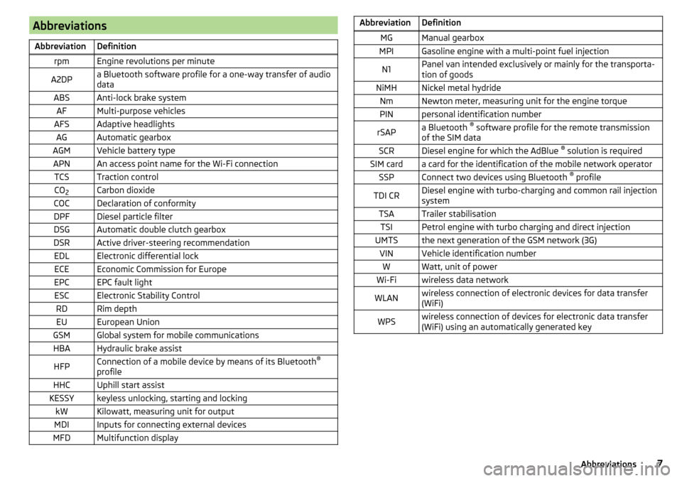
AbbreviationsAbbreviationDefinitionrpmEngine revolutions per minuteA2DPa Bluetooth software profile for a one-way transfer of audio
dataABSAnti-lock brake systemAFMulti-purpose vehiclesAFSAdaptive headlightsAGAutomatic gearboxAGMVehicle battery typeAPNAn access point name for the Wi-Fi connectionTCSTraction controlCO 2Carbon dioxideCOCDeclaration of conformityDPFDiesel particle filterDSGAutomatic double clutch gearboxDSRActive driver-steering recommendationEDLElectronic differential lockECEEconomic Commission for EuropeEPCEPC fault lightESCElectronic Stability ControlRDRim depthEUEuropean UnionGSMGlobal system for mobile communicationsHBAHydraulic brake assistHFPConnection of a mobile device by means of its Bluetooth ®
profileHHCUphill start assistKESSYkeyless unlocking, starting and lockingkWKilowatt, measuring unit for outputMDIInputs for connecting external devicesMFDMultifunction displayAbbreviationDefinitionMGManual gearboxMPIGasoline engine with a multi-point fuel injectionN1Panel van intended exclusively or mainly for the transporta-
tion of goodsNiMHNickel metal hydrideNmNewton meter, measuring unit for the engine torquePINpersonal identification numberrSAPa Bluetooth ®
software profile for the remote transmission
of the SIM dataSCRDiesel engine for which the AdBlue ®
solution is requiredSIM carda card for the identification of the mobile network operatorSSPConnect two devices using Bluetooth ®
profileTDI CRDiesel engine with turbo-charging and common rail injection
systemTSATrailer stabilisationTSIPetrol engine with turbo charging and direct injectionUMTSthe next generation of the GSM network (3G)VINVehicle identification numberWWatt, unit of powerWi-Fiwireless data networkWLANwireless connection of electronic devices for data transfer
(WiFi)WPSwireless connection of devices for electronic data transfer
(WiFi) using an automatically generated key7Abbreviations
Page 17 of 232

Airbag system
Description of the airbag system
Introduction
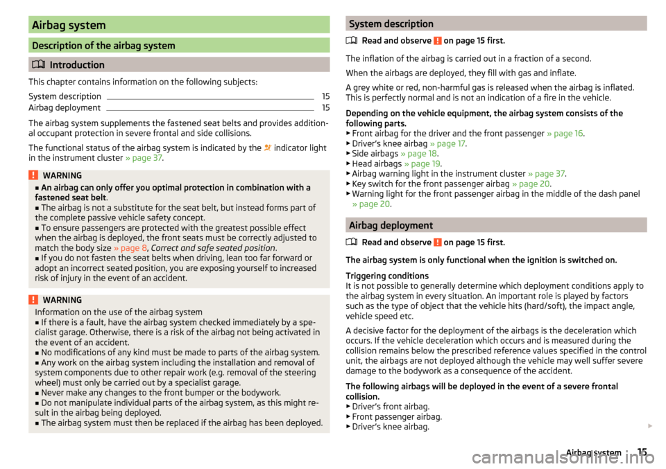
This chapter contains information on the following subjects:
System description
15
Airbag deployment
15
The airbag system supplements the fastened seat belts and provides addition-
al occupant protection in severe frontal and side collisions.
The functional status of the airbag system is indicated by the indicator light
in the instrument cluster » page 37.
WARNING■
An airbag can only offer you optimal protection in combination with a
fastened seat belt .■
The airbag is not a substitute for the seat belt, but instead forms part of
the complete passive vehicle safety concept.
■
To ensure passengers are protected with the greatest possible effect
when the airbag is deployed, the front seats must be correctly adjusted to
match the body size » page 8, Correct and safe seated position .
■
If you do not fasten the seat belts when driving, lean too far forward or
adopt an incorrect seated position, you are exposing yourself to increased
risk of injury in the event of an accident.
WARNINGInformation on the use of the airbag system■If there is a fault, have the airbag system checked immediately by a spe-
cialist garage. Otherwise, there is a risk of the airbag not being activated in
the event of an accident.■
No modifications of any kind must be made to parts of the airbag system.
■
Any work on the airbag system including the installation and removal of
system components due to other repair work (e.g. removal of the steering
wheel) must only be carried out by a specialist garage.
■
Never make any changes to the front bumper or the bodywork.
■
Do not manipulate individual parts of the airbag system, as this might re-
sult in the airbag being deployed.
■
The airbag system must then be replaced if the airbag has been deployed.
System description
Read and observe
on page 15 first.
The inflation of the airbag is carried out in a fraction of a second.
When the airbags are deployed, they fill with gas and inflate.
A grey white or red, non-harmful gas is released when the airbag is inflated.
This is perfectly normal and is not an indication of a fire in the vehicle.
Depending on the vehicle equipment, the airbag system consists of the
following parts. ▶ Front airbag for the driver and the front passenger » page 16.
▶ Driver’s knee airbag » page 17.
▶ Side airbags » page 18.
▶ Head airbags » page 19.
▶ Airbag warning light in the instrument cluster » page 37.
▶ Key switch for the front passenger airbag » page 20.
▶ Warning light for the front passenger airbag in the middle of the dash panel
» page 20 .
Airbag deployment
Read and observe
on page 15 first.
The airbag system is only functional when the ignition is switched on.
Triggering conditions
It is not possible to generally determine which deployment conditions apply to
the airbag system in every situation. An important role is played by factors
such as the type of object that the vehicle hits (hard/soft), the impact angle, vehicle speed etc.
A decisive factor for the deployment of the airbags is the deceleration which
occurs. If the vehicle deceleration which occurs and is measured during the
collision remains below the prescribed reference values specified in the control
unit, the airbags are not deployed although the vehicle may well suffer severe
damage to the bodywork as a consequence of the accident.
The following airbags will be deployed in the event of a severe frontal
collision.
▶ Driver’s front airbag.
▶ Front passenger airbag.
▶ Driver’s knee airbag.
15Airbag system
Page 201 of 232

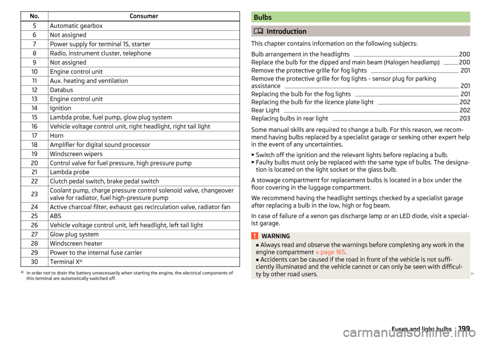
No.Consumer5Automatic gearbox6Not assigned7Power supply for terminal 15, starter8Radio, instrument cluster, telephone9Not assigned10Engine control unit11Aux. heating and ventilation12Databus13Engine control unit14Ignition15Lambda probe, fuel pump, glow plug system16Vehicle voltage control unit, right headlight, right tail light17Horn18Amplifier for digital sound processor19Windscreen wipers20Control valve for fuel pressure, high pressure pump21Lambda probe22Clutch pedal switch, brake pedal switch23Coolant pump, charge pressure control solenoid valve, changeover
valve for radiator, fuel high-pressure pump24Active charcoal filter, exhaust gas recirculation valve, radiator fan25ABS26Vehicle voltage control unit, left headlight, left tail light27Glow plug system28Windscreen heater29Power to the internal fuse carrier30Terminal X a)a)
In order not to drain the battery unnecessarily when starting the engine, the electrical components of
this terminal are automatically switched off.
Bulbs
Introduction
This chapter contains information on the following subjects:
Bulb arrangement in the headlights
200
Replace the bulb for the dipped and main beam (Halogen headlamp)
200
Remove the protective grille for fog lights
201
Remove the protective grille for fog lights - sensor plug for parking
assistance
201
Replacing the bulb for the fog lights
201
Replacing the bulb for the licence plate light
202
Rear Light
202
Replacing bulbs in rear light
203
Some manual skills are required to change a bulb. For this reason, we recom-
mend having bulbs replaced by a specialist garage or seeking other expert help
in the event of any uncertainties.
▶ Switch off the ignition and the relevant lights before replacing a bulb.
▶ Faulty bulbs must only be replaced with the same type of bulbs. The designa-
tion is located on the light socket or the glass bulb.
A stowage compartment for replacement bulbs is located in a box under the floor covering in the luggage compartment.
We recommend having the headlight settings checked by a specialist garage after replacing a bulb in the low, high or fog beam.
In case of failure of a xenon gas discharge lamp or an LED diode, visit a special- ist garage.
WARNING■ Always read and observe the warnings before completing any work in the
engine compartment » page 165.■
Accidents can be caused if the road in front of the vehicle is not suffi-
ciently illuminated and the vehicle cannot or can only be seen with difficul-
ty by other road users.
199Fuses and light bulbs