boot SKODA YETI 2016 1.G / 5L Owner's Guide
[x] Cancel search | Manufacturer: SKODA, Model Year: 2016, Model line: YETI, Model: SKODA YETI 2016 1.G / 5LPages: 200, PDF Size: 28.98 MB
Page 119 of 200
OperationFig. 137
Installation location of the camera / scanned area behind the ve-
hicle
Read and observe
and on page 116 first.
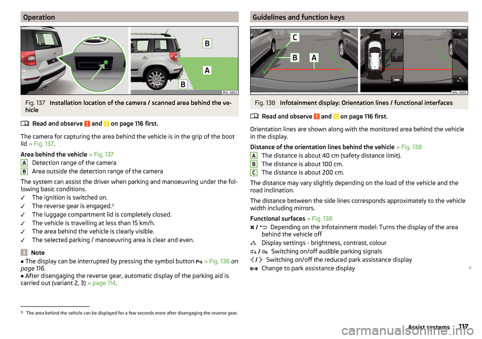
The camera for capturing the area behind the vehicle is in the grip of the boot
lid » Fig. 137 .
Area behind the vehicle » Fig. 137
Detection range of the camera
Area outside the detection range of the camera
The system can assist the driver when parking and manoeuvring under the fol- lowing basic conditions.
The ignition is switched on.
The reverse gear is engaged. 1)
The luggage compartment lid is completely closed.
The vehicle is travelling at less than 15 km/h.
The area behind the vehicle is clearly visible.
The selected parking / manoeuvring area is clear and even.
Note
■ The display can be interrupted by pressing the symbol button » Fig. 136 on
page 116 .■
After disengaging the reverse gear, automatic display of the parking aid is
carried out (variant 2, 3) » page 114.
ABGuidelines and function keysFig. 138
Infotainment display: Orientation lines / functional interfaces
Read and observe
and on page 116 first.
Orientation lines are shown along with the monitored area behind the vehicle
in the display.
Distance of the orientation lines behind the vehicle » Fig. 138
The distance is about 40 cm (safety distance limit).
The distance is about 100 cm.
The distance is about 200 cm.
The distance may vary slightly depending on the load of the vehicle and the
road inclination.
The distance between the side lines corresponds approximately to the vehicle
width including mirrors.
Functional surfaces » Fig. 138
Depending on the Infotainment model: Turns the display of the area
behind the vehicle off
Display settings - brightness, contrast, colour Switching on/off audible parking signals
Switching on/off the reduced park assistance display
Change to park assistance display
ABC
1)
The area behind the vehicle can be displayed for a few seconds more after disengaging the reverse gear.
117Assist systems
Page 129 of 200
›Remover the cover A from the handwheel lock in the direction of the arrow1
» Fig. 149 .›
Insert the key into the handwheel lock.
›
Turn the key
B
2
in the direction of the arrow as far as the stop.
Removing ball rod - Step 2
Fig. 150
Removing the two bar/placing the cover on the rear bumper
Read and observe
on page 124 first.
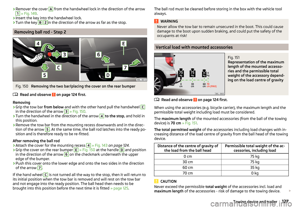
Removing
›
Grip the tow bar from below and with the other hand pull the handwheel
C
in the direction of the arrow
3
» Fig. 150 .
›
Turn the handwheel in the direction of the arrow
4
to the stop , and hold in
this position.
›
Remove the tow bar from the mounting recess downwards and in the direc-
tion of the arrow
5
. At the same time, the ball rod latches into the ready po-
sition and is therefore ready to be re-fitted.
After removing the ball rod
›
Attach the cover for the mounting recess
4
» Fig. 143 on page 124 .
›
Grip the cover on the rear bumper
E
» Fig. 150 at the handle
D
and position
in the direction of the arrow
6
on the checkmark underneath the upper
edge of the bumper.
›
Push this cover onto the lower edge and onto the two sides in the direction
of the arrow
7
.
If the hand wheel
C
is not turned all the way to the stop, then it will return to
its initial position when the tow bar is removed and will rest on the tow bar
and not engage into the ready position. The ball head then needs to be
brought into this position before the next time it is fitted » page 125.
The ball rod must be cleaned before storing in the box with the vehicle tool
always.WARNINGNever allow the tow bar to remain unsecured in the boot. This could cause
damage to the boot upon sudden braking, and could put the safety of the
occupants at risk!
Vertical load with mounted accessories
Fig. 151
Representation of the maximum
length of the mounted accesso-
ries and the permissible total
weight of the accessory depend-
ing on the load centre of gravity
Read and observe on page 124 first.
When using the accessories (e.g. bicycle carrier), the maximum length and the
permissible total weight including load must be considered.
The maximum length of the mounted accessories (from the ball of the towing
device) is 70 cm » Fig. 151 .
The total permitted weight of the accessories including load changes with in-
creasing distance of the load centre of gravity from the ball head of the towing
device.
Distance of the centre of gravity of the load from the ball headPermissible total weight of the ac- cessories, including load0 cm75 kg30 cm75 kg60 cm35 kg70 cm0 kg
CAUTION
Never exceed the permissible total weight of the accessories incl. load and
maximum length of the accessories - risk of damage to the towing device. 127Towing device and trailer
Page 134 of 200
ŠKODA Original partsRead and observe
on page 131 first.
We recommend the use of ŠKODA Genuine Parts for your vehicle, as these
parts are approved by ŠKODA AUTO. These parts comply wholly with ŠKODA
AUTO regulations and are identical to the parts used in series production.
ŠKODA AUTO is able to warrant the safety, suitability, and long life of these
products.
ŠKODA Service Partners are liable for any defects of ŠKODA Genuine Parts for
a period of 2 years after sale in accordance with the materials defect liability,
unless agreed otherwise in the purchase agreement.
ŠKODA Original accessories
Read and observe
on page 131 first.
If you wish to fit accessories to your vehicle, you should remember the follow-ing:
We recommend that you use ŠKODA Genuine Accessories in your vehicle.
ŠKODA AUTO has selected these accessories to ensure that they are reliable,
safe and suitable for your particular vehicle. Although we constantly monitor
the market, we are not able to assess or vouch the suitability of other products
for your vehicle, despite the fact that some products may have operational ap-
proval or may have been approved by a nationally recognised testing laborato-
ry.
ŠKODA Service Partners are liable for any defects of ŠKODA Genuine Accesso-
ries for a period of 2 years after installation or delivery in accordance with the
materials defect liability, unless agreed otherwise in the purchase agreement
or any other agreements.
Spoiler
Read and observe
on page 131 first.
WARNINGIf your vehicle is equipped with a Genuine Accessories spoiler on the front
bumper in combination with the spoiler on the boot lid, the following in-
structions must be observed - otherwise there is a risk of accidents and se-
rious injuries!■
The vehicle can only be equipped with a spoiler on the front bumper in
combination with the corresponding spoiler on the boot lid.
■
A Genuine Accessories spoiler cannot be fitted to the front bumper either
on its own (without a spoiler on the boot lid) or in combination with an un-
suitable spoiler on the boot lid.
■
We recommend that you consult the ŠKODA Service Partner for any re-
pairs to or replacement, addition or removal of spoilers.
■
Unprofessional work carried out on the spoilers of your vehicle may result
in some functions/vehicle systems malfunctioning.
Component protection
Read and observe
on page 131 first.
Some electronic vehicle components (such as the instrument cluster) are fac-
tory-equipped with component protection. This ensures the functional limita-
tion of these components in a non-legitimate installation in another vehicle
(e.g. after a theft) or operation outside the vehicle.
Airbags
Read and observe
on page 131 first.
WARNING■Modifications, repairs and technical alterations that have been carried out
unprofessionally can cause damage and operational faults, and can also se-
riously impair the effectiveness of the airbag system – risk of accident and
fatal injury!■
A change to the vehicle's wheel suspension, including the use of non-ap-
proved wheels and tire combinations, can impair the functioning of the air-
bag system - There is a risk of an accident and fatal injury!
132General Maintenance
Page 156 of 200
Do-it-yourself
Emergency equipment and self-help
Emergency equipment
Introduction
This chapter contains information on the following subjects:
Placement of the first aid kit and warning triangle
154
Location of reflective vest
154
Fire extinguisher
154
Vehicle tool kit
155
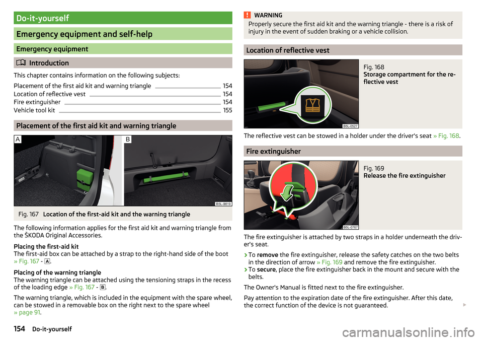
Placement of the first aid kit and warning triangle
Fig. 167
Location of the first-aid kit and the warning triangle
The following information applies for the first aid kit and warning triangle from the ŠKODA Original Accessories.
Placing the first-aid kit
The first-aid box can be attached by a strap to the right-hand side of the boot
» Fig. 167 -
.
Placing of the warning triangle
The warning triangle can be attached using the tensioning straps in the recess
of the loading edge » Fig. 167 -
.
The warning triangle, which is included in the equipment with the spare wheel,
can be stowed in a removable box on the right next to the spare wheel
» page 91 .
WARNINGProperly secure the first aid kit and the warning triangle - there is a risk of
injury in the event of sudden braking or a vehicle collision.
Location of reflective vest
Fig. 168
Storage compartment for the re-
flective vest
The reflective vest can be stowed in a holder under the driver's seat » Fig. 168.
Fire extinguisher
Fig. 169
Release the fire extinguisher
The fire extinguisher is attached by two straps in a holder underneath the driv-
er's seat.
›
To remove the fire extinguisher, release the safety catches on the two belts
in the direction of arrow » Fig. 169 and remove the fire extinguisher.
›
To secure , place the fire extinguisher back in the mount and secure with the
belts.
The Owner's Manual is fitted next to the fire extinguisher.
Pay attention to the expiration date of the fire extinguisher. After this date,
the correct function of the device is not guaranteed.
154Do-it-yourself
Page 167 of 200
›Lever off the cover for the rechargeable batteries with a narrow and pointed
object from the area of the lock clips A.›
Replace the batteries.
›
Insert the cover for the rechargeable batteries and press it down until it
clicks into place.
CAUTION
If an incorrect battery type is used or a non-rechargeable battery, there is a
risk of damaging the light and the vehicle's electrical system.
Emergency unlocking / unlocking of doors
Introduction
This chapter contains information on the following subjects:
Unlocking/locking the driver's door
165
Locking the door without locking cylinders
165
Unlock the boot lid
165
Selector lever-emergency unlocking
166
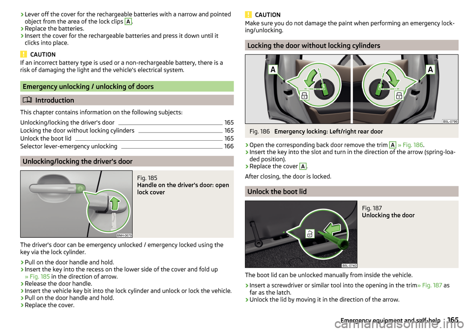
Unlocking/locking the driver's door
Fig. 185
Handle on the driver's door: open
lock cover
The driver's door can be emergency unlocked / emergency locked using the key via the lock cylinder.
›
Pull on the door handle and hold.
›
Insert the key into the recess on the lower side of the cover and fold up
» Fig. 185 in the direction of arrow.
›
Release the door handle.
›
Insert the vehicle key bit into the lock cylinder and unlock or lock the vehicle.
›
Pull on the door handle and hold.
›
Replace the cover.
CAUTIONMake sure you do not damage the paint when performing an emergency lock-
ing/unlocking.
Locking the door without locking cylinders
Fig. 186
Emergency locking: Left/right rear door
›
Open the corresponding back door remove the trim
A
» Fig. 186 .
›
Insert the key into the slot and turn in the direction of the arrow (spring-loa-
ded position).
›
Replace the cover
A
.
After closing, the door is locked.
Unlock the boot lid
Fig. 187
Unlocking the door
The boot lid can be unlocked manually from inside the vehicle.
›
Insert a screwdriver or similar tool into the opening in the trim » Fig. 187 as
far as the latch.
›
Unlock the lid by moving it in the direction of the arrow.
165Emergency equipment and self-help
Page 170 of 200
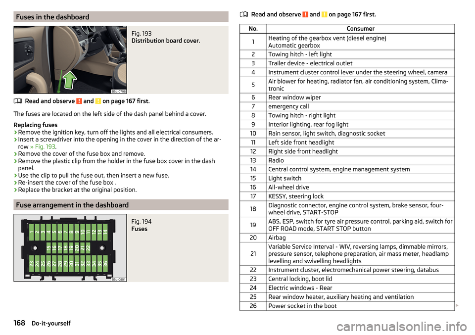
Fuses in the dashboardFig. 193
Distribution board cover.
Read and observe and on page 167 first.
The fuses are located on the left side of the dash panel behind a cover.
Replacing fuses
›
Remove the ignition key, turn off the lights and all electrical consumers.
›
Insert a screwdriver into the opening in the cover in the direction of the ar-
row » Fig. 193 .
›
Remove the cover of the fuse box and remove.
›
Remove the plastic clip from the holder in the fuse box cover in the dash
panel.
›
Use the clip to pull the fuse out, then insert a new fuse.
›
Re-insert the cover of the fuse box .
›
Replace the bracket at the original position.
Fuse arrangement in the dashboard
Fig. 194
Fuses
Read and observe and on page 167 first.No.Consumer1Heating of the gearbox vent (diesel engine)
Automatic gearbox2Towing hitch - left light3Trailer device - electrical outlet4Instrument cluster control lever under the steering wheel, camera5Air blower for heating, radiator fan, air conditioning system, Clima-
tronic6Rear window wiper7emergency call8Towing hitch - right light9Interior lighting, rear fog light10Rain sensor, light switch, diagnostic socket11Left side front headlight12Right side front headlight13Radio14Central control system, engine management system15Light switch16All-wheel drive17KESSY, steering lock18Diagnostic connector, engine control system, brake sensor, four-
wheel drive, START-STOP19ABS, ESP, switch for tyre air pressure control, parking aid, switch for
OFF ROAD mode, START STOP button20Airbag21Variable Service Interval - WIV, reversing lamps, dimmable mirrors,
pressure sensor, telephone preparation, air mass meter, headlamp
levelling and swivelling headlights22Instrument cluster, electromechanical power steering, databus23Central locking, boot lid24Electric windows - Rear25Rear window heater, auxiliary heating and ventilation26Power socket in the boot 168Do-it-yourself
Page 175 of 200

CAUTIONFor vehicles with parking assistance, we recommend that after changing the
light bulb in the fog lights, the system is checked by a specialist.
Changing the bulb for the licence plate light
Fig. 203
Remove / replace the bulb for the number plate light
Read and observe
and on page 170 first.
›
Open the boot lid.
›
Push the light in the direction of arrow
1
» Fig. 203 until it comes loose.
›
Swivel out the lamp in the direction of the arrow
2
and remove it.
›
Remove the faulty bulb from the holder in the direction of the arrow
3
.
›
Insert a new bulb into the holder.
›
Reinsert the lamp in the opposite direction to the arrow
1
.
›
Push on the light until the spring clicks into place.
›
Close the boot lid.
Removing/installing taillightsFig. 204
Remove light / pull out connector
Read and observe
and on page 170 first.
Removing
›
Open the boot lid.
›
Use the screwdriver from the tool kit to unscrew the lamp » Fig. 204.
›
Grasp the light and carefully remove with shaky movements in the direction
of arrow
1
» Fig. 204 .
›
Disconnect the plug connection by pressing the catches in direction of arrow
2
and by pulling them in direction of arrow
3
.
Fitting
›
Insert the connector into the light and lock it securely.
›
Insert the light into the mounts in the body » Fig. 204.
›
Carefully press the light into the body so that the bolts
1
» Fig. 205 on
page 174 or » Fig. 206 on page 174 on the light engage into the mounts on
the body »
.
›
Screw the light with the screws into place » Fig. 204.
›
Close the boot lid.
CAUTION
Ensure that the vehicle paintwork and the tail lamp are not damaged when re-
moving and installing the tail lamp.173Fuses and light bulbs
Page 186 of 200

Index
A
ABS Operation
110
Warning light34
Acceptance and recycling of used vehicles
133
Accessories131
Adaptive headlight see xenon headlight
60
AdBlue141
Check level141
indicator light30
refill142
Adjusting Steering wheel
11
Adjusting seats manually68
Adjusting the seats10
Advice on tyre/wheel usage150
AFS Display messages
34
Warning light34
AHL see xenon headlight
60
Air-conditioning system Air outlet vents
96
Airbag
16
Adjustments and impairments to the airbag system
132
Deactivation19
Deployment17
Warning light36
Airbag system16
Air conditioning93
Air distribution control96
Climatronic94
Manual air conditioning94
Air distribution control96
Air outlet vents96
Alarm51
Trailer130
All-year tyres152
Alternator Warning light
32
Anti-lock braking system (ABS)110
Anti-theft alarm system51
Trailer130
Anti-theft wheel bolts157
Armrest Front
71
Ashtray78
Assist systems110
Auto Check Control30
Automatic drive Selector lever
106
Automatic driving light control60
Automatic gearbox Kickdown
108
Selector lever-emergency unlocking166
Selector lever lock107
Starting-off and driving108
Tiptronic107
Automatic shutdown of consumers147
Automatic transmission106
Selector lever lock107
AUX77
Auxiliary heating (auxiliary heating and ventila- tion)
97
Avoiding damage to your vehicle109
B
Bar with sliding hook
88
Battery Changing batteries for the removable light
164
Changing in key164
Replace the battery in the remote control in the auxiliary heating
164
Belts13
Belt tensioners15
Bluetooth See Owner's Manual Infotainment
6
Bonnet Closing
143
Opening143
Boot Class N1 vehicles
91
See boot lid53
Boot lid Automatic locking
53
Open/Close53
Warning light32
Brake Assist (HBA)111
Brake booster103
Brake fluid147
Check147
specification147
Brake pads New
103
Brake pedal (automatic transmission) Warning light
37
Brakes Brake booster
103
Brake fluid147
Braking and stabilisation systems110
Handbrake104
Information on braking103
Warning lights32
Brake system110
Breakdown kit159
Breakdown service see Help in an emergency
8
Bulbs Replacing
170
Buttons in the door Electric window
54
184Index
Page 187 of 200
C
Camera See reversing camera
116
Car battery Check condition
148
Cover148
Disconnecting and reconnecting149
Replacing149
Winter operation148
Car care Exterior
136
Interior138
Car computer See multifunction display
41
Care and maintenance131
Carrier93
Car washing135
Exterior136
Interior138
Washing135
Central locking47
Problems51
Central locking button49
Changing Batteries for the removable light
164
Battery164
Windscreen wiper blades167
Changing a wheel155
Changing155
Changing gear Selector lever
106
Changing wheels Wheels
155
Charging a vehicle battery149
Check Brake fluid
147
Engine oil145
Fasten ball rod properly126
Oil level145
Checking Battery status148
Coolant146
Checks Statutory checks
131
Children and safety21
Child safety lock51
Child seat21
Classification23
Installation location23, 24
ISOFIX24
on the front passenger seat22, 23
TOP TETHER25
Cigarette lighter78
Climatronic air distribution control
96
Automatic operation95
Operating elements94
Clothes hook82
Cockpit27
Lighting62
Comfort control window
55
Comfort signalling59
COMING HOME61
Compartments75
Component protection132
Computer See multifunction display
41
Convenience operation sliding / tilting roof
57
Coolant146
Checking146
Refilling146
Temperature display29
Warning light32
CORNER See Fog lights with the CORNER function
61
Cornering lightsDisplay messages34
Correct routing of seat belt
14
Correct seated position10
Correct seating position12
Cruise control system Warning light
37
Cruise Control System121
Cup holders77
D
DAY LIGHT see Daylight running lights
59
Daylight running lights59
Deactivation Airbag
19
Delayed locking of the boot lid See boot lid
53
Departure angle179
Diesel140
Diesel fuel140
Diesel particle filter (DPF)35
Digital Clock39
Digital Service Plan135
Dipped beam58
Dipstick145
Display Cardinal points
38
Coolant temperature29
Fuel level29
Gear changes39
In the instrument cluster38
Service intervals44
Display MAXI DOT42
Display of the second speed39
Display of the second speedometer39
Disposal Acceptance and recycling of used vehicles
133
185Index
Page 190 of 200

LockIndividual settings50
Key48
Locking Central locking button
49
in case of emergency165
KESSY49
Remote control48
Lock steering lock100
Low tyre pressure warning refer to the tyre pressure monitoring
123
Luggage compartment Cover
89
Fastening elements87
Fastening with sliding hook88
Fixing nets87
Flexible storage compartment88
Floor covering on both sides88
Net partition89
Side compartments90
unlock manually165
Unlock the boot lid165
Variable loading floor91
Luggage compartment cover89
Luggage compartment lid52
Luggage Storage86
lighting90
removable lamp90
M
Main beam
59
Warning light37
Manual air conditioning Air distribution control
96
Controls94
Manual gear changing see gear changing
105
Materials defect liability4
MAXI DOT See MAXI DOT display
42
MAXI DOT displayMain menu42
Menu item assist systems43
Menu item Audio43
Menu item navigation42
Menu item phone43
Operation40
Settings43
Mechanical window Open and close
54
Media AUX
77
See Owner's Manual Infotainment6
USB77
Memory42
Memory Function for the seat69
MFD See multifunction display
41
Mirror66
Vanity64
mobility warranty5
Modes of the automatic transmission106
Modifications and technical alterations131
MSR110
Multifunction display Functions
41
Information41
Memory42
Multifunction pocket87
Multifunction steering wheel40
Multimedia holder80
N
N1
91
Nameplate175
Navigation See Owner's Manual Infotainment
6
Net partition89
Nets87
O
OFF ROAD
112
ABS113
EDS113
hill descent assistant113
operation112
Start-Off Assistant114
TCS113
OFF ROAD mode warning light
37
OFF ROAD Mode112
oil See engine oil
145
Oil Information messages
33
Oil changing Engine oil
144
Oil pressure Information messages
33
On-board computer See multifunction display
41
Operating weight176
Original accessories132
Overview Cockpit
27
Engine compartment144
Fuses167
Warning lights31
P
Park assist Departing from a parallel parking space
120
Parking120
Park Assist118
Automatic brake assist121
Malfunctions121
Operation118
Parking space search119
188Index