adblue SKODA YETI 2016 1.G / 5L Owner's Manual
[x] Cancel search | Manufacturer: SKODA, Model Year: 2016, Model line: YETI, Model: SKODA YETI 2016 1.G / 5LPages: 200, PDF Size: 28.98 MB
Page 4 of 200
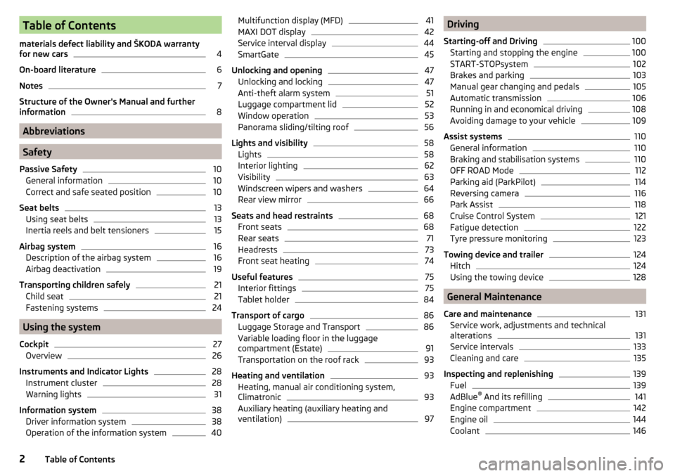
Table of Contents
materials defect liability and ŠKODA warranty
for new cars4
On-board literature
6
Notes
7
Structure of the Owner's Manual and further
information
8
Abbreviations
Safety
Passive Safety
10
General information
10
Correct and safe seated position
10
Seat belts
13
Using seat belts
13
Inertia reels and belt tensioners
15
Airbag system
16
Description of the airbag system
16
Airbag deactivation
19
Transporting children safely
21
Child seat
21
Fastening systems
24
Using the system
Cockpit
27
Overview
26
Instruments and Indicator Lights
28
Instrument cluster
28
Warning lights
31
Information system
38
Driver information system
38
Operation of the information system
40Multifunction display (MFD)41MAXI DOT display42
Service interval display
44
SmartGate
45
Unlocking and opening
47
Unlocking and locking
47
Anti-theft alarm system
51
Luggage compartment lid
52
Window operation
53
Panorama sliding/tilting roof
56
Lights and visibility
58
Lights
58
Interior lighting
62
Visibility
63
Windscreen wipers and washers
64
Rear view mirror
66
Seats and head restraints
68
Front seats
68
Rear seats
71
Headrests
73
Front seat heating
74
Useful features
75
Interior fittings
75
Tablet holder
84
Transport of cargo
86
Luggage Storage and Transport
86
Variable loading floor in the luggage
compartment (Estate)
91
Transportation on the roof rack
93
Heating and ventilation
93
Heating, manual air conditioning system,
Climatronic
93
Auxiliary heating (auxiliary heating and
ventilation)
97Driving
Starting-off and Driving100
Starting and stopping the engine
100
START-STOPsystem
102
Brakes and parking
103
Manual gear changing and pedals
105
Automatic transmission
106
Running in and economical driving
108
Avoiding damage to your vehicle
109
Assist systems
110
General information
110
Braking and stabilisation systems
110
OFF ROAD Mode
112
Parking aid (ParkPilot)
114
Reversing camera
116
Park Assist
118
Cruise Control System
121
Fatigue detection
122
Tyre pressure monitoring
123
Towing device and trailer
124
Hitch
124
Using the towing device
128
General Maintenance
Care and maintenance
131
Service work, adjustments and technical
alterations
131
Service intervals
133
Cleaning and care
135
Inspecting and replenishing
139
Fuel
139
AdBlue ®
And its refilling
141
Engine compartment
142
Engine oil
144
Coolant
1462Table of Contents
Page 11 of 200
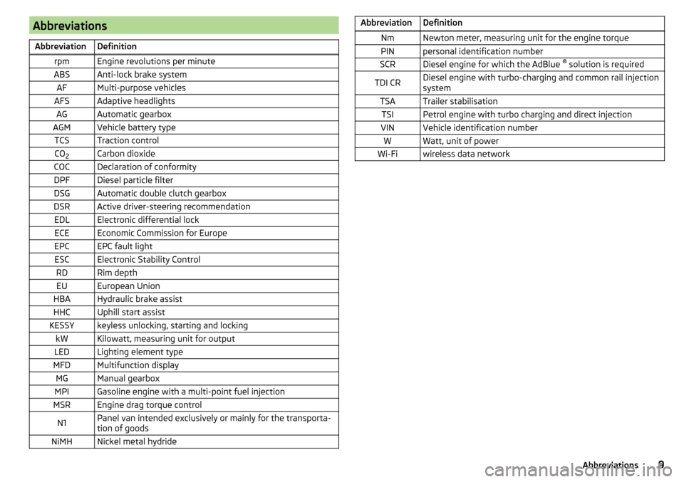
AbbreviationsAbbreviationDefinitionrpmEngine revolutions per minuteABSAnti-lock brake systemAFMulti-purpose vehiclesAFSAdaptive headlightsAGAutomatic gearboxAGMVehicle battery typeTCSTraction controlCO2Carbon dioxideCOCDeclaration of conformityDPFDiesel particle filterDSGAutomatic double clutch gearboxDSRActive driver-steering recommendationEDLElectronic differential lockECEEconomic Commission for EuropeEPCEPC fault lightESCElectronic Stability ControlRDRim depthEUEuropean UnionHBAHydraulic brake assistHHCUphill start assistKESSYkeyless unlocking, starting and lockingkWKilowatt, measuring unit for outputLEDLighting element typeMFDMultifunction displayMGManual gearboxMPIGasoline engine with a multi-point fuel injectionMSREngine drag torque controlN1Panel van intended exclusively or mainly for the transporta-
tion of goodsNiMHNickel metal hydrideAbbreviationDefinitionNmNewton meter, measuring unit for the engine torquePINpersonal identification numberSCRDiesel engine for which the AdBlue ®
solution is requiredTDI CRDiesel engine with turbo-charging and common rail injection
systemTSATrailer stabilisationTSIPetrol engine with turbo charging and direct injectionVINVehicle identification numberWWatt, unit of powerWi-Fiwireless data network9Abbreviations
Page 30 of 200
Instruments and Indicator Lights
Instrument cluster
Introduction
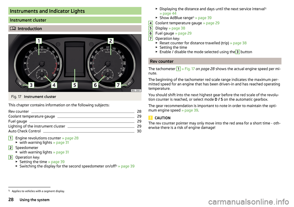
Fig. 17
Instrument cluster
This chapter contains information on the following subjects:
Rev counter
28
Coolant temperature gauge
29
Fuel gauge
29
Lighting of the instrument cluster
29
Auto Check Control
30
Engine revolutions counter » page 28
▶ with warning lights » page 31
Speedometer
▶ with warning lights » page 31
Operation key:
▶ Setting the time » page 39
▶ Switching the display for the second speedometer on/off 1)
» page 39
123▶
Displaying the distance and days until the next service interval 1)
» page 44
▶ Show AdBlue range 1)
» page 39
Coolant temperature gauge » page 29
Display » page 38
Fuel gauge » page 29
Operation key: ▶ Reset counter for distance travelled (trip) » page 38
▶ Setting the time
▶ Enable / disable the mode selected using the3
button
Rev counter
The tachometer
1
» Fig. 17 on page 28 shows the actual engine speed per mi-
nute.
The beginning of the tachometer red scale range indicates the maximum per-
mitted speed for an engine that has been driven-in and has reached operating
temperature.
You should shift into the next highest gear before the red scale of the revolu-
tion counter is reached, or select mode D / S on the automatic gearbox.
The gear recommendation is important to note in order to maintain the opti-
mum engine speed » page 39.
CAUTION
The rev counter pointer may only move into the red area for a short time - oth-
erwise there is a risk of engine damage!45671)
Applies to vehicles with a segment display.
28Using the system
Page 32 of 200
Auto Check Control
Vehicle condition
Certain functions and conditions of individual vehicle systems are checked
continuously when the ignition is switched on. If there is a system failure, the
relevant message is displayed in the MAXI DOTDisplay, in conjunction with in-
dicator lights, if necessary, indicator light illumination takes place in the instru-
ment cluster » page 31, Warning lights .
The menu item Vehicle status
is shown in the main menu of the MAXI DOT dis-
play whenever at least one fault message exists. After selecting this menu,
the first of the error messages is displayed.
Several error messages are shown on the display under the message e.g. 1/3.
This indicates that the first of a total of three error messages is being dis-
played.
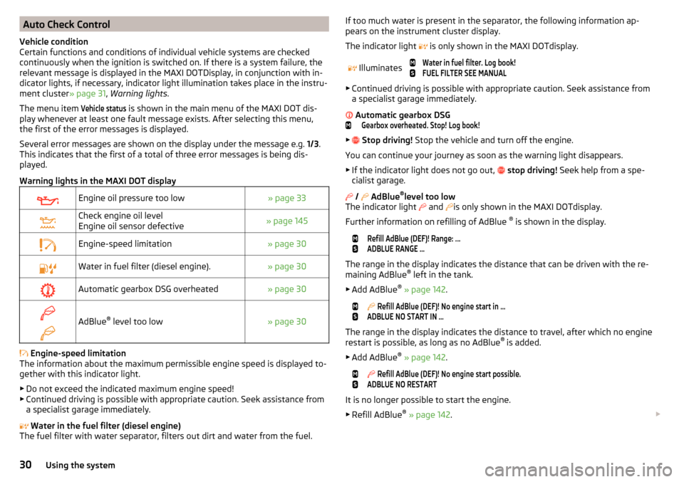
Warning lights in the MAXI DOT display
Engine oil pressure too low» page 33Check engine oil level
Engine oil sensor defective» page 145Engine-speed limitation» page 30Water in fuel filter (diesel engine).» page 30Automatic gearbox DSG overheated» page 30
AdBlue ®
level too low» page 30
Engine-speed limitation
The information about the maximum permissible engine speed is displayed to-
gether with this indicator light.
▶ Do not exceed the indicated maximum engine speed!
▶ Continued driving is possible with appropriate caution. Seek assistance from
a specialist garage immediately.
Water in the fuel filter (diesel engine)
The fuel filter with water separator, filters out dirt and water from the fuel.
If too much water is present in the separator, the following information ap-
pears on the instrument cluster display.
The indicator light is only shown in the MAXI DOTdisplay.
Illuminates
Water in fuel filter. Log book!FUEL FILTER SEE MANUAL
▶ Continued driving is possible with appropriate caution. Seek assistance from
a specialist garage immediately.
Automatic gearbox DSG
Gearbox overheated. Stop! Log book!
▶
Stop driving! Stop the vehicle and turn off the engine.
You can continue your journey as soon as the warning light disappears.
▶ If the indicator light does not go out,
stop driving! Seek help from a spe-
cialist garage.
/
AdBlue ®
level too low
The indicator light and
is only shown in the MAXI DOTdisplay.
Further information on refilling of AdBlue ®
is shown in the display.
Refill AdBlue (DEF)! Range: ...ADBLUE RANGE …
The range in the display indicates the distance that can be driven with the re-
maining AdBlue ®
left in the tank.
▶ Add AdBlue ®
» page 142 .
Refill AdBlue (DEF)! No engine start in …ADBLUE NO START IN …
The range in the display indicates the distance to travel, after which no engine
restart is possible, as long as no AdBlue ®
is added.
▶ Add AdBlue ®
» page 142 .
Refill AdBlue (DEF)! No engine start possible.ADBLUE NO RESTART
It is no longer possible to start the engine.
▶ Refill AdBlue ®
» page 142 .
30Using the system
Page 40 of 200
Information system
Driver information system
Introduction
This chapter contains information on the following subjects:
Display in the instrument cluster
38
Setting the time
39
Display of the second speedometer
39
Display of AdBlue range
39
Gear recommendation
39
Display in the instrument cluster
Fig. 21
Display types: MAXI DOT / segment display
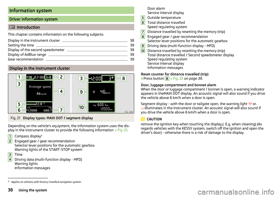
Depending on the vehicle's equipment, the information system uses the dis- play in the instrument cluster to provide the following information » Fig. 21.
Compass display 1)
Engaged gear / gear recommendation
Selector lever positions for the automatic gearbox
Warning lights of the START-STOP system
Time
Driving data (multi-function display - MFD)
Warning lights
Information messages
1234Door alarm
Service interval display
Outside temperature
Total distance travelled
Speed regulating system
Distance travelled by resetting the memory (trip)
Engaged gear / gear recommendation
Selector lever positions for the automatic gearbox
Driving data (multi-function display - MFD)
Distance travelled by resetting the memory (trip)
Total distance travelled / Second speedometer display
Speed regulating system
Service interval display
Information messages
Reset counter for distance travelled (trip)›
Press button
B
» Fig. 22 on page 39 .
Door, luggage compartment and bonnet alarm
When the door or luggage compartment / bonnet is open, a warning indicator appears in theMAXI DOT display. An acoustic signal will also sound if you drive
the vehicle above 6 km/h when a door is open.
Segment display - with the door or tailgate open, the warning light or.
illuminates in the instrument cluster. An acoustic signal will also sound if
you drive the vehicle above 6 km/h when a door is open.
CAUTION
remove the ignition key when touching the display,(. E.g. when cleaning) (As
regards vehicles with the KESSY system, switch off the ignition and open the
driver's door) - otherwise there is a risk of damage to the display.56789101)
Applies to vehicles with factory-installed navigation system.
38Using the system
Page 41 of 200
Setting the timeFig. 22
Buttons in the instrument clus-
ter
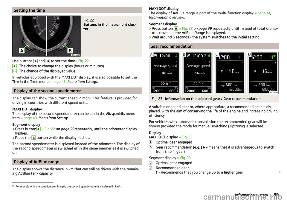
Use buttons
A
and
B
to set the time » Fig. 22.
The choice to change the display (hours or minutes).
The change of the displayed value.
In vehicles equipped with the MAXI DOT display, it is also possible to set the
Time
in the Time menu » page 43, Menu item
Settings
.
Display of the second speedometer
The display can show the current speed in mph 1)
. This feature is provided for
driving in countries with different speed units.
MAXI DOT display
The display of the second speedometer can be set in the
Alt. speed dis.
menu
item » page 43 , Menu item
Settings
.
Segment display
›
Press button
A
» Fig. 22 on page 39 repeatedly, until the odometer display
flashes.
›
Press the
B
button while the display flashes.
The second speedometer is displayed instead of the odometer. The display of the second speedometer is switched offin the same manner as it is switched
on.
Display of AdBlue range
The display shows the distance in km that can still be driven with the remain-
ing AdBlue tank capacity.
ABMAXI DOT display
The display of AdBlue range is part of the multi-function display » page 41,
Information overview .
Segment display›
Press button
A
» Fig. 22 on page 39 repeatedly until instead of total kilome-
tres travelled, the AdBlue Range is displayed.
›
Wait around 5 seconds - the system switches to the initial setting.
Gear recommendation
Fig. 23
Information on the selected gear / Gear recommendation
A suitable engaged gear or, where appropriate, a recommended gear is dis-
played, with the aim of conserving the life of the engine and increasing driving
efficiency.
For vehicles with automatic transmission the recommended gear will be
shown provided the mode for manual switching (Tiptronic) is selected.
Display
MAXI DOT display » Fig. 23
Optimal gear engaged
Gear recommendation (e.g.
means that it is advantageous to switch
from 3. to 4. gear)
Segment display » Fig. 23
Optimal gear engaged
Recommended gear
- Recommends that you change up to a
higher gear
1)
For models with the speedometer in mph, the second speedometer is displayed in km/h.
39Information system
Page 43 of 200
Multifunction display (MFD)
Introduction
This chapter contains information on the following subjects:
Information overview
41
Warning when exceeding the set speed
41
Memory
42
The driving data is displayed in the multifunction display when is ignition is
switched on. After the ignition is switched on, the function that was last selec-
ted before switching off the ignition is displayed.
If vehicles with MAXI DOTdisplay do not show the driving data after switching
on the ignition, select the menu item
MFD
in the main menu and confirm
» page 42 , MAXI DOT display .
On vehicles with a MAXI DOT display, there is an option to fade out the units
and some of the information » page 43, Menu item
Settings
.
Note
If the display of the second speed is activated in mph, the current speed is not
indicated in km/h on the display.
Information overview
Overview of driving data (depending on the vehicle equipment fitted).
Exterior temperature - For vehicles with a MAXI DOT display this information
is always shown.
Driving time - driving time since last clearing the memory.
Current fuel consumption - when the vehicle is stationary or moving slowly,
the fuel consumption is displayed in l/h (in models in some countries the fol-
lowing appears --,- km/l).
Average fuel consumption - is calculated continuously since the last clearing
of the memory. After erasing the memory, no data will appear for the first 300
m driven.
Range - drive distance in km which can be covered with the existing tank ca-
pacity and with the same driving style. If you drive more efficiently this value
can increase.
AdBlue ®
range - drive distance in km which can be covered with the existing
AdBlue ®
tank capacity and with the same driving style. If you drive more effi-
ciently this value can increase.
Distance driven - distance driven since the memory was last cleared.
Average speed - value constantly recalculated, for distance since last clearing
the memory. After erasing the memory, no data will appear for the first 300 m
driven.
Current Speed - digital speedometer.
Oil temperature - if the temperature is lower than 50 °C or if there is a fault in
the system for checking the oil temperature, the
symbols are displayed.
Warning when the preset speed is exceeded - allows the setting of a speed
limit where, if exceeded, an acoustic warning signal and a warning message
appears on the display of the instrument cluster.
Warning when exceeding the set speed
The system offers the possibility to set a speed limit beyond which an acoustic
warning signal will sound and the following warning message (MAXI DOT Dis-
play) and the symbol appears in the display of the instrument cluster.
Adjust the speed limit while the vehicle is stationary
›
Select the menu item
Speed warning
at ( ) or
(
) and confirm.
›
Set the desired speed limit.
›
Confirm the set value, or wait several seconds; your settings will be saved
automatically.
Adjusting the speed limit while the vehicle is moving
›
Select the menu item
Speed warning
at ( ) or
(
) and confirm.
›
Drive at the desired speed.
›
Confirm the current speed as the speed limit.
The set speed limit can be manually adjusted later if needed.
Reset speed limit
›
Select the menu item
Speed warning
at ( ) or
(
) and confirm.
›
By confirming the speed stored in the memory, the speed limit is reset.
The set driving mode remains stored even after switching the ignition on and
off.
41Information system
Page 143 of 200
Operating under different weather conditions
Use only diesel in accordance with the current or expected weather conditions.
Ask the petrol station personnel whether the diesel fuel offered corresponds
to these conditions.
CAUTION
The following instructions must be observed, otherwise there is a risk of dam-
age to the engine and to the exhaust system.■
If a different fuel other than diesel fuel, which complies to the above men-
tioned standards (e.g. petrol) is put into the tank, do not start the engine or
switch on the ignition!
■
The biofuel RME must not be used!
CAUTION
Diesel fuel additives■The diesel fuel in accordance with the prescribed standards meets all the
conditions for a smooth running engine. Therefore, we recommend that you do
not add any fuel additives to the diesel - there is a risk of engine damage or
damage to the exhaust system.
AdBlue ®
And its refilling
Introduction
This chapter contains information on the following subjects:
Check level
141
AdBlue ®
refill
142
In order to reduce pollutant emissions from vehicles with diesel engines and
the SCR catalyst, a urea - AdBlue ®
solution is injected into the exhaust system.
Only use AdBlue ®
that corresponds to the standard ISO 22241-1. Do not add
additives to AdBlue ®
.
The AdBlue ®
consumption is approx. 1.2 l - 1.6 l/1000 km, depending on driving
style, the operating temperature of the system and on the weather conditions.
AdBlue ®
-tank filling level is about 8.5 litres.
WARNINGAdBlue®
can cause skin, eye and respiratory irritation. If your eyes or skin
come into contact with the AdBlue ®
fluid, immediately wash the affected
area for a few minutes with a lot of water. If necessary get medical assis-
tance.
CAUTION
AdBlue ®
attacks the surface of some materials (e.g. as painted parts, plastics,
fabrics). Clean the areas affected with AdBlue ®
using a damp cloth and plenty
of cold water. Remove any dried AdBlue ®
with warm water and a sponge.
Note
■ The AdBlue ®
solution freezes at a temperature of -11 °C and below. The sys-
tem has a heater to ensure the operability at low temperatures.■
We recommend purchasing AdBlue ®
refill bottles from the ŠKODA original
parts.
■
The working life of the AdBlue ®
solution is 4 years. After this time, the solu-
tion must be replaced by a specialist garage.
■
AdBlue ®
is a registered trademark of the VDA. AdBlue ®
is also known as AUS
32 (Aqueous Urea Solution) or DEF (Diesel Exhaust Fluid).
Check level
Read and observe
and on page 141 first.
The filler neck of AdBlue ®
Tank is located in the luggage compartment under
the symbol and the cap marked with the lettering “AdBlue ®
” » Fig. 156 on
page 142 .
The AdBlue ®
level is automatically monitored.
If the available travel distance that can be completed with the remaining AdBl- ue ®
tank capacity drops to about 2400 km, the warning appears on the in-
strument cluster and a request for replenishment of AdBlue ®
appears.
An indication also appears in the instrument cluster showing the maximum
and minimum AdBlue ®
tank capacity.
If the available travel distance that can be driven with the existing AdBlue ®
tank capacity drops down to 0 km, then no motor start is possible.
The distance which can still be driven with the remaining AdBlue ®
, can be de-
termined using the travel data » page 30.
141Inspecting and replenishing
Page 144 of 200
AdBlue®
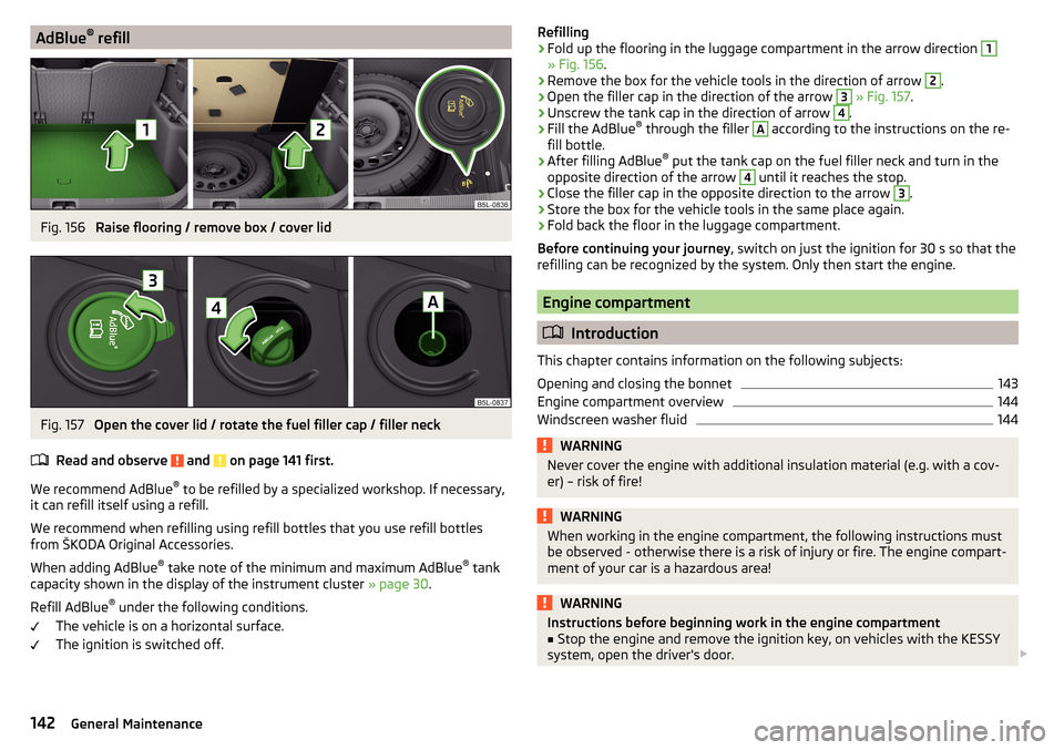
refillFig. 156
Raise flooring / remove box / cover lid
Fig. 157
Open the cover lid / rotate the fuel filler cap / filler neck
Read and observe
and on page 141 first.
We recommend AdBlue ®
to be refilled by a specialized workshop. If necessary,
it can refill itself using a refill.
We recommend when refilling using refill bottles that you use refill bottles
from ŠKODA Original Accessories.
When adding AdBlue ®
take note of the minimum and maximum AdBlue ®
tank
capacity shown in the display of the instrument cluster » page 30.
Refill AdBlue ®
under the following conditions.
The vehicle is on a horizontal surface.
The ignition is switched off.
Refilling›Fold up the flooring in the luggage compartment in the arrow direction 1
» Fig. 156 .
›
Remove the box for the vehicle tools in the direction of arrow
2
.
›
Open the filler cap in the direction of the arrow
3
» Fig. 157 .
›
Unscrew the tank cap in the direction of arrow
4
.
›
Fill the AdBlue ®
through the filler
A
according to the instructions on the re-
fill bottle.
›
After filling AdBlue ®
put the tank cap on the fuel filler neck and turn in the
opposite direction of the arrow
4
until it reaches the stop.
›
Close the filler cap in the opposite direction to the arrow
3
.
›
Store the box for the vehicle tools in the same place again.
›
Fold back the floor in the luggage compartment.
Before continuing your journey , switch on just the ignition for 30 s so that the
refilling can be recognized by the system. Only then start the engine.
Engine compartment
Introduction
This chapter contains information on the following subjects:
Opening and closing the bonnet
143
Engine compartment overview
144
Windscreen washer fluid
144WARNINGNever cover the engine with additional insulation material (e.g. with a cov-
er) – risk of fire!WARNINGWhen working in the engine compartment, the following instructions must
be observed - otherwise there is a risk of injury or fire. The engine compart-
ment of your car is a hazardous area!WARNINGInstructions before beginning work in the engine compartment■Stop the engine and remove the ignition key, on vehicles with the KESSY
system, open the driver's door. 142General Maintenance
Page 171 of 200

No.Consumer27Panoramic tilt / slide sunroof, electric operation of sun blinds28Fuel pump, injectors, AdBlue®
heating29Electric windows - front, outside mirror - Heating, fold-in function,
Adjusting the mirror surface3012 volt power outlet - front and rear31Headlight cleaning system32Heated front seats33Heating, air conditioning, Climatronic, remote control for auxiliary
heating34Car alarm, reserve horn35Automatic gearbox36Tow hitch
Fuses in the engine compartment
Fig. 195
Distribution board cover.
Read and observe and on page 167 first.
With some equipment, the battery cover must be opened before removing the
cover for the fuse box » page 148.
Replacing fuses
›
Turn the securing bracket
A
» Fig. 195 in direction of the arrow. The symbol
is displayed behind the catches. .
›
Remove the cover.
›
Replace the appropriate fuse.
›
Replace the cover on the fuse box and the safety clip
A
move against the
arrow. The symbol is displayed behind the catches .
CAUTIONThe cover of the fuse box in the engine compartment must always be used
correctly, otherwise water may penetrate into the fuse box – there is a risk of
damage to the vehicle!
Fuse arrangement in the engine compartment
Fig. 196
Fuses
Read and observe and on page 167 first.
No.Consumer1Not assigned2Automatic gearbox, AdBlue control system3Battery data module4ABS5Automatic gearbox6Not assigned7Power supply for terminal 15, starter8Radio, instrument cluster, telephone9Not assigned10Engine control system11Aux. heating and ventilation12Databus13Engine control system14Ignition15Lambda probe, fuel pump, glow plug system16Right headlight, right taillight17Horn 169Fuses and light bulbs