emergency towing SKODA YETI 2017 Owner´s Manual
[x] Cancel search | Manufacturer: SKODA, Model Year: 2017, Model line: YETI, Model: SKODA YETI 2017Pages: 200, PDF Size: 28.93 MB
Page 5 of 200
Brake fluid147Vehicle battery147
Wheels
150
Wheels and tyres
150
Operating in winter conditions
152
Do-it-yourself
Emergency equipment and self-help
154
Emergency equipment
154
Changing a wheel
155
Breakdown kit
159
Jump-starting
161
Towing the vehicle
162
Remote control and removable light -
replacing the battery/batteries
164
Emergency unlocking / unlocking of doors
165
Replacing windscreen wiper blades
166
Fuses and light bulbs
167
Fuses
167
Bulbs
170
Technical data
Technical data
175
Basic vehicle data
175
Vehicle-specific data depending on the
engine
181
Index
3Table of Contents
Page 52 of 200

SafeLockRead and observe
and on page 48 first.
SafeLock prevents opening the doors from inside as well as window operation.
This makes an attempted break-in to the vehicle more difficult.
Activating
SafeLock is activated when the vehicle is locked from the outside.
This function is pointed out by the following message on the display of the in-
strument cluster after the ignition is switched off.
Check SAFELOCK! Log book!CHECK DEADLOCK
Activation display
When SafeLock is activated, the warning light in the driver's door flashes for 2
seconds in rapid succession, then starts to flash at longer intervals.
Deactivating
▶ By locking twice within 2 seconds.
▶ or: by deactivating the interior monitor and the towing protection
» page 52 .
The warning light in the driver door flashes rapidly for about 2 seconds, then
goes out and starts to flash at longer intervals after about 30 seconds.
If the vehicle is locked and the safe securing system is switched off, the door
can be opened separately from the inside by a single pull on opening lever.
The Safelock system switches back on when the vehicle is locked.
WARNINGIf the car is locked and the safe securing system activated, no people must
remain in the car as it will then not be possible to either unlock a door or
open a window from the inside. The locked doors make it more difficult for
rescuers to get into the vehicle in an emergency – risk to life!
Individual settings
Read and observe
and on page 48 first.
The following central locking functions can be individually set via the MAXI
DOT display » page 43, Menu item
Settings
.
All doors
The function allows you to unlock all doors, the boot lid and the fuel filler flap.
Single door
The function allows you to unlock only the driver's door and the fuel filler flap
with the radio remote control. KESSY allows the unlocking of a single door
which is in the vicinity of the key, as well as the fuel filler flap. The other doors
and the boot lid are only unlocked once the door handle is unlocked or
touched.
Doors on a vehicle side
This function enables you to unlock both doors on the driver's side and the
fuel filler flap with the radio remote control unit. KESSY allows the unlocking of
both doors which are in the vicinity of the key, as well as the fuel filler flap. The
other doors and the boot lid are only unlocked once the door handle is un-
locked or touched.
Automatic locking/unlocking
This function enables the locking of all doors and the boot lid from a speed of
15 km / h. Opening the doors and the boot lid from the outside is not possible.
The renewed unlocking of the doors and the boot lid is carried out when the
ignition key is removed or when the door is opened from inside (depending on
the individual setting for the central locking system).
Opening/closing a door
Fig. 33
Door handle/door opening lever:
Read and observe
and on page 48 first.
›
To open from the outside , unlock the vehicle and pull the door handle
A
in
the direction of arrow » Fig. 33.
50Using the system
Page 53 of 200
›To
open from the inside pull the door opening lever B and push the door
away from you.›
To the lock from the inside , grab the handle
C
and close the door.
WARNING■
The door must be closed properly, otherwise it could open whilst the ve-
hicle is in motion - There is a risk of death!■
Only open and close the door when there is no one in the opening/closing
range – There is a risk of injury!
■
Never drive with the doors open - it can be fatal!
■
An opened door can close automatically if there is a strong wind or the
vehicle is on an incline – risk of injury!
Child safety lock
Fig. 34
Rear door: Switching the child safety system on/off
Read and observe
and on page 48 first.
The child safety lock prevents the rear door from being opened from the in-
side. The door can only be opened from the outside.
›
To turn on the child safety lock, turn the vehicle key to position
» Fig. 34 .
›
To turn off the child safety lock, turn the vehicle key to position
.
Malfunctions
Read and observe
and on page 48 first.
Synchronise remote
If the buttons on the remote control key have been depressed several times
beyond the effective range of the equipment, or the battery has been replaced
in the remote control key and the vehicle cannot be unlocked with the remote
control, the key must be synchronised.
›
Press any button on the remote control key.
›
Unlock the door with the key in the lock cylinder within 1 minute of pressing the button.
Central locking fault
If the warning light in the driver's door initially flashes quickly for around 2 sec-
onds, and then illuminates for 30 seconds without interruption before flashing
again slowly, you will need to seek the assistance of a specialist garage.
In the case of a fault with the central locking system, the vehicle doors and the
boot lid can be emergency locked or emergency released » page 165.
Failure of the KESSY system
If there is a fault in the KESSY system, the appropriate error message is dis-
played in the instrument cluster.
Low voltage of the key battery
If the voltage of the key battery is too low, a message appears in the display of
the instrument cluster referring to the need to replace the battery. Replace
the battery » page 164.
Anti-theft alarm system
Introduction
This chapter contains information on the following subjects:
Alarm trigger
52
Interior monitor and towing protection
52
The alarm system triggers audible and visual signals if an attempt is made to
break into the vehicle (hereafter referred to as alarm).
The alarm system is activated automatically approximately 30 seconds after the vehicle is locked. This is automatically disabled after release.
51Unlocking and opening
Page 62 of 200
Automatic driving light controlFig. 44
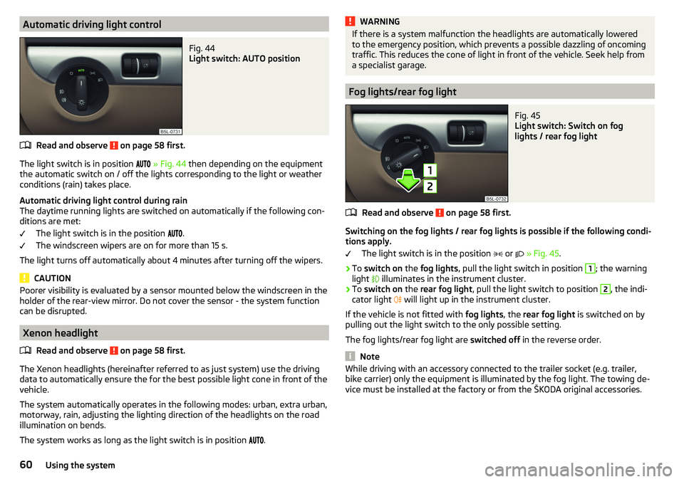
Light switch: AUTO position
Read and observe on page 58 first.
The light switch is in position
» Fig. 44 then depending on the equipment
the automatic switch on / off the lights corresponding to the light or weather
conditions (rain) takes place.
Automatic driving light control during rain
The daytime running lights are switched on automatically if the following con-
ditions are met:
The light switch is in the position .
The windscreen wipers are on for more than 15 s.
The light turns off automatically about 4 minutes after turning off the wipers.
CAUTION
Poorer visibility is evaluated by a sensor mounted below the windscreen in the
holder of the rear-view mirror. Do not cover the sensor - the system function
can be disrupted.
Xenon headlight
Read and observe
on page 58 first.
The Xenon headlights (hereinafter referred to as just system) use the drivingdata to automatically ensure the for the best possible light cone in front of the
vehicle.
The system automatically operates in the following modes: urban, extra urban,
motorway, rain, adjusting the lighting direction of the headlights on the road
illumination on bends.
The system works as long as the light switch is in position
.
WARNINGIf there is a system malfunction the headlights are automatically lowered
to the emergency position, which prevents a possible dazzling of oncoming
traffic. This reduces the cone of light in front of the vehicle. Seek help from
a specialist garage.
Fog lights/rear fog light
Fig. 45
Light switch: Switch on fog
lights / rear fog light
Read and observe on page 58 first.
Switching on the fog lights / rear fog lights is possible if the following condi-
tions apply.
The light switch is in the position
or
» Fig. 45 .
›
To switch on the fog lights , pull the light switch in position
1
; the warning
light
illuminates in the instrument cluster.
›
To switch on the rear fog light , pull the light switch to position
2
, the indi-
cator light
will light up in the instrument cluster.
If the vehicle is not fitted with fog lights, the rear fog light is switched on by
pulling out the light switch to the only possible setting.
The fog lights/rear fog light are switched off in the reverse order.
Note
While driving with an accessory connected to the trailer socket (e.g. trailer,
bike carrier) only the equipment is illuminated by the fog light. The towing de-
vice must be installed at the factory or from the ŠKODA original accessories.60Using the system
Page 126 of 200

Towing device and trailer
Hitch
Introduction
This chapter contains information on the following subjects:
Description
124
Setting the ready position
125
Check the setting of the standby position
125
Assemble the ball rod
125
Check proper mounting
126
Removing ball rod - Step 1
126
Removing ball rod - Step 2
127
Vertical load with mounted accessories
127
The maximum trailer nose weight when towing a trailer is 80 kg, for vehicles
with four-wheel drive and the 2.0 l / 103 kW TDI CR or 2.0 l / 110 kW TDI CR
engine, it is 85 kg. Other information (e.g. on the nameplate of the trailer de-
vice) provide only about the test values of the device information.
WARNING■ Check that the tow bar is seated correctly and is secured in the mounting
recess before the start of every journey.■
When the ball rod is not used and properly secured in the receiving shaft,
this could be damaged or incomplete and must not be used -There is a risk
of an accident.
■
Do not modify or adapt the towing device in any way.
■
Keep the mounting recess of the towing equipment clean at all times.
Such dirt prevents the ball head from being attached securely.
DescriptionFig. 143
Carrier for the towing device/tow bar
Read and observe
on page 124 first.
The ball rod is detachable and is located in the stowage compartment for the
spare / emergency wheel.
Support for the towing device and tow bar » Fig. 143
13-pin power socket
Mounting recess
Safety eyelet
Cover for the mounting recess
Dust cap
Locking ball
Green marking on the handwheel
Handwheel
Key
Lock cap
Red marking on the handwheel
Green box on the tow bar
Tow ball
12345678910111213124Driving
Page 157 of 200
WARNINGAlways properly secure the fire extinguisher - there is a risk of injury in the
event of sudden braking or a vehicle collision.
Vehicle tool kit
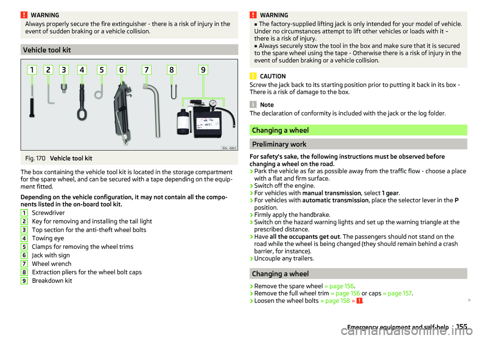
Fig. 170
Vehicle tool kit
The box containing the vehicle tool kit is located in the storage compartment
for the spare wheel, and can be secured with a tape depending on the equip-
ment fitted.
Depending on the vehicle configuration, it may not contain all the compo-
nents listed in the on-board tool kit.
Screwdriver
Key for removing and installing the tail light
Top section for the anti-theft wheel bolts
Towing eye
Clamps for removing the wheel trims
Jack with sign
Wheel wrench
Extraction pliers for the wheel bolt caps
Breakdown kit
123456789WARNING■ The factory-supplied lifting jack is only intended for your model of vehicle.
Under no circumstances attempt to lift other vehicles or loads with it –
there is a risk of injury.■
Always securely stow the tool in the box and make sure that it is secured
to the spare wheel using the tape - Otherwise there is a risk of injury in the
event of sudden braking or a vehicle collision.
CAUTION
Screw the jack back to its starting position prior to putting it back in its box -
There is a risk of damage to the box.
Note
The declaration of conformity is included with the jack or the log folder.
Changing a wheel
Preliminary work
For safety's sake, the following instructions must be observed before
changing a wheel on the road.
›
Park the vehicle as far as possible away from the traffic flow - choose a place
with a flat and firm surface.
›
Switch off the engine.
›
For vehicles with manual transmission , select 1 gear.
›
For vehicles with automatic transmission , place the selector lever in the P
position.
›
Firmly apply the handbrake.
›
Switch on the hazard warning lights and set up the warning triangle at the
prescribed distance.
›
Have all the occupants get out . The passengers should not stand on the
road while the wheel is being changed (they should remain behind a crash
barrier, for instance).
›
Uncouple any trailers.
Changing a wheel
›
Remove the spare wheel » page 156.
›
Remove the full wheel trim » page 156 or caps » page 157 .
›
Loosen the wheel bolts » page 158 » .
155Emergency equipment and self-help
Page 165 of 200
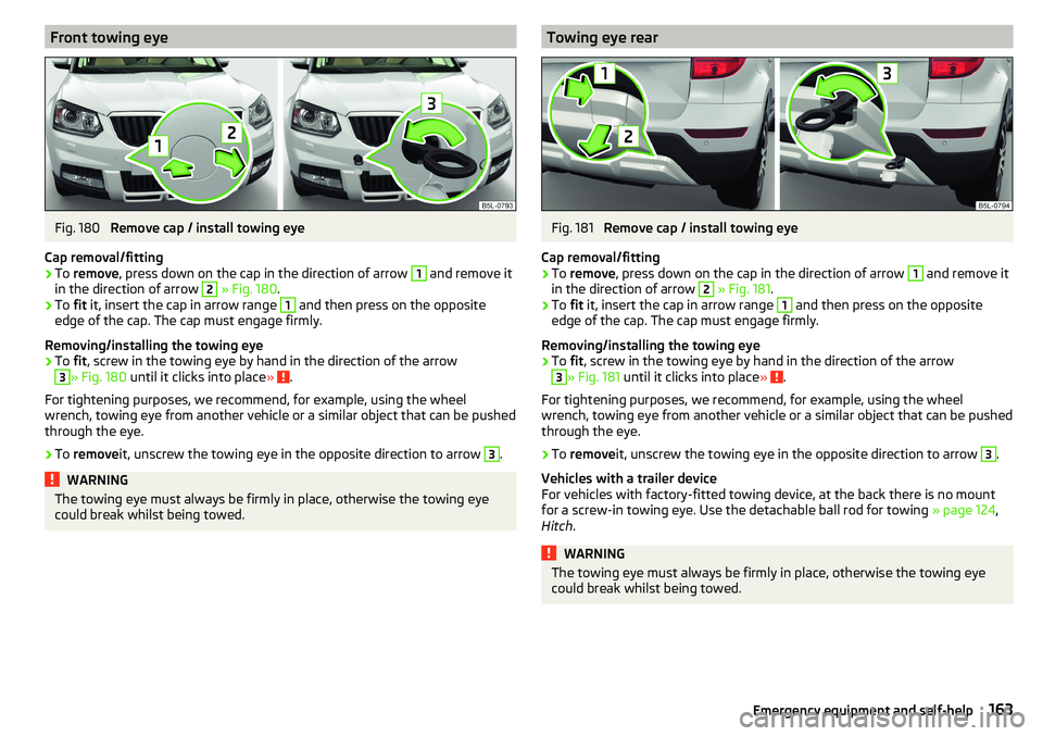
Front towing eyeFig. 180
Remove cap / install towing eye
Cap removal/fitting
›
To remove , press down on the cap in the direction of arrow
1
and remove it
in the direction of arrow
2
» Fig. 180 .
›
To fit it, insert the cap in arrow range
1
and then press on the opposite
edge of the cap. The cap must engage firmly.
Removing/installing the towing eye
›
To fit, screw in the towing eye by hand in the direction of the arrow
3
» Fig. 180 until it clicks into place » .
For tightening purposes, we recommend, for example, using the wheel
wrench, towing eye from another vehicle or a similar object that can be pushed through the eye.
›
To remove it, unscrew the towing eye in the opposite direction to arrow
3
.
WARNINGThe towing eye must always be firmly in place, otherwise the towing eye
could break whilst being towed.Towing eye rearFig. 181
Remove cap / install towing eye
Cap removal/fitting
›
To remove , press down on the cap in the direction of arrow
1
and remove it
in the direction of arrow
2
» Fig. 181 .
›
To fit it, insert the cap in arrow range
1
and then press on the opposite
edge of the cap. The cap must engage firmly.
Removing/installing the towing eye
›
To fit, screw in the towing eye by hand in the direction of the arrow
3
» Fig. 181 until it clicks into place » .
For tightening purposes, we recommend, for example, using the wheel
wrench, towing eye from another vehicle or a similar object that can be pushed
through the eye.
›
To remove it, unscrew the towing eye in the opposite direction to arrow
3
.
Vehicles with a trailer device
For vehicles with factory-fitted towing device, at the back there is no mount
for a screw-in towing eye. Use the detachable ball rod for towing » page 124,
Hitch .
WARNINGThe towing eye must always be firmly in place, otherwise the towing eye
could break whilst being towed.163Emergency equipment and self-help
Page 170 of 200

Fuses in the dashboardFig. 193
Distribution board cover.
Read and observe and on page 167 first.
The fuses are located on the left side of the dash panel behind a cover.
Replacing fuses
›
Remove the ignition key, turn off the lights and all electrical consumers.
›
Insert a screwdriver into the opening in the cover in the direction of the ar-
row » Fig. 193 .
›
Remove the cover of the fuse box and remove.
›
Remove the plastic clip from the holder in the fuse box cover in the dash
panel.
›
Use the clip to pull the fuse out, then insert a new fuse.
›
Re-insert the cover of the fuse box .
›
Replace the bracket at the original position.
Fuse arrangement in the dashboard
Fig. 194
Fuses
Read and observe and on page 167 first.No.Consumer1Heating of the gearbox vent (diesel engine)
Automatic gearbox2Towing hitch - left light3Trailer device - electrical outlet4Instrument cluster control lever under the steering wheel, camera5Air blower for heating, radiator fan, air conditioning system, Clima-
tronic6Rear window wiper7emergency call8Towing hitch - right light9Interior lighting, rear fog light10Rain sensor, light switch, diagnostic socket11Left side front headlight12Right side front headlight13Radio14Central control system, engine management system15Light switch16All-wheel drive17KESSY, steering lock18Diagnostic connector, engine control system, brake sensor, four-
wheel drive, START-STOP19ABS, ESP, switch for tyre air pressure control, parking aid, switch for
OFF ROAD mode, START STOP button20Airbag21Variable Service Interval - WIV, reversing lamps, dimmable mirrors,
pressure sensor, telephone preparation, air mass meter, headlamp
levelling and swivelling headlights22Instrument cluster, electromechanical power steering, databus23Central locking, boot lid24Electric windows - Rear25Rear window heater, auxiliary heating and ventilation26Power socket in the boot 168Do-it-yourself
Page 188 of 200
DoorChild safety lock51
Emergency locking165
Emergency locking of the driver's door165
Opening/Closing50
warning light door open32
Door alarm38
Door open warning light
32
Drive Driving through water
109
Driver Steering Recommendation (DSR)111
Driving Emissions
177
Fuel consumption177
through water109
Top speed181
DSR111
E
Economical driving
108
EDL111
Electrical power windows55
Button in the rear doors54
Electric power windows53
Electric window Buttons in the driver´s door
54
Electric windows Operational faults
55
Electronic Differential Lock (EDL)111
Electronic immobiliser100
Emergency Hazard warning light system
61
Jump-starting161
Selector lever-unlocking166
Starting / stopping the engine with the push of a button
101
Starting the engine / stopping with the push of a button
102
Towing the vehicle162
Towing the vehicle using the trailer device163
Tyre repair159
Unlocking/locking the door165
Unlocking / locking the door165
Emergency equipment Fire extinguisher
154
First aid kit154
Jack155
Reflective vest154
Vehicle tool kit155
Warning triangle154
Emission control system35
Emissions177
Engine Running in
108
Engine compartment142
Brake fluid147
Coolant146
Engine oil144
Overview144
Vehicle battery147
Windscreen washer fluid144
Engine drag torque control (MSR)110
Engine number175
engine oil specification
145
Engine oil144
Check145
Oil changing144
Refilling145
Warning light33
EPC35
ESC Operation
110
Warning light34
Extended warranty5
Exterior temperature41
F
Fastening elements
87
Fatigue detection122
Films136
Fire extinguisher154
First aid kit154
Flashing59
Flexible storage compartment88
Floor covering in the luggage compartment88
Fog lights Warning light
37
Fog lights/rear fog light60
Fog lights with the CORNER function61
folding table on the rear seat backrest
84
Folding table on the front seat backrest
83
Footmats106
see footmats106
Force limiter Sliding/tilting roof
56
Window55
Front seats68
Fuel139
Diesel140
Fuel gauge29
refer to Fuel139
Refuelling139
Unleaded petrol140
Warning light36
Fuel consumption177
Fuel filter information messages
30
Fuel reserve36
Fuses167
in the dashboard168
in the engine compartment169
186Index
Page 189 of 200
G
Gear change Gear recommendation
39
Information on the selected gear39
Gear changing Gear stick
105
Genuine parts132
Glasses compartment81
GPS See Owner's Manual Infotainment
6
gradeability179
H
Handbrake
104
Warning light32
Hazard warning light system61
HBA111
Headrests73
Heating93
Air distribution control96
Controls94
Mirrors67
Seats74
Windscreen and rear window63
Help in an emergency8
HHC111
Hill Start Assist (HHC)111
Hitch124
Horn27
I
Ignition lock
101
Images See Owner's Manual Infotainment
6
Immobiliser100
In an emergency Changing a wheel
155
incline179
Inertia reel15
Information about the towing process162
Information system38
Door alarm38
Gear recommendation39
MAXI DOT display42
Multifunction display41
Service interval display44
Infotainment6
Instrument cluster28
Auto Check Control30
Display of the second speedometer39
see instrument cluster28
Warning lights31
instrument lighting29
interior light62
Interior lighting63
Interior monitor52
iPad holder84
ISOFIX24
J
Jack
155
- fit158
Jump-starting161
K
KESSY Unlocking/locking
49
key Switch on/off ignition
101
Key Changing battery
164
Lock48
Starting / stopping the engine101
Unlock48
L
Lamp failure Warning light
34
Lamps Warning light
34
LEAVING HOME61
lever Turn signal/main beam
59
Lever Cruise control
122
Operation of the information system40
Windscreen wipers65
light Flash
59
instruments29
Light Automatic driving light control
60
COMING HOME / LEAVING HOME61
Driving abroad62
Fog lights/rear fog light60
Fog lights with the CORNER function61
Headlight cleaning system66
Replacing bulbs170
Turn signal/main beam59
Xenon headlight60
lighting Luggage Storage
90
Lighting Interior lighting
62
Lights58
Cockpit62
Daylight running59
Dipped beam58
Hazard warning light system61
Headlight range control58
Parking lights58, 61
Switching on and off58
Warning lights31
Load176
187Index