stop start SMART FORTWO COUPE 2010 User Guide
[x] Cancel search | Manufacturer: SMART, Model Year: 2010, Model line: FORTWO COUPE, Model: SMART FORTWO COUPE 2010Pages: 216, PDF Size: 9.7 MB
Page 85 of 216
XBriefly pull the gear selector lever
backward in the - direction ( Y page 79).
or
XPull left shift paddle 0046 (Y page 82)
towards you.
The transmission shifts to the next lower
gear.
Kickdown
You can use kickdown when you want
maximum acceleration.
XPress the accelerator pedal past the
point of resistance.
Depending on the engine speed the
transmission shifts into a lower gear.XWhen you have reached the desired speed,
briefly push the gear selector lever
forward in the + direction ( Y page 79).
or
XPull right shift paddle 008A (Y page 82)
towards you.
The transmission shifts to the next
higher gear.
Deactivating manual gearshifting
XWith drive position D selected: Pull and
hold right shift paddle 008A (Y page 82)
towards you for longer than two seconds.
or
XWith manual gearshifting M selected:
Move the gear selector lever to drive
position D ( Y page 79).
System-controlled automatic
gearshifting is switched on again.
Emergency operation (limp-home
mode)
In this mode only a certain gear or a
certain gear combination can be selected.
This mode is triggered in case of
transmission malfunctions and enables you
driving to the nearest workshop such as a
smart center.
If vehicle acceleration becomes less
responsive or sluggish or the transmission
no longer shifts, the transmission is most
likely operating in limp-home (emergency
operation) mode. The transmission
position indicator flashes and the ¬
symbol appears in the multifunction
display.
Driving in limp-home mode:XMove the gear selector lever to drive
position D ( Y page 79).XContinue to drive.XHave the transmission checked at an
authorized smart center as soon as
possible.
i It is possible that a gear combination
including the reverse gear can not be
selected. Keep in mind when parking,
that reversing the vehicle might be
impossible.
In case of a minor transmission
malfunction, it might be possible to teach-
in the transmission in order to restore the
normal transmission mode.
i If the attempt to teach-in the
transmission fails, you cannot continue
to drive. Therefore we strongly
recommend that you have the
transmission taught-in at a qualified
workshop or at an authorized smart
center.
Teaching-in the transmission system:
XStop the vehicle in a safe location.XMove the gear selector lever to park
position P.XTurn off the engine.XWait at least 30 seconds before
restarting.XPress the brake pedal.Transmission83>> Controls.451_AKB; 3; 22, en-USd2ureepe,Version: 2.11.8.12009-07-27T09:36:34+02:00 - Seite 83Z
Page 87 of 216
Multifunction display illumination
The multifunction display illumination
comes on when the starter switch is in
position 1. It goes out after approximately
30 seconds when the starter switch is in
position 0.
For adjusting the multifunction display
illumination, see “Adjusting instrument
cluster illumination” ( Y page 89).
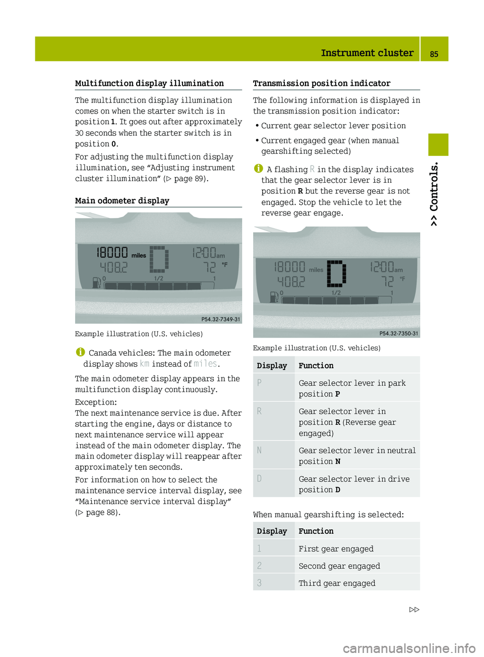
Main odometer display
Example illustration (U.S. vehicles)
i Canada vehicles: The main odometer
display shows km instead of miles.
The main odometer display appears in the
multifunction display continuously.
Exception:
The next maintenance service is due. After
starting the engine, days or distance to
next maintenance service will appear
instead of the main odometer display. The
main odometer display will reappear after
approximately ten seconds.
For information on how to select the
maintenance service interval display, see
“Maintenance service interval display”
( Y page 88).
Transmission position indicator
The following information is displayed in
the transmission position indicator:
R Current gear selector lever position
R Current engaged gear (when manual
gearshifting selected)
i A flashing R in the display indicates
that the gear selector lever is in
position R but the reverse gear is not
engaged. Stop the vehicle to let the
reverse gear engage.
Example illustration (U.S. vehicles)
DisplayFunctionPGear selector lever in park
position PRGear selector lever in
position R (Reverse gear
engaged)NGear selector lever in neutral
position NDGear selector lever in drive
position D
When manual gearshifting is selected:
DisplayFunction1First gear engaged2Second gear engaged3Third gear engagedInstrument cluster85>> Controls.451_AKB; 3; 22, en-USd2ureepe,Version: 2.11.8.12009-07-27T09:36:34+02:00 - Seite 85Z
Page 88 of 216
DisplayFunction4Fourth gear engaged5Fifth gear engaged
Digital clock
Example illustration (U.S. vehicles)
i Canada vehicles: The digital clock
shows a 24 h-clock instead of a
12 h-clock.
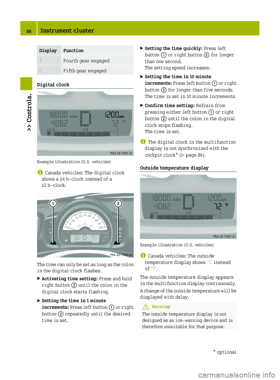
The time can only be set as long as the colon
in the digital clock flashes.
XActivating time setting: Press and hold
right button 0047 until the colon in the
digital clock starts flashing.XSetting the time in 1 minute
increments: Press left button 0046 or right
button 0047 repeatedly until the desired
time is set.XSetting the time quickly: Press left
button 0046 or right button 0047 for longer
than one second.
The setting speed increases.XSetting the time in 10 minute
increments: Press left button 0046 or right
button 0047 for longer than five seconds.
The time is set in 10 minute increments.XConfirm time setting: Refrain from
pressing either left button 0046 or right
button 0047 until the colon in the digital
clock stops flashing.
The time is set.
i The digital clock in the multifunction
display is not synchronized with the
cockpit clock* ( Y page 89).
Outside temperature display
Example illustration (U.S. vehicles)
i Canada vehicles: The outside
temperature display shows °C instead
of °F.
The outside temperature display appears
in the multifunction display continuously.
A change of the outside temperature will be
displayed with delay.
GWarning!
The outside temperature display is not
designed as an ice-warning device and is
therefore unsuitable for that purpose.
86Instrument cluster>> Controls.* optional451_AKB; 3; 22, en-USd2ureepe,Version: 2.11.8.12009-07-27T09:36:34+02:00 - Seite 86
Page 89 of 216

Indicated temperatures just above the
freezing point do not guarantee that the
road surface is free of ice. The road may
still be icy, especially in wooded areas or
on bridges. Your vehicle could start to skid
if you do not adjust your driving style
accordingly.
Therefore, always adjust your driving style
to the prevailing road and weather
conditions.
Freeze warning (Canada vehicles only)
When the outside temperature falls below
3 ¥ , the multifunction display makes you
aware of the fact that the road may be icy.
An additional freeze warning, i.e. an ice
crystal symbol, in the multifunction
display flashes. After 60 seconds, the
freeze warning stops flashing but
continues to be displayed. When the
outside temperature rises above 3 ¥, the
freeze warning goes out.
Fuel level display
Example illustration (U.S. vehicles)
The fuel level display shows the tank’s fuel
level with the aid of eight segments. The
number of dark segments indicates the fuel
level in the tank. If all eight segments are
dark, the tank is full.
You are driving on reserve fuel if there are
no more than 1.0 US gal (3.78 l) of fuel in the
tank.
If this occurs,
R the fuel pump symbol in the fuel level
display flashes
R the reserve fuel indicator shows the fuel
level in the tank in 0.1 US gal (0.5 l)
increments
For selecting the reserve fuel indicator to
be displayed in the status indicator, see
“Reserve fuel indicator” ( Y page 88).
Selecting display for status indicator
You can select the information to be
displayed in the status indicator:
R Trip odometer display ( Y page 88)
R Maintenance service interval display
( Y page 88)
R Reserve fuel indicator ( Y page 88)
0046Selecting display for status indicator,
setting the clock, activating
maintenance service interval display0047Setting the clock, adjusting instrument
cluster illuminationInstrument cluster87>> Controls.451_AKB; 3; 22, en-USd2ureepe,Version: 2.11.8.12009-07-27T09:36:34+02:00 - Seite 87Z
Page 109 of 216
008AFuel filler cap0088Fuel type label0086HolderXTurn off the engine.XRemove the key from the starter switch.XOpen the fuel filler flap by pulling at the
point indicated by arrow 0046.XTurn fuel filler cap 008A counterclockwise
and hold on to it until possible pressure
is released.XTake off fuel filler cap 008A.
!
The fuel filler cap is tethered to the
fuel filler flap. Do not drop the fuel
filler cap. It could damage the vehicle
paint finish.
XInsert fuel filler cap 008A in direction of
arrow 0047 into holder 0086 on the inside of
the fuel filler flap.XFully insert filler nozzle unit and
refuel.XOnly fill your tank until the filler nozzle
unit cuts out — do not top off or overfill .GWarning!
Overfilling of the fuel tank may create
pressure in the system which could cause a
gas discharge. This could cause the gas to
spray back out when removing the fuel pump
nozzle, which could cause personal injury.
XReplace fuel filler cap 008A.XTurn fuel filler cap 008A clockwise until
the handle grip overturns.
i Make sure to close the fuel filler flap
before locking the vehicle as the fuel
filler flap locking pin prevents closing
after you have locked the vehicle.
XClose the fuel filler flap.
You should hear the latch close shut.
i Only use premium unleaded gasoline
with a minimum Posted Octane Rating of
91 (average of 96 RON/86 MON).
Information on gasoline quality can
normally be found on the fuel pump.
Please contact gas station personnel in
case labels on the pump cannot be found.
For more information on gasoline, see
“Premium unleaded gasoline”
( Y page 207) and “Fuel requirements”
( Y page 208), or contact an authorized
smart center.
Check regularly and before a long trip
For information on quantities and
requirements of operating agents, see
“Service fluids and capacities”
( Y page 204).
Check the following:
R Engine oil level ( Y page 108)
R Tire inflation pressure ( Y page 116)
R Coolant level ( Y page 111)
R Vehicle lighting ( Y page 164)
R Windshield washer system ( Y page 112)
R Brake fluid ( Y page 113)
Engine compartment
Engine compartment cover
Open the engine compartment cover to
check the engine oil level and if necessary,
to add engine oil.
GWarning!
High outside temperature, stop-and-go
traffic, driving on long uphill grades or
driving at high engine speed may increase
the temperature in the engine
compartment. Therefore, the engine
compartment cover and parts in the area
around the engine compartment cover may
be hot. Parts of the engine can become very
hot. To prevent burns, let the engine cool
off completely before touching the engine
Engine compartment107>> Operation.451_AKB; 3; 22, en-USd2ureepe,Version: 2.11.8.12009-07-27T09:36:34+02:00 - Seite 107Z
Page 120 of 216
placard. If your vehicle has tires of a
different size than the size indicated on
the Tire and Loading Information placard,
you should determine the proper tire
inflation pressure for those tires.
As an added safety feature, your vehicle has
been equipped with a tire pressure
monitoring system (TPMS) that illuminates
a low tire pressure telltale when one or
more of your tires is significantly
underinflated.
Accordingly, when the low tire pressure
telltale illuminates, you should stop and
check your tires as soon as possible, and
inflate them to the proper pressure.
Driving on a significantly underinflated
tire causes the tire to overheat and can lead
to tire failure.
Underinflation also reduces fuel
efficiency and tire tread life, and may
affect the vehicle’s handling and stopping
ability. Please note that the TPMS is not a
substitute for proper tire maintenance,
and it is the driver’s responsibility to
maintain correct tire pressure, even if
underinflation has not reached the level to
trigger illumination of the TPMS low tire
pressure telltale.
Your vehicle has also been equipped with a
TPMS malfunction indicator to indicate
when the system is not operating properly.
The TPMS malfunction indicator is
combined with the low tire pressure
telltale. When the system detects a
malfunction, the telltale will flash for
approximately 1 minute and then remain
continuously illuminated.
This sequence will continue upon
subsequent vehicle start-ups as long as the
malfunction exists. When the malfunction
indicator is illuminated, the system may
not be able to detect or signal low tire
pressure as intended.
TPMS malfunctions may occur for a variety
of reasons, including the installation of
incompatible replacement or alternatetires or wheels on the vehicle that prevent
the TPMS from functioning properly. Always
check the TPMS malfunction telltale after
replacing one or more tires or wheels on
your vehicle to ensure that the replacement
or alternate tires and wheels allow the
TPMS to continue to function properly.
i If a condition causing the TPMS to
malfunction develops, it may take up to
10 minutes for the system to signal a
malfunction using the TPMS telltale
flashing and illumination sequence.
The telltale extinguishes after a few
minutes driving if the malfunction has
been corrected.
i Operating radio transmission
equipment (e.g. wireless headsets, two-
way radios) in or near the vehicle could
cause the TPMS to malfunction.
i USA only:
This device complies with Part 15 of the
FCC Rules. Operation is subject to the
following two conditions:
1. This device may not cause harmful interference, and
2. this device must accept any interference received, including
interference that may cause
undesired operation.
Any unauthorized modification to this
device could void the user’s authority to
operate the equipment.
i Canada only:
This device complies with RSS‑210 of
Industry Canada. Operation is subject to
the following two conditions:
1. This device may not cause interference, and
2. this device must accept any interference received, including118Tires and wheels>> Operation.
451_AKB; 3; 22, en-USd2ureepe,Version: 2.11.8.12009-07-27T09:36:34+02:00 - Seite 118
Page 121 of 216
interference that may cause
undesired operation of the device.
Any unauthorized modification to this
device could void the user’s authority to
operate the equipment.
Restarting the TPMSGWarning!
It is the driver’s responsibility to
calibrate the TPMS on the recommended
cold inflation pressure. Underinflated
tires affect the ability to steer or brake
and might cause you to lose control of the
vehicle.
When you restart the TPMS, the system sets
new reference values for each tire.
The TPMS must be restarted when you have
adjusted the tire inflation pressure to a
new level (e.g. because of different load or
driving conditions). The TPMS is then
recalibrated to the current tire inflation
pressures.
XUsing the Tire and Loading Information
placard on the driver’s door B‑pillar
( Y page 120), make sure the tire
inflation pressure of all four tires is
correct.
i Restart the TPMS after adjusting the
tire inflation pressure to the inflation
pressure recommended for the vehicle
operating condition. Tire pressure
should only be adjusted on cold tires.
Observe the recommended tire inflation
pressure on the Tire and Loading
Information placard on the driver’s door
B‑pillar ( Y page 120).
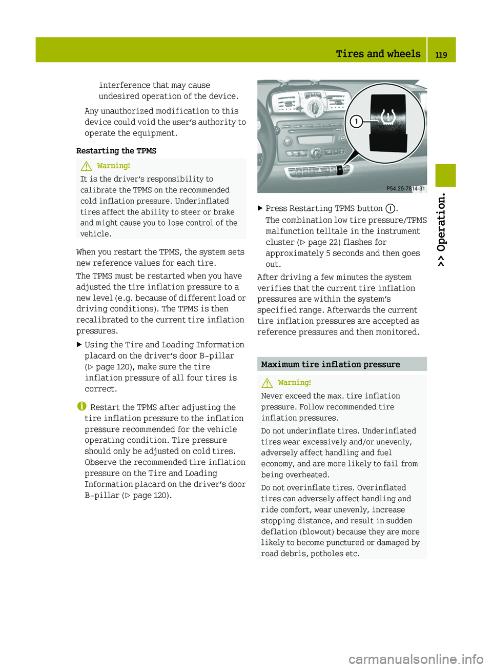
XPress Restarting TPMS button 0046.
The combination low tire pressure/TPMS
malfunction telltale in the instrument
cluster ( Y page 22) flashes for
approximately 5 seconds and then goes
out.
After driving a few minutes the system
verifies that the current tire inflation
pressures are within the system’s
specified range. Afterwards the current
tire inflation pressures are accepted as
reference pressures and then monitored.
Maximum tire inflation pressure
GWarning!
Never exceed the max. tire inflation
pressure. Follow recommended tire
inflation pressures.
Do not underinflate tires. Underinflated
tires wear excessively and/or unevenly,
adversely affect handling and fuel
economy, and are more likely to fail from
being overheated.
Do not overinflate tires. Overinflated
tires can adversely affect handling and
ride comfort, wear unevenly, increase
stopping distance, and result in sudden
deflation (blowout) because they are more
likely to become punctured or damaged by
road debris, potholes etc.
Tires and wheels119>> Operation.451_AKB; 3; 22, en-USd2ureepe,Version: 2.11.8.12009-07-27T09:36:34+02:00 - Seite 119Z
Page 138 of 216
GWarning!
If other than recommended brake pads are
installed, or other than recommended brake
fluid is used, the braking properties of the
vehicle can be degraded to an extent that
safe braking is substantially impaired.
This could result in an accident.
GWarning!
New brake pads will not achieve their
optimal braking effect until after several
hundred miles (kilometers). This means
that you must compensate for the reduced
braking effect by pressing harder on the
brake pedal and adapt your driving style
accordingly. The same applies after brake
pads or brake discs have been changed.
Drive sensibly - save fuel
Fuel consumption, to a great extent,
depends on driving habits and operating
conditions.
To save fuel you should:
R Shift gears in a timely manner.
R Avoid frequent acceleration and
deceleration.
R Keep tires at the recommended inflation
pressures.
R Remove carriers* when not in use.
R Remove unnecessary loads.
R Allow engine to warm up under low load
use.
R Have all maintenance work performed at
the intervals specified in the
Maintenance Booklet and as required by
the Maintenance System. Contact an
authorized smart center.
Fuel consumption is also increased by
driving in cold weather, in stop-and-go
traffic, on short trips, and in hilly areas.
Catalytic converter
Your smart is equipped with monolithic-
type catalytic converter, an important
element in conjunction with the oxygen
sensors to achieve substantial control of
the pollutants in the exhaust emissions.
Keep your vehicle in proper operating
condition by following our recommended
maintenance instructions as outlined in
your Maintenance Booklet.GWarning!
The catalytic converter can become very
hot. Coming into contact with the catalytic
converter could result in burns.
Note the following:
R Do not remove the protective heat guards.
R Do not apply any underseal.
R As with any vehicle, do not idle, park, or
operate this vehicle in areas where
combustible materials such as grass,
hay, or leaves can come into contact with
the hot exhaust system, as these
materials could be ignited and cause a
vehicle fire.
! To prevent damage to the catalytic
converter, only use premium unleaded
gasoline in this vehicle.
Any noticeable irregularities in engine
operation should be repaired promptly.
Otherwise, excessive unburned fuel may
reach the catalytic converter, causing it
to overheat and potentially start a fire.
It is essential to observe the following
points, as there is otherwise a danger of
overheating and the catalytic converter
may be damaged.
R Fill up only with premium unleaded
gasoline. Even small quantities of
leaded gasoline can damage the catalytic
converter.
R Make sure you adhere to the prescribed
service intervals.
136Driving instructions>> Operation.* optional451_AKB; 3; 22, en-USd2ureepe,Version: 2.11.8.12009-07-27T09:36:34+02:00 - Seite 136
Page 153 of 216

Safety systems ProblemPossible causes/consequences and 0050 Solutions0082The seat belt
telltale
illuminates
constantly for a
maximum of
6 seconds after
starting the
engine.Regardless of whether the seat belt is fastened or not, the seat
belt telltale always comes on and remains lit for 6 seconds
after starting the engine.XFasten your seat belts.0082The seat belt
telltale
illuminates
constantly. An
additional
warning chime
sounds for a
maximum of
6 seconds after
starting the
engine.The driver’s seat belt is unfastened.XFasten your seat belts.0082The seat belt
telltale flashes
with
increasing
frequency of a
warning chime
for a maximum
of 60 seconds.The vehicle speed once exceeds 15 mph (25 km/h), and both the
driver’s and passenger seat belt are unfastened.XFasten your seat belts.
If the driver’s or the passenger seat belt remains unfastened
after 60 seconds, the warning chime stops sounding. The seat
belt telltale stops flashing but continues to be illuminated.
The seat belt telltale will only go out if both the driver’s and
the passenger seat belt (with the passenger seat occupied) are
fastened, or the vehicle is standing still and a door is opened.
0081Scenario 1:
The SRS
indicator lamp
illuminates
when the
ignition is
switched on and
goes out after a
maximum of
4 seconds.The subsequent self check of the safety systems detected no
malfunction. The supplemental restraint system is
operational.What to do if ...151>> Practical hints.451_AKB; 3; 22, en-USd2ureepe,Version: 2.11.8.12009-07-27T09:36:34+02:00 - Seite 151Z
Page 156 of 216
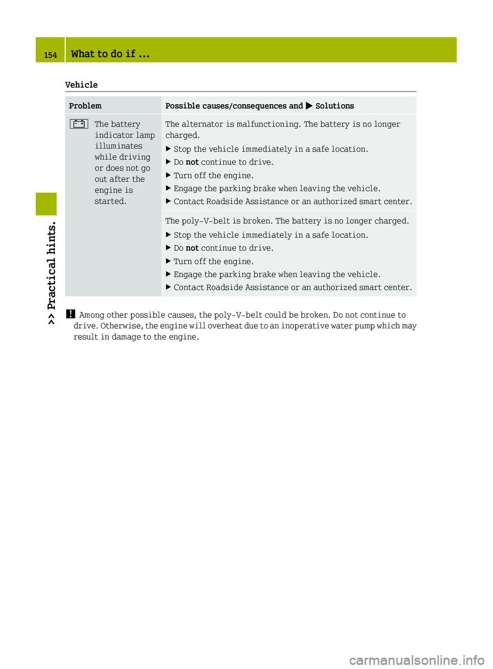
VehicleProblemPossible causes/consequences and 0050 Solutions003FThe battery
indicator lamp
illuminates
while driving
or does not go
out after the
engine is
started.The alternator is malfunctioning. The battery is no longer
charged.XStop the vehicle immediately in a safe location.XDo not continue to drive.XTurn off the engine.XEngage the parking brake when leaving the vehicle.XContact Roadside Assistance or an authorized smart center.The poly-V-belt is broken. The battery is no longer charged.XStop the vehicle immediately in a safe location.XDo not continue to drive.XTurn off the engine.XEngage the parking brake when leaving the vehicle.XContact Roadside Assistance or an authorized smart center.
!
Among other possible causes, the poly-V-belt could be broken. Do not continue to
drive. Otherwise, the engine will overheat due to an inoperative water pump which may
result in damage to the engine.
154What to do if ...>> Practical hints.
451_AKB; 3; 22, en-USd2ureepe,Version: 2.11.8.12009-07-27T09:36:34+02:00 - Seite 154