engine SMART FORTWO COUPE 2014 User Guide
[x] Cancel search | Manufacturer: SMART, Model Year: 2014, Model line: FORTWO COUPE, Model: SMART FORTWO COUPE 2014Pages: 222, PDF Size: 16.17 MB
Page 82 of 222

ces the braking effect of the electric
motor.
In overrun or braking mode, the motor's
braking effect may therefore be reduced or
may not be present at all.
As a result of the reduced engine braking
effect, you may cause an accident and
injure yourself or others.
Compensate for the reduced engine braking
effect by pressing the brake pedal accord-
ingly, as required.
Using the steering wheel paddle shifters *,
you can increase or decrease the recuper-
ation in overrun phases. Recuperation
takes place when you release the acceler-
ator pedal. The electric motor will then be
used as a generator and energy will be
regained while driving. The regained
energy is stored in the high-voltage bat-
tery. High recuperation decelerates your
vehicle stronger.
In overrun phases, there are three levels of
recuperation:
R no recuperation (level 0, coasting)
R moderate recuperation (level 1)
R high-level recuperation (level 2)
The amount of recuperation in overrun
mode is displayed in the power gauge
(Y page 81).
The set mode for recuperation is shown in
the recuperation display (Y page 84).
When you switch on the ignition, level 1 is
automatically preset. 0043
Left steering wheel paddle shifter
(minus)
0044 Right steering wheel paddle shifter
(plus)
X Decrease recuperation: Pull left steer-
ing wheel paddle shifter 0043.
X Increase recuperation: Pull right steer-
ing wheel paddle shifter 0044.
Use the different levels 0 to 2 for condi-
tions as described below: Level 0 Driving without frequent
breaking. No sharp bends on
the road ahead.
Maximum kinetic energy
remains for the vehicle.
Level 1 Normal driving, standard set-
ting.
Level 2 Sporty driving.
The break pedal has to be
depressed less often, as the
deceleration due to recuper-
ation is higher than in
level 1.
The energy efficiency is sub-
stantially higher than if the
vehicle is decelerated by
depressing the brake pedal.
At levels 1 and 2 the vehicle can be step-
lessly decelerated by depressing the brake
pedal.80
Transmission>> Controls.
* optional
Page 84 of 222

The illumination for both gauges comes on
when you switch on the ignition and the
exterior lighting.
Charge level gauge !
Do not hang any objects on the charge
level gauge.
This could cause the charge level gauge
to be torn from its mountings and be dam-
aged.
The charge level gauge 0043displays charge
status of the high-voltage battery as a per-
centage.
When the High-voltage Battery at
High-voltage Battery at
Reserve Level
Reserve Level message appears in the
multifunction display while the drive sys-
tem is in operation, the high-voltage bat-
tery has reached the reserve level.
i If the charge level of the high-voltage
battery has dropped below 20 %, recharge
it at:
R an AC power socket (Y page 114)
R a private wall box (Y page 115)
R a public charging station
(Y page 117)
Power gauge G
WARNING
The operating condition of the high-volt-
age battery (e.g. not yet at normal operat-
ing temperature or fully charged) influen-
ces the braking effect of the electric
motor.
In overrun or braking mode, the motor's
braking effect may therefore be reduced or
may not be present at all.
As a result of the reduced engine braking
effect, you may cause an accident and
injure yourself or others.
Compensate for the reduced engine braking
effect by pressing the brake pedal accord-
ingly, as required. !
Do not hang any objects on the power
gauge.
This could cause the power gauge to be
torn from its mountings and be damaged.
Power gauge 0044contains two segments:
R Section right of 0
Power gauge 0044indicates the current
power that the drive system delivers to
the rear wheels. 100 % correspond to
55 kW peak power.
R Section left of 0
When you release the accelerator pedal
or when you depress the brake pedal, the
electric motor operates as a generator.
Electric current is produced and stored
in the high-voltage battery. As long as
the high-voltage battery is being
charged, the electric motor simulates an
engine brake.
When the pointer of power gauge 0044is in
the "OFF“ position, the vehicle is not ready
to drive, because:
R the drive system has not been started
R the gear selector lever has not been
moved to position Nor Pwhen starting
the drive system
R the charging cable is connected to the
vehicle
R there is not enough power from the high-
voltage battery
R a problem occured in the high-voltage
system
After the drive system has been started, the
pointer of power gauge 0044moves to posi-
tion 0.READY
READY appears in the multifunction
display (Y page 87). The vehicle is ready
to drive. 82
Instrument cluster>> Controls.
Page 99 of 222

0043
USB socket
0044 AUX socket smart surround sound system*
The smart surround sound system supple-
ments the existing speakers with more
powerful and additional speakers (includ-
ing a digital amplifier in the passenger
footwell and a passive subwoofer). Driving systems
Cruise control*
The cruise control maintains the speed you
set for your vehicle automatically. On
downhill grades, the cruise control does
not brake the vehicle via the brake system.
The cruise control can only use the braking
power of the engine. You must apply the
brakes yourself in order to reduce the
vehicle speed. The cruise control will then
be canceled. G
WARNING
The cruise control is a convenience system
designed to assist the driver during vehi-
cle operation. The cruise control cannot
take road, traffic, and weather conditions
into account. The driver is and must always
remain responsible for the vehicle’s speed
and for safe brake operation. Do not use the cruise control
R
if the road, traffic, and weather condi-
tions do not make it advisable to travel
at a constant speed
R on slippery roads
Rapid changes in tire traction can result
in wheel spin and loss of control.
R when driving in fog
The use of the cruise control is recom-
mended for driving at a constant speed for
extended periods of time.
With the cruise control is activated and a
speed set, the following message appears
in the multifunction display: U.S. vehicles
0043
Cruise control activated
0044 Set speed Canada vehicles
0043
Cruise control activated
0044 Set speed
The cruise control is operated via buttons
on the steering wheel. Driving systems
97>> Controls.
* optional Z
Page 154 of 222

Standing water
Do not drive through flooded areas or water
of unknown depth. Before driving through
water, determine its depth. Never acceler-
ate before driving into water.
If you must drive through standing water,
drive slowly to prevent water from entering
R the front compartment
R the engine compartment
R the passenger compartment
! Water in these areas could cause dam-
age to
R electrical components
R electrical wiring
R the drive system
R the high-voltage battery
Any such damage is not covered by the
smart Limited Warranty. Passenger compartment
G
WARNING
Always fasten items being carried as
securely as possible.
In an accident, during hard braking or sud-
den maneuvers, loose items thrown around
inside the vehicle may injure vehicle
occupants.
The cargo compartment is the preferred
place to carry objects. Control and operation of radio trans-
mitters
Radio and telephone G
WARNING
Please do not forget that your primary
responsibility is to drive the vehicle
safely. Only operate the radio or tele- phone
8
if road, weather and traffic condi-
tions permit.
Bear in mind that at a speed of just 30 mph
(approximately 50 km/h), your vehicle is
covering a distance of 44 feet (approx-
imately 14 m) every second.
Telephones and two-way radios G
WARNING
Never operate radio transmitters equipped
with a built-in or attached antenna (i.e.
without being connected to an external
antenna) from inside the vehicle while the
drive system is switched on. Doing so could
lead to a malfunction of the vehicle’s elec-
tronic system, possibly resulting in an
accident and/or serious personal injury.
Radio transmitters, such as a mobile phone
or a citizens band unit should only be used
inside the vehicle if they are connected to
an antenna that is installed on the outside
of the vehicle.
Refer to the radio transmitter operation
instructions regarding use of an external
antenna. Coolant temperature
During severe operating conditions and
stop-and-go city traffic, the coolant tem-
perature may rise.
! Excessive coolant temperature causes
the red coolant temperature warning
lamp 00AC in the instrument cluster to
come on.
The drive system should not be operated
with the red coolant temperature warn-
ing lamp 00ACilluminated. Doing so may
cause serious damage to the drive system
and the high-voltage battery, which is
not covered by the smart Limited War-
ranty.
8 Observe all legal requirements. 152
Driving instructions>> Operation.
Page 159 of 222

!
Do not aim directly at
R electrical parts
R electrical connectors
R seals
R other rubber parts
The distance should be at least 3.9 in
(10 cm) and the water temperature must
not exceed 140¦ (60¥). Follow the
instructions provided by the power
washer manufacturer on maintaining a
distance between the vehicle and the
nozzle of the power washer.
Always keep the jet of water moving
across the surface.
! Powerwashing could damage
R the high-voltage battery
R the drive system
R the engine compartment
Do not powerwash these components.
Decorative foils !
Decorative foils are permanently
adhered to the painted parts of the vehi-
cle and cannot be removed.
! Do not expose the foils to solvents, gas-
oline or diesel.
i When cleaning with a power washer, note
the following guideline values:
R Water temperature max. 176 ¦(80¥)
R Minimum distance 11.8 in (30 cm)
R Jet of water strike at a right angle Paintwork care
The frequency with which you care for your
paintwork is dependent on
R how much the vehicle is used
R where you normally park the vehicle (e.g.
in a garage or under a tree)
R the season
R weather and environmental influences Rectifying paintwork damage You can use a touch-up paint pen to repair
minimal stone chip damage and scratches.
Recommended touch-up paint pens can be
obtained in a smart center.
i
For any major paintwork damage, please
contact a smart center. Exterior Repair options
Plastic parts (body
panels) with clear-
coat Clearcoat touch-up
paint pen
Body panels with
base coat and
clearcoat recommended
touch-up paint pen
set in the relevant
color
tridion safety cell recommended
touch-up paint pen
set in the relevant
color
Soft top system (cabriolet only)
Regular care will protect the retractable
soft top and the rear soft top against exter-
nal influences, helping to preserve its
value. Use only an approved soft top
cleaner when removing dirt from the soft
top.
! Never clean the soft top using a power
washer, as water could get into the inside
of the vehicle.
Cleaning the soft top fabric !
Only clean the retractable soft top and
the rear soft top when they are closed.
Dry cleaning
X Brush the soft top fabric with a soft
brush, always working in the same direc-
tion, i.e. from front to back. Vehicle care
157>> Operation. Z
Page 163 of 222

Display messages
The following display messages appear in the multifunction display (Y page 83).
You can confirm certain display messages.
X Confirming messages: Press the OK button on the control lever briefly (Y page 83).Display messages Possible causes/consequences and
0050
0050Solutions 00AC
Switch Off Engine Switch Off Engine The coolant is too hot.
In addition, the
00ACwarning lamp in the instrument cluster
lights up and a warning signal sounds.
X Stop the vehicle immediately as soon as it is safe to do so.
X Switch off the drive system immediately.
X Engage the parking brake.
X Make sure the air supply for the radiator is uninterrupted.
X Only start the drive system again after the display message
disappears. You could otherwise damage the drive system. 0027
(USA only)
004D (Canada only)
Release Parking Release Parking
Brake Brake You are driving with the parking brake engaged.
In addition, the
0027(USA only), 004D(Canada only) warning
lamp in the instrument cluster lights up and a warning signal
sounds.
X Release the parking brake. 0027
(USA only)
004D (Canada only)
Brake System See Brake System See
Operator's Manual Operator's Manual There is a slight malfunction in the vacuum supply of the brak-
ing system.
X
When braking, continue to depress the brake pedal.
X Contact an authorized electric drive smart center. 0027
(USA only)
004D (Canada only)
Brake Malfunction Brake Malfunction
0096Service Required Service Required There is a serious malfunction in the vacuum supply of the
braking system.
In addition, a warning signal sounds.
X
Contact an authorized electric drive smart center. 0068
Shift Shift
to
toN
Nor
or P
Pto
to
Start
Start You have attempted to start the engine while the automatic
transmission was in reverse gear
Ror drive position D.
X Shift the automatic transmission into park position Por
neutral position N.
X Make sure that Nor Pis shown in the multifunction display. Display messages
161>> Practical hints. Z
Page 164 of 222

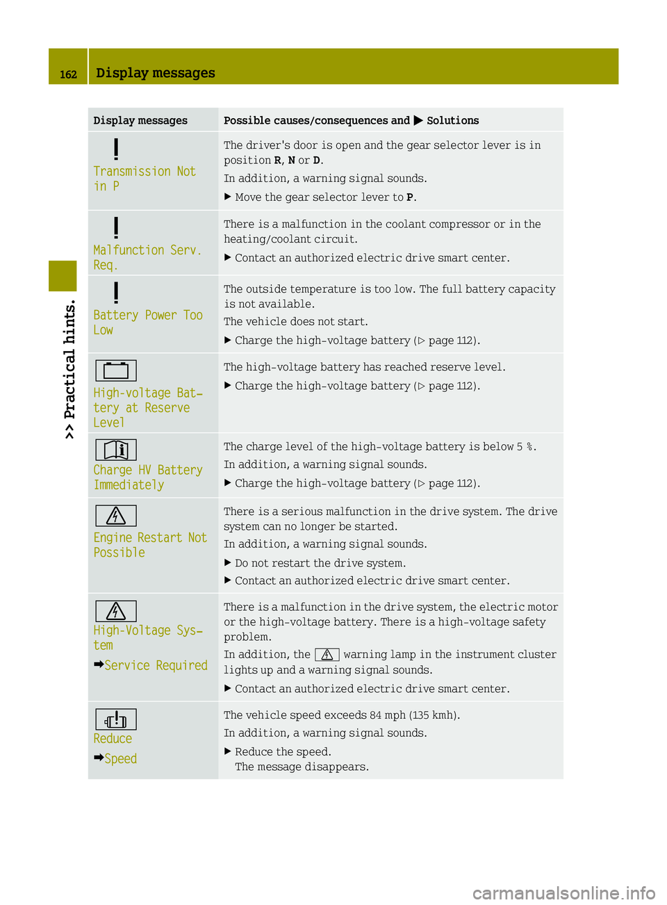
Display messages Possible causes/consequences and
0050
0050Solutions 0068
Transmission Not Transmission Not
in P in P The driver's door is open and the gear selector lever is in
position
R,Nor D.
In addition, a warning signal sounds.
X Move the gear selector lever to P.0068
Malfunction Serv. Malfunction Serv.
Req. Req. There is a malfunction in the coolant compressor or in the
heating/coolant circuit.
X
Contact an authorized electric drive smart center. 0068
Battery Power Too Battery Power Too
Low Low The outside temperature is too low. The full battery capacity
is not available.
The vehicle does not start.
X
Charge the high‑voltage battery (Y page 112).00FF
High-voltage Bat‐ High-voltage Bat‐
tery at Reserve tery at Reserve
Level Level The high‑voltage battery has reached reserve level.
X
Charge the high‑voltage battery (Y page 112).0051
Charge HV Battery Charge HV Battery
Immediately Immediately The charge level of the high‑voltage battery is below 5 %.
In addition, a warning signal sounds.
X
Charge the high‑voltage battery (Y page 112).0075
Engine Engine
Restart
Restart Not
Not
Possible
Possible There is a serious malfunction in the drive system. The drive
system can no longer be started.
In addition, a warning signal sounds.
X
Do not restart the drive system.
X Contact an authorized electric drive smart center. 0075
High-Voltage Sys‐ High-Voltage Sys‐
tem tem
0096Service Required
Service Required There is a malfunction in the drive system, the electric motor
or the high‑voltage battery. There is a high‑voltage safety
problem.
In addition, the
0075warning lamp in the instrument cluster
lights up and a warning signal sounds.
X Contact an authorized electric drive smart center. 00ED
Reduce Reduce
0096Speed
Speed The vehicle speed exceeds 84 mph (135 kmh).
In addition, a warning signal sounds.
X
Reduce the speed.
The message disappears. 162
Display messages>> Practical hints.
Page 165 of 222

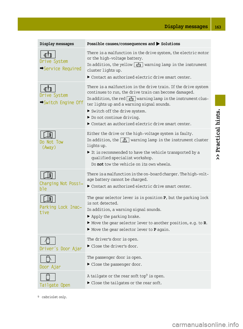
Display messages Possible causes/consequences and
0050
0050Solutions 00ED
Drive System Drive System
0096Service Required
Service Required There is a malfunction in the drive system, the electric motor
or the high‑voltage battery.
In addition, the yellow
00EDwarning lamp in the instrument
cluster lights up.
X Contact an authorized electric drive smart center. 00ED
Drive System Drive System
0096Switch
Switch Engine EngineOff
Off There is a malfunction in the drive train. If the drive system
continues to run, the drive train can become damaged.
In addition, the red
00EDwarning lamp in the instrument clus-
ter lights up and a warning signal sounds.
X Switch off the drive system.
X Do not continue driving.
X Contact an authorized electric drive smart center. 0051
Do Not Tow Do Not Tow
(Away)
(Away) Either the drive or the high‑voltage system is faulty.
In addition, the
0075warning lamp in the instrument cluster
lights up.
X It is recommended to have the vehicle transported by a
qualified specialist workshop.
Do not tow the vehicle on its own wheels. 0051
Charging Charging
Not
NotPossi‐
Possi‐
ble
ble There is a malfunction in the on-board charger. The high‑volt-
age battery cannot be charged.
X
Contact an authorized electric drive smart center. 0051
Parking Lock Inac‐ Parking Lock Inac‐
tive tive The gear selector lever is in position
P, but the parking lock
is not detected.
In addition, a warning signal sounds.
X Apply the parking brake.
X Move the gear selector lever to another position, e.g. to R.
X Move the gear selector lever to Pagain. 00DA
Driver´s Door Ajar Driver´s Door Ajar The driver’s door is open.
X
Close the driver’s door. 00DB
Door Ajar Door Ajar The passenger door is open.
X
Close the passenger door. 00D9
Tailgate Open Tailgate Open A tailgate or the rear soft top
9
is open.
X Close the tailgates or the rear soft. 9
cabriolet only. Display messages
163>> Practical hints. Z
Page 204 of 222

Jump start assistance
Your vehicle’s 12-volt battery is located in the passenger footwell below the footrest
(Y page 199).
For jump starting, use the terminals of the battery, keeping the leads connected.
X Make sure the two vehicles do not touch.
X Switch off all electrical consumers.
X Engage the parking brake.
X Move the gear selector lever to park position P.
X Switch off the drive system.
X Get access to the battery in the passenger footwell (Y page 199).
X Remove the positive terminal cover. Position
0083represents the charged battery of another vehicle or an equivalent starter
pack.
! Never invert the terminal connections!
X Connect positive terminal 0043of charged battery 0083with positive terminal 0044of your
vehicle’s battery 0084with a jumper cable. Clamp the jumper cable to positive termi-
nal 0043of charged battery 0083first.
X Start the engine of the vehicle with charged battery 0083.
X Connect negative terminal 0087of charged battery 0083with negative terminal 0085of your
vehicle’s battery 0084with a jumper cable. Clamp the jumper cable to negative terminal
0087 of charged battery 0083first.
X Start the drive system of your vehicle. You can now switch on minimal consumers. Do
not switch on large consumers such as the rear window defroster or headlamps. 202
Jump starting>> Practical hints.
Page 211 of 222

No. Accessory/Component Amperage Color
006D
CPC, shifter, brake force booster vacuum
pump 7.5 A Brown
006E
Coolant pumps 1 and 2, high-voltage battery 15 A Blue
006F
ESP
®
control unit 25 A Neutral
0070
Exterior lamp switch, turn signal lamp
switch, cockpit switch module, on-board
diagnostics socket, exterior rear view mir-
ror heating, anti-theft warning system,
rain-light sensor, charge level and power
gauges, central locking system, instrument
cluster, Tire Pressure Monitoring System
(TPMS), brake and turn signal lamps (left and
right) 10 A Red
0071
— — —
0072
— — —
0073
Safety circuit high-voltage battery 15 A Blue
0074
— — —
0075
Rear window wiper (coupé only) 15 A Blue
0076
ESP
®
control unit, EPS control unit, restraint
systems 10 A Red
0077
Electric drive components, engine control
unit, transmission control unit, on-board
diagnostics socket, sound generator 7.5 A Brown
0078
Air conditioning system, exterior rear view
mirror adjustment, washer pump, audio, seat
heating, wiper switch, cruise control, soft
top switch (cabriolet only), backup lamp 10 A Red
0079
Auxiliary power outlet 15 A Blue
007A
Left low‑beam headlamp 7.5 A Brown
007B
Right low‑beam headlamp 7.5 A Brown
007C
— — —
007D
Right high‑beam headlamp 7.5 A Brown
007E
Left high‑beam headlamp 7.5 A Brown
007F
Electric drive components 7.5 A Brown Fuses
209>> Practical hints. Z