charging SMART FORTWO COUPE ELECTRIC DRIVE 2013 Owners Manual
[x] Cancel search | Manufacturer: SMART, Model Year: 2013, Model line: FORTWO COUPE ELECTRIC DRIVE, Model: SMART FORTWO COUPE ELECTRIC DRIVE 2013Pages: 218, PDF Size: 2.69 MB
Page 6 of 218

1, 2, 3 ...
12-volt battery Charging ................................ 192
Indicator lamp ........................ 164
Notes ..................................... 190
Removing and installing ............192 A
ABS (Antilock Brake System) .............44
Indicator lamp ........................ 160
Accessory weight .......................... 137
Accidents Air bags .................................. 31
Address change .............................. 14
Air bags ....................................... 31
Children .................................. 31
Front, driver and passenger ......... 34
Front, passenger ....................... 34
Head-thorax ............................. 35
Knee bag .................................. 35
Passenger front air bag off
indicator lamp ..................... 26, 39
Safety guidelines ......................33
SRS indicator lamp ...................162
Thorax-pelvi s.......................... 36
Window curtain ......................... 36
Air conditioning with climate
control
Air distribution ....................... 98
Air recirculation mode ............... 99
Air vents ................................. 97
Air volume ............................... 99
Control panel ............................ 97
Defrosting ............................... 99
Notes ...................................... 95
Rear window defroster ................99
Switching on/off ....................... 97
Temperature ............................. 97
Air pressure
see Tire inflation pressure
Air pressure (tires) .......................138
Air vents ...................................... 97
Alarm system see Anti-theft systems
Ambient lighting* .......................... 65
Anticorrosion/antifreeze .........213, 214 Antiglare, Interior rear view
mirror
......................................... 59
Antilock Brake System see ABS
Anti-theft systems ......................... 46
Anti-theft warning system ...........47
Electronic immobilizer ..............46
Interior motion sensor ...............47
Tow-away alarm ......................... 47
Aquaplaning
see Hydroplaning
Armrest ........................................ 57
Aspect ratio (tires) .......................138
Audio system ................................. 91
Basic ...................................... 92
Navigation/multimedia ..............92
Automatic headlamp mode ................62
Automatic locking .......................... 51
AUX socket .................................... 93 B
Backrest see Seats
Backup lamp ................................. 174
Bar (air pressure unit) ...................138
Batteries .................................... 190
Battery Jump starting .......................... 193
Battery (key)
Replacing the transmitter
battery ................................... 171
Battery coolant ............................. 119
Bead (tire) .................................. 138
Brake fluid .................................. 121
Checking ................................ 121
Brake lamp .................................. 174
Brake pedal ................................... 76
Brakes ........................................ 142
Parking brake ........................... 75
Warning lamp .......................... 160
Bulbs
Fron t..................................... 173
Rear ...................................... 174
Replacing ............................... 1724
Index
Page 7 of 218
 ......17
California retail buyers and
lessees, important notice for ...........13
Cargo compartment cover blind ........100
CD player ...............................")
C
CAC (Customer Assistance Center) ......17
California retail buyers and
lessees, important notice for ...........13
Cargo compartment cover blind ........100
CD player ...................................... 91
Center console .............................. 25
Central locking Automati c................................ 51
Locking/unlocking from inside ....51
Certification label .......................208
Charge level gauge ......................... 79
Charging High-voltage battery ................108
Charging cable
Connecting .............................. 114
Control element ....................... 113
Storing .................................. 112
Children in the vehicle ...................40
Air bags .................................. 31
Indicator lamp, passenger front
air bag off ......................... 39, 168
Infant and child restraint
systems ................................... 41
OCS (Occupant Classification
System) ....................................37
Safety notes ............................. 40
Tether anchorage points .............43
Child safety
see Children in the vehicle
Cockpit ........................................ 20
Coin holder ................................. 102
Cold tire inflation pressure ...........138
Combination switch ........................64
Control system Charge and depart menu ..............86
Charging mode display ...............83
Contro llever ............................ 81
Introduction ............................. 81
Menus and submenu s................... 85
Message smenu .......................... 89
Multifunction display ................81
Odomete rmenu .......................... 85
Reset menu ............................... 86
Setting smenu ........................... 89Start menu
............................... 86
Time menu ............................... 90
Coolant
Anticorrosion/antifreeze .....213, 214
Battery ................................... 119
Capacities ........................ 212, 213
Drive system ........................... .119
Temperature warning lamp .........165
Coolant temperature ......................146
Cruise control ............................... 93
Curb weight ................................. 138
Customer Assistance Center (CAC) ......17 D
Dashboard see Instrument cluster
Data recording .............................. 18
Daytime running lamp mode ..............63
Deep water see Standing water
Defroster
Rear window ............................. 99
Windshield .............................. 99
Department of Transportation
see DOT
Direction of rotation (tires) ...........131
Door control panel ......................... 26
Door handles ................................. 26
Doors Locking/unlocking from outside ...51
Opening from inside ..................52
DOT (Department of
Transportation) ...................... 136, 138
Drinking and driving .....................141
Drive diagnostics Indicator lamp ........................ 166
Warnin glamp .......................... 166
Driving
Abroad ................................... 146
Coolant temperature .................146
Hydroplaning .......................... 144
Instructions ....................... 74, 141
In winter ................................ 145
Safety systems .......................... 44
Through standing water .............145
Tips, transmissio n.................... 78 Index
5
Page 8 of 218

Driving and parking
Safety notes ............................. 74
Driving safety systems ....................44
ABS ........................................ 44
ESP ®
....................................... 45
Hydraulic brake assistant ...........46 E
ECO indicator ............................... 83
Electrical system Improper work on or
modifications ........................... 15
Power outlet ............................ 106
Electronic immobilizer ..................46
Electronic Power Steering see EPS
Electronic Stability Program
see ESP ®
Emergency, in case of Hazard warning flasher ..........46, 66
Roadside Assistance ..................14
Emergency Tensioning Device
see ETD
Emission control
Information label .................... 208
System warranties ......................12
Engine
Electronic s............................. 206
Starting .................................. 74
Turning off .............................. 77
EPS (Electronic Power Steering)
Warning lamp .......................... 163
ESP ®
(Electronic Stability Program) ..45
Warning lamp .......................... 163
ETD (Emergency Tensioning Device) ...31
Safet yguidelines ...................... 33
Exterior lamp switch ......................62
Exterior lighting Overview ................................ 173
Exterior rear view mirrors ..............59 F
First-aid kit ............................... 154
Flat tire ..................................... 180
Fluids Capacities .............................. 212 Fog lamps
................................ 65, 173
Front air bags see Air bags
Front compartment ......................... 117
Front lamps Overview ................................ 173
Fuse chart ................................... 201
Fuses .......................................... 198 G
GAWR (Gross Axle Weight Rating) ......138
Global locking/unlocking ................51
Glove box .................................... 103
Gross Axle Weight Rating see GAWR
Gross Vehicle Weight
see GVW
Gross Vehicle Weight Rating
see GVWR
GVW (Gross Vehicle Weight) .............138
GVWR (Gross Vehicle Weight Rating) ..138 H
Halogen headlamps see Headlamps
Hazard warning flasher .................... 66
Headlamps Automatic headlamp mode ............ 62
Daytime running lamp mode .........63
High-beam flasher .....................64
High-beam headlamps ................. 64
Low-beam headlamps ..................62
Switch ..................................... 62
Head-thorax air bags ......................35
Heated exterior rear view mirrors .....59
Height adjustment Seats ...................................... 57
High-beam flasher ......................... 64
High-beam headlamps ................64, 173
Indicator lamp ........................ 164
High-mounted brake lamp ...............174
High-voltage battery Charg elevel gauge .................... 79
Charging (AC power socket) .........112
Charging (control system) ...........88
Charging (private wallbox) .........112 6
Index
Page 9 of 218

.................................. 114
Charging cable ........................ 112
Displaying available power .........82
ECO indicator ........................... 8")
Charging (public charging
station)
.................................. 114
Charging cable ........................ 112
Displaying available power .........82
ECO indicator ........................... 83
Intelligen tcharging
management ............................. 117
Introduction ........................... 108
Notes ..................................... 191
Problems with the charging
process .................................. 117
READY indicator ........................ 82
Warning label (wheel change) ......189
Warnin glamp .......................... 164
High-voltage disconnect device ........17
Hill-start assist system ..................78
Hydraulic brake assistant ................46
Hydroplaning ............................... 144I
Identification labels ....................208
Identification number, vehicle
(VIN) .......................................... 209
Infant and child restraint systems see Children in the vehicle
Inflation pressure
see Tires, Inflation pressure
Inside door handle ......................... 52
Instrument cluster .....................21, 23
Illumination ............................ 80
Lamps, indicator and warnin g..... 159
Instrument panel
see Instrument cluster
Instruments and controls
see Cockpit
Intelligent charging management
High-voltage battery .................117
Interior motion sensor ....................47
Interior rear view mirror ................59
Interior storage spaces see Storage compartments
Intermittent wiping
Rear window wiper .....................68
Windshield wipers .....................67 J
Jump-starting .............................. 193 K
Key ............................................. 50
Loss of ................................... 169
Replacing the transmitter
battery ................................... 171
Kilopascal (air pressure unit) .........138
Knee bag ...................................... 35 L
Labels ........................................ 208
Emission control information .....208
Lamps, exterior
Exterior lamp switch ..................62
Switching on/off ....................... 62
Lamps, indicator and warning
12-volt-battery ........................ 164
ABS ....................................... 160
Brakes ................................... 160
Coolant temperature .................165
Drive diagnostics ....................166
EPS ........................................ 163
ESP ®
...................................... 163
Fog lamps ................................ 65
High-beam headlamps ...............164
High-voltage battery ................164
Low-beam headlamps .................164
Low tire pressure/TPMS
malfunction telltal e................. 166
Overview (kilometers) ................24
Overview (miles) ....................... 22
Passenger front air bag off ....34, 168
Seat belt telltale ..................... 161
SRS ....................................... .162
Turn signals ............................ 165
License plate lamps .......................174
Lighting ...................................... 62
Ambient lighting* .....................65
Coming home function ................64
Daytime running lamp mode .........63
Exterior .................................. 62
Interior .................................. 66
Loading
see Vehicle loading Index
7
Page 16 of 218

charge the high‑voltage battery when no
public charging station is available.
R The operating range of your vehicle is
limited due to the availability of public
charging stations.
R Public charging stations may not be
available at all in some areas.
In light of the foregoing, proper care must
be exercised in the planning of a long
distance trip with the vehicle. smart is not
responsible for the availability of public
charging stations. Roadside Assistance
The smartmove Assistance (Canada) and
smart 1 service (USA) Program provides
factory trained technical help in the event
of a breakdown. Calls to the toll-free
Roadside Assistance number
1-800-762-7887 (in the USA)
1-877-627-8004 (in Canada)
will be answered by smart Customer
Assistance Representatives 24 hours a day,
365 days a year.
Roadside Assistance will be provided in
accordance with standard program
guidelines which include providing
service to the vehicle up to a reasonable
distance from a paved roadway. We will
make every effort to assist in a breakdown
situation, however, the accessibility of
your vehicle will be determined by our
authorized electric drive smart center
technician or the tow service provider on
a case-by-case basis and may be a factor in
our ability to respond.
Additional charges may be applicable for
a breakdown location determined not to be
a reasonably accessibl eroadside location
as determined by our authorized
technician and tow service provider.
For additional information refer to the
smart Roadside Assistance Program
brochure (USA) or the Warranty Booklet (Canada) in your vehicle literature
portfolio. Change of address or ownership
In the USA: If you change your address, be
sure to send in the “Information Change
Card” found in the Warranty Information
Booklet.
In Canada: If you change your address, be
sure to send in the “Change of Address
Notice” found in the Warranty Booklet, or
simply call the Customer Service at
1-800-387-0100.
Maintaining your current address
information with smart will enable us to
contact you should important new
information about the vehicle, such as
recalls, become available.
If you sell your smart, please leave all
literature with the vehicle to make it
available to the next operator.
In the USA: If you bought this vehicle used,
be sure to send in the “Information Change
Card” found in the Warranty Information
Booklet.
In Canada: If you bought this vehicle used,
be sure to send in the “Notice of Pre‑Owned
Vehicle Purchase” found in the Warranty
Booklet, or call the Customer Service at
1-800-387-0100. Operating your vehicle outside the USA
or Canada
If you plan to operate your vehicle in
foreign countries, please be aware that:
R Service facilities or replacement parts
may not be readily available.
R The AC power sockets in some countries,
especially overseas, require different
plugs on the charging cable.
R Charging stations may not be available. 14
>> Introduction.
Page 81 of 218

!
When the hill‑start assist system stops
braking the vehicle, it can roll
backwards.
If you open the driver’s door, the
hill‑start assist system is deactivated
and a warning signal sounds.
Your vehicle has a hill‑start assist system.
On uphill grades the hill‑start assist
system maintains the pressure in the brake
system for approximately one second after
you have released the brake pedal.
Therefore, you can start off smoothly
without the vehicle moving immediately
after releasing the brake pedal.
X Release the brake pedal.
X Apply sufficient pressure to the
accelerator pedal to drive off.
On uphill grades with higher inclination,
the hill-start assist system will release
the pressure in the brake system after
approximately two seconds. A warning
signal sounds and the transmission
position indicator shows a flashing N in
order to warn you of the vehicle rolling
backwards.
X Press the brake pedal.
X Release the brake pedal.
X Apply sufficient pressure to the
accelerator pedal to drive off.
i The hill‑start assist system is inactive
if you start off with the parking brake
engaged. Instrument cluster
Charge level and power gauges
0002
Charge level gauge
0003 Power gauge
The gauges can be turned by approximately
90°.
The illumination for both gauges comes on
when you switch on the ignition and the
exterior lighting.
Charge level gauge !
Do not hang any objects on the charge
level gauge.
This could cause the charge level gauge
to be torn from its mountings and be
damaged.
The charge level gauge 0002displays charge
status of the high-voltage battery as a
percentage.
When the High-voltage Battery at Reserve Level message appears in the
multifunction display while the drive
system is in operation, the high-voltage
battery has reached the reserve level.
i If the charge level of the high-voltage
battery has dropped below 20 %, recharge
it at:
R an AC power socket (Y page 112)
R a private wall box (Y page 112)
R a public charging station
(Y page 114) Instrument cluster
79>> Controls. Z
Page 82 of 218

influences the braking effect of the
electric motor.
In overr")
Power gauge
G
WARNING
The operating condition of the high-
voltage battery (e.g. not yet at normal
operating temperature or fully charged)
influences the braking effect of the
electric motor.
In overrun or braking mode, the motor's
braking effect may therefore be reduced or
may not be present at all.
As a result of the reduced engine braking
effect, you may cause an accident and
injure yourself or others.
Compensate for the reduced engine braking
effect by pressing the brake pedal
accordingly, as required.
! Do not hang any objects on the power
gauge.
This could cause the power gauge to be
torn from its mountings and be damaged.
Power gauge 0003contains two segments:
R Section right of 0
Power gauge 0003indicates the current
power that the drive system delivers to
the rear wheels. 100 % correspond to
55 kW peak power.
R Section left of 0
When you release the accelerator pedal
or when you depress the brake pedal, the
electric motor operates as a generator.
Electric current is produced and stored
in the high-voltage battery. As long as
the high-voltage battery is being
charged, the electric motor simulates an
engine brake.
When the pointer of power gauge 0003is in
the "OFF “position, the vehicle is not ready
to drive, because:
R the drive system has not been started
R the gear selector lever has not been
moved to position Nor Pwhen starting
the drive system R
the charging cable is connected to the
vehicle
R there is not enough power from the high-
voltage battery
R a problem occured in the high-voltage
system
After the drive system has been started, the
pointer of power gauge 0003moves to
position 0.READY appears in the
multifunction display (Y page 82). The
vehicle is ready to drive. Adjusting instrument cluster
illumination
You can adjust the illumination of
R the switches and dials in the instrument
cluster
R the radio
R the climate control panel
R the charge level and power gauges
Five illumination levels are available. X
Make sure the key is in starter switch
position 1.
X Switch on the parking lamps.
X To brighten or dim illumination: Press
button 0002on the instrument cluster
repeatedly until the desired setting is
reached.
The current setting is stored. 80
Instrument cluster>> Controls.
Page 85 of 218
. ECO indicator
ECO indicator
0002helps you to optimize
your driving style. The energy consumption
o")
By charging the high-voltage battery, the
reduced availability of power can be
improved (Y page 112). ECO indicator
ECO indicator
0002helps you to optimize
your driving style. The energy consumption
of your vehicle can be reduced and the
cruising range can be increased.
The calculated ECO value in percent
indicates if and how your driving style
differs from an ideal driving style (100 %).
This to provide you feedback to:
R your driving style when accelerating and
coasting
R the uniformity of your driving style
After aprolonged standstill of the vehicle,
ECO indicator display 0002always starts at
a value of 50 %.
The ECO-value is displayed:
R while driving
R if the key is in starter switch position
2. In place of the ECO display, battery charge
level 0002and charging time 0003appear , if:
R the high‑voltage battery is being
charged
R the key is in starter switch position 1. Charging mode display
When you switch off the ignition, you see
the display of the charging mode which is
currently set.
The charging mode is not changed after the
ignition has been switched off.
i If the multifunction display has
already gone out, you must turn the key to
starter switch position 1. Afterwards,
you can change the setting in the Charge and Depart menu (Y
page 86).
If you do not make a change, the last
selected entry is activated. If you have not
made any departure time settings in the
last 24 hours, the Instant Charge menu is
activated. Example illustration: Departure time selected
0002
Preset departure time
0003 Instant Charge menu
X To change the setting: press and hold the
control switch on the control lever up or
down until the desired mode is selected
in the multifunction display (Y page 81).
Additional information:
R Setting the departure time (Y page 86)
R Starting the charging process
immediately (Y page 88) Outside temperature
G
WARNING
The outside temperature display is not
designed as an ice-warning device and is
therefore unsuitable for that purpose.
Indicated temperatures just above the
freezing point do not guarantee that the Control system
83>> Controls.
Z
Page 89 of 218
This is useful:
R
if you wish to cool the interior of the
vehicle before driving
R if you wish to charge the vehicle at a
charging station/wallbox at the most
inexpensive electricity rate
With the "Air conditioning before start"
function, the vehicle interior is cooled
prior to a desired departure time.
Prerequisites:
R The doors and tailgate are closed.
R The charging cable for the high‑voltage
battery is connected to a power source
and inserted into the vehicle's power
socket.
R The high‑voltage battery has a
sufficient charge.
The maximum duration of "Air
conditioning before start" is 30 minutes.
Set the air distribution of your vehicle as
follows so that the "Air conditioning
before start" function has the greatest
effect:
R in summer, to the center and side vents
R in winter, onto the windshield and side
windows
Information on air distribution can be
found on (Y page 98).
The setting of the airflow regulator has no
influence on the "Air conditioning before
start" function.
i If the programmed time is too short, the
high‑voltage battery cannot be
completely charged. After setting the
departure time, the maximum charge
level which can be reached is then shown.
i If the high‑voltage battery is not
sufficiently charged and the "Air
conditioning before start" function is
activated, the high‑voltage battery is
charged first. When acharge level of at
least 20 % has been reached, the "Air
conditioning before start" function is
activated. This function then has priority over the charging of the
high‑voltage battery.
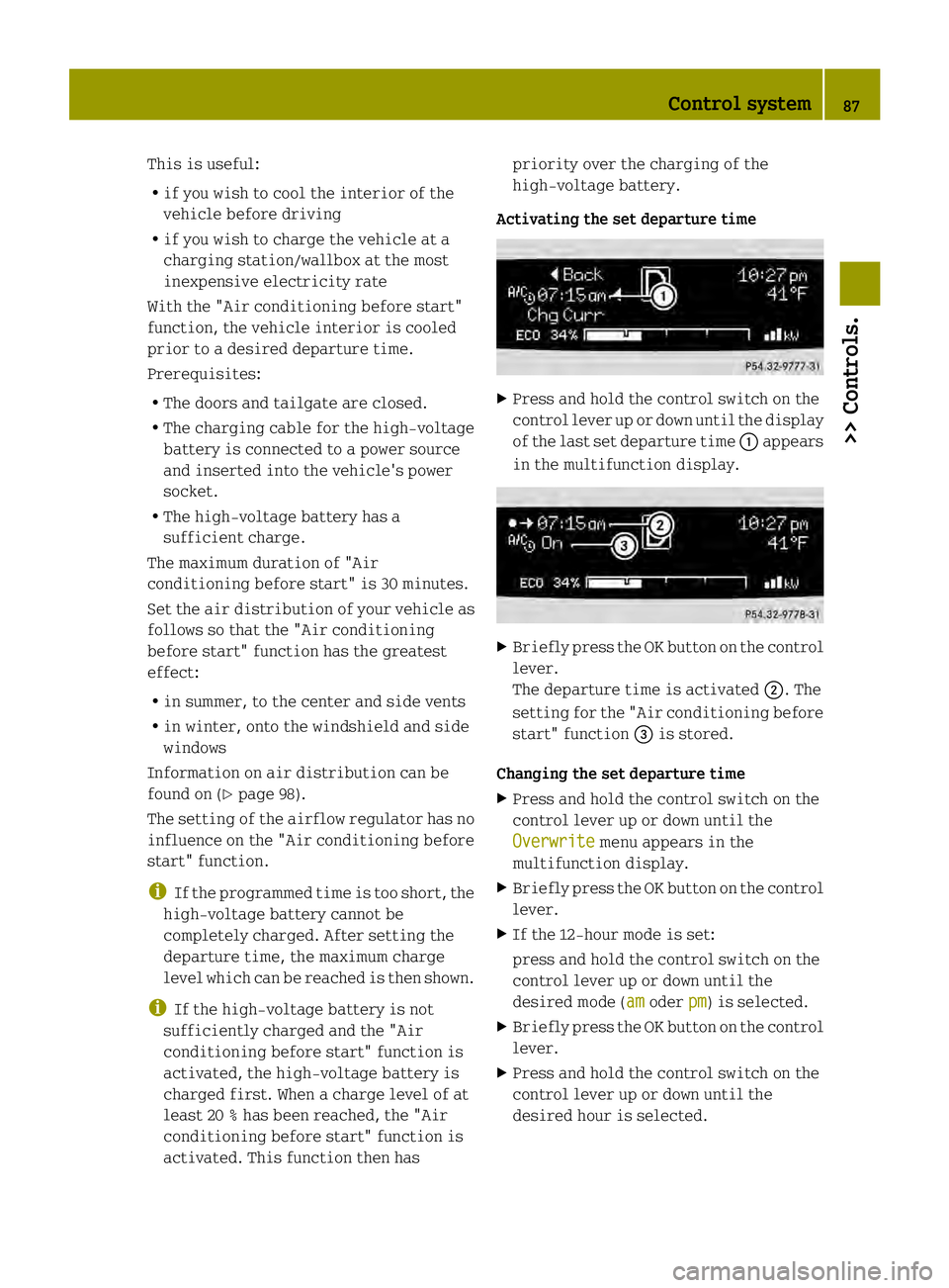
Activating the set departure time X
Press and hold the control switch on the
control lever up or down until the display
of the last set departure time 0002appears
in the multifunction display. X
Briefl ypress the OK button on the control
lever.
The departure time is activated 0003. The
setting for the "Air conditioning before
start" function 002Bis stored.
Changing the set departure time
X Press and hold the control switch on the
control lever up or down until the
Overwrite menu appears in the
multifunction display.
X Briefly press the OK button on the control
lever.
X If the 12-hour mode is set:
press and hold the control switch on the
control lever up or down until the
desired mode (am oder
pm ) is selected.
X Briefly press the OK button on the control
lever.
X Press and hold the control switch on the
control lever up or down until the
desired hour is selected. Control system
87>> Controls. Z
Page 90 of 218

X
Briefly press the OK button on the control
lever.
X Press and hold the control switch on the
control lever up or down until the "Air
conditioning before start" function is
activated or deactivated.
X Briefly press the OK button on the control
lever.
X Press and hold the control switch on the
control lever up or down until the "Air
conditioning before start" function is
activated or deactivated.
X Briefly press the OK button on the control
lever.
The new departure time is stored and
activated.
The "Air conditioning before start"
function is activated or deactivated.
Starting the charging process of the
high‑voltage battery immediately This function allows you to start the
charging process immediately. The
charging process begins as soon as the
charging cable is connected.
i The charging process also begins when
you insert the charging cable into the
vehicle's power socket. However, this is
only the case if you have not made any
departure time settings.
Information on the chargin gprocess can
be found on (Y page 112).
X Press and hold the control switch on the
control lever up or down until the
Instant Charge menu appears in the
multifunction display.
X Briefly press the OK button on the control
lever.
The charging process is started as soon
as the charging cable is connected.
i When you call up the Instant Chargemenu, the "Air conditioning before
start" function is not available. Setting the maximum charge current G
WARNING
When connected to a power supply socket, a
high electrical load during the charging
process can lead to overheating of the
external power supply. There is a risk of
fire.
Find out about the maximum permissible
current load of the external power supply
socket for the respective country at an
authorized electric drive smart center.
Check the maximum permissible charge
current on site before you begin the
charging process. Contact an authorized
electric drive smart center should you
require assistance. If necessary, adjust
the settings of your vehicle.
You can limit the charge current of the
high‑voltage battery. This can protect the
power supply from overloading. You can set
the limit either on the control unit of the
charging cable or via the control system.
The preset standard value is "Max". This
corresponds to the maximum available
charge current of the power supply.
Check the maximum permissible charge
current for the respective power supply
socket before charging the high‑voltage
battery.
The following values are available for
selection: 8 A, 10 A, 12 A, Max. The last value
set remains stored until a chang eis made.
X Press and hold the control switch on the
control lever up or down until the
Charge Current menu appears in the
multifunction display.
X Briefly press the OK button on the control
lever.
X Press and hold the control switch on the
control lever up or down until the
desired amperage is selected.
X Briefly press the OK button on the control
lever.
The selected amperage is set. 88
Control system>> Controls.