maintenance SMART FORTWO COUPE ELECTRIC DRIVE 2014 Owners Manual
[x] Cancel search | Manufacturer: SMART, Model Year: 2014, Model line: FORTWO COUPE ELECTRIC DRIVE, Model: SMART FORTWO COUPE ELECTRIC DRIVE 2014Pages: 222, PDF Size: 16.17 MB
Page 10 of 222
Overview (kilometers)
................26
Overview (miles) ....................... 24
Passenger front air bag off ....36, 175
Seat belt telltale .....................168
SRS ........................................ 169
Turn signals ............................ 172
License plate lamps .......................181
Lighting ...................................... 64
Ambient lighting* .....................67
Coming home function ................66
Daytime running lamp mode .........65
Exterior .................................. 64
Interior .................................. 68
Loading
see Vehicle loading
Locking the vehicle ........................52
Manually ................................. 177
Loss of
Key ........................................ 176
Service and Warranty Informa-
tion booklet ............................ 212
Low-beam headlamps .................64, 180
Exterior lamp switch ..................64
Indicator lamp .........................1 71
Switching on ............................ 64M
Maintenance .................................. 14
Manual headlamp mode (Low-beam
headlamps) ................................... 64
Maximum loaded vehicle weight .......144
Maximum load rating (tires) ............144
Maximum permissible tire infla-
tion pressure ............................... 144
Mirrors Exterior rear view mirrors ..........61
Interior rear view mirror ............61 N
Normal occupant weight .................145
Number, vehicle identification
(VIN) .......................................... 215 O
Occupant Classification System see OCS (Occupant Classifica-
tion System)
Occupant distribution ...................145
Occupant safety Air bags .................................. 33
Children and air bags ................33
Children in the vehicle ..............42
Infant and child restraint sys-
tems ....................................... 43
Introduction ............................ 30
OCS (Occupant Classification
System) ................................... 39
Passenger front air bag off
indicator lamp ......................... 39
Seat belts ............................ 31, 35
SRS indicator lamp, malfunction .169
OCS (Occupant Classification Sys-
tem) ............................................ 39
Self-test ................................. 42
On-board Diagnostics Socket (OBD) ...213
Online access .............................. 120
Operating range ............................. 14
Operating safety ............................ 16
Outside temperature display ............87
Overhead control panel ...................28 P
Paintwork care ............................. 157
Panic alarm .................................. 45
Parcel nets ............................ 104, 107
Parking ........................................ 77
Parking brake ................................ 77
Parking lamps .............................. 180
Parts service ............................... 212
PASS AIR BAG OFF indicator lamp see Passenger front air bag off
indicator lamp
Passenger front air bag ...................36
Passenger front air bag off indica-
tor lamp ............................. 28, 36, 175
Passenger safety see Occupant safety
Passenger seat .............................. .59
Pedals ........................................ 1478
Index
Page 11 of 222
Power assistance
.......................... 147
Power gauge .................................. 81
Power outlet ................................. 110
Power washer ................................ 156
Practical hints Display message s..................... 161
Flat tire ................................. 187
Fuses ..................................... 205
Jump starting .......................... 200
Replacing bulbs ....................... 179
Replacing transmitter battery ....178
Replacing wiper blades .............185
Towing ................................... 203
Unlocking/locking manually .......177
Warning and indicator
lamps ............................... 166, 175
What to do if ............................ 166
Where will I find... ?................. 160
Problems with your vehicle ..............18
Product information .......................13
Production options weight ..............145
PSI (air pressure unit) ...................145 R
Radio .......................................... 95
Radio transmitters ........................ 152
Rain-light sensor .......................... 69
READY indicator ............................ 87
Rear lamps Overview ................................ 181
Rear window defroster ...................103
Rear window wiper/washer ...............70
Replacing wiper blade ..............185
Recommended tire inflation pres-
sure ..................................... 128, 145
Remote control see Key
Replacing bulbs ............................ 179
Reporting safety defects ..................18
Restraint systems see Occupant safety
Rims ..................................... 145, 216
Roadside Assistance .......................15
Roof see Soft top system S
Safety Driving safety systems ...............46
Occupant safety ......................... 30
Reporting defects ......................18
Safety belts
see Seat belts
Saving energy .............................. 149
Seat belt force limiter .................... 33
Seat belts ..................................... 31
Children in the vehicle ..............42
Fastening ................................ 62
Proper use of ............................ 31
Safety guidelines ......................35
Safety notes .............................. 31
Telltale ................................. 168
Seat heating ................................. 60
Seating capacity .......................... 134
Seats ........................................... 58
Adjustment ............................... 58
Armrest ................................... 59
Heating ................................... 60
Passenger seat .......................... 59
Self-test
OCS (Occupant Classification
System) ................................... 42
SRS ......................................... 30
Service
see Maintenance
Service, parts .............................. 212
Service and warranty Booklet .................................. 212
Service flap ................................. 123
Service life (tires) .......................137
Setting the departure time (Control
system) ........................................ 90
Setting the maximum charge current
(Control system) ............................. 92
Side marker lamps ......................... 180
Sidewall (tires) ............................ 145
Side windows Operation ................................ 75
Signs and labels ........................... 214
smart surround sound system .............97
Snow chains ................................. 146 Index
9
Page 12 of 222
Snow tires
see Winter tires
Soft top system .............................. 70
Cleaning the soft top fabric .......157
Locking rear soft top manually ....178
Mounting the side rails ..............74
Opening and closing the rear
soft top ............................... 56, 72
Opening and closing the
retractable soft top ...............55, 71
Removing the side rails ..............73
Storing the side rails ................74
Sound package ............................... 97
SRS (Supplemental Restraint Sys-
tem)
Indicator lamp ........................ 169
Standing water, driving through ......152
Starter switch positions ..................57
Starting the engine ........................76
Steering wheel paddle shifters .........79
Storage compartments ....................106
Coin holder ............................. 106
Door pockets ........................... 106
Drawer ................................... 107
Glove box ................................ 106
in the tailgate ......................... 107
Parcel nets ............................. 107
Storage tray in center console ....107
Storage trays next to steering
wheel ..................................... 106
Storing tires ............................... 138
Sun screen ................................... 109
Sun visors ................................... 109T
Tailgate Closing ............................... 55, 57
Opening .............................. 54, 56
Tail lamps ................................... 181
Technical data Brake fluid ............................. 218
Coolant .................................. 219
Dimensions and weights .............215
Identification labels ................214
Rims and tires ......................... 216Service fluids and capacities
.....217
Windshield/rear window washer
system ................................... 218
Temperature
Coolant .................................. 152
Interior temperature ................101
Outside ................................... 87
Tether anchorage points
see Children in the vehicle
Thorax-pelvis side air bags .............38
Tightening torque Wheels ................................... 139
TIN (Tire Identification Num-
ber) ...................................... 142, 145
Tire and Loading Information plac-
ard ............................................ 133
Tire and loading terminology ..........143
Tire Identification Number see TIN
Tire inflation pressure
Checking ................................ 130
Important notes on ....................129
Placard on driver’s door B-pil-
lar ........................................ 133
Tire labeling ............................... 139
Tire load rating ........................... 145
Tire ply composition and material
used ........................................... 145
Tire Pressure Monitoring System
(TPMS) ........................................ 131
Tire repair kit ....................... 160, 187
Tires .................................... 127, 216
Air pressure ........................... 128
Care and maintenance ................137
Cleaning ................................ 138
Direction of rotation, spinning ..137
Driving instructions ................150
Flat tire ................................. 187
Important notes on tire infla-
tion pressure .......................... 129
Inflation pressure ....................130
Information placard .................133
Inspection .............................. 137
Labeling ................................ 139
Load rating ............................. 145
Ply composition and material
used ...................................... 14510
Index
Page 15 of 222
Product information
We recommend using Genuine smart Parts as
well as conversion parts and accessories
explicitly approved by smart for your
vehicle model.
We have tested these parts to determine
their reliability, safety and special suit-
ability for smart vehicles.
We are unable to make an assessment for
other products and therefore cannot be
held responsible for them, even if in indi-
vidual cases an official approval or
authorization by governmental or other
agencies should exist. Use of such parts
and accessories could adversely affect the
safety, performance or reliability of your
vehicle. We strongly recommend that you
not use them.
Genuine smart Parts as well as conversion
parts and accessories approved by us are
available at your authorized electric drive
smart center. Due to the technical require-
ments of the smart fortwo electric drive
and its high-voltage power systems, the
vehicle should be serviced only at an
authorized electric drive smart center. In
addition, you will receive comprehensive
information on permissible technical
modifications and expert installations on
the operation and maintenance of the smart
fortwo electric drive. Operator’s Manual
This Operator’s Manual contains a great
deal of useful information. We urge you to
read it carefully and familiarize yourself
with the vehicle before driving.
For your own safety and longer service life
of the vehicle, we urge you to follow the
instructions and warnings contained in
this manual. Ignoring them could result in
damage to the vehicle or personal injury to
you or others. Vehicle damage caused by failure to follow instructions is not cov-
ered by the smart Limited Warranty.
Your vehicle may have some or all of the
equipment described in this manual.
Therefore, you may find explanations for
optional equipment not installed in your
vehicle. If you have any questions about the
operation of any equipment, your author-
ized electric drive smart center will be
glad to demonstrate the proper procedures.
We continuously strive to improve our
product, and ask for your understanding
that we reserve the right to make changes
in design and equipment. Therefore,
information, illustrations and descrip-
tions in this Operator’s Manual might dif-
fer from your vehicle.
Optional equipment is also described in
this manual, including operating instruc-
tions wherever necessary. Since they are
special-order items, the descriptions and
illustrations herein may vary slightly from
the actual equipment of your vehicle.
If there are any equipment details that are
not shown or described in this Operator’s
Manual, your authorized electric drive
smart center will be glad to inform you of
correct care and operating procedures.
The Operator’s Manual and Maintenance/
Warranty Booklet (USA only) or Service/
Warranty Booklet (Canada only) are impor-
tant documents and should be kept with the
vehicle.
Warranty information
The smart USA Warranty booklet (USA only)
or the Warranty booklet (Canada only) con-
tains detailed information about the war-
ranties covering your smart, including:
R smart USA Limited Warranty (USA only)
R New Vehicle Limited Warranty (Canada
only)
R Emission System Warranty
R Emission Performance Warranty >> Introduction.
13
Page 16 of 222
R
Corrosion Warranty
R California, Connecticut, Maine, Massa-
chusetts, New York, Pennsylvania, Rhode
Island, and Vermont Emission Control
System Warranty
R smartmove Assistance (Canada only)
R State Warranty Enforcement Laws (Lemon
Laws, USA only) Important notice for California retail
buyers and lessees of smart automo-
biles
Under California law you may be entitled
to a replacement of your vehicle or a refund
of the purchase price or lease price, if
Mercedes-Benz USA LLC and/or its author-
ized repair or service facilities fail to
fix one or more substantial defects or mal-
functions in the vehicle that are covered
by its express warranty after a reasonable
number of repair attempts. During the
period of 18 months from original delivery
of the vehicle or the accumulation of
18 000 miles (approximately 29 000 km) on
the odometer of the vehicle, whichever
occurs first, a reasonable number of repair
attempts is presumed for a retail buyer or
lessee if one or more of the following
occurs:
(1) the same substantial defect or mal- function results in a condition that is
likely to cause death or serious bodily
injury if the vehicle is driven, that
defect or malfunction has been subject
to repair two or more times, and you
have directly notified Mercedes-Benz
USA LLC in writing of the need for its
repair,
(2) the same substantial defect or mal- function of a less serious nature than
category (1) has been subject to repair
four or more times and you have directly notified us in writing of the
need for its repair, or
(3) the vehicle is out of service by reason of repair of the same or different sub-
stantial defects or malfunctions for a
cumulative total of more than 30 cal-
endar days.
Written notification should not be sent to
a dealer, it should be addressed to:
Mercedes-Benz USA LLC
One Mercedes Drive
Montvale, NJ 07645 Maintenance
The Scheduled Maintenance Guide (USA) and
Service Booklet (Canada) describes all the
necessary maintenance work which should
be performed at regular intervals. It is
important that you service your vehicle in
accordance with the prescribed mainte-
nance schedule. Failure to do so may render
your vehicle unsafe, it may affect the dura-
bility of the vehicle, and it may otherwise
void the limited, express warranty.
Always have the Scheduled Maintenance
Guide (USA) or Service Booklet (Canada)
with you when you take the vehicle to your
authorized electric drive smart center for
service. The service advisor will record
each service in the booklet for you. Operating range
If you plan a long distance trip, please be
aware that:
R You will need to have access to an AC
power socket or a private wallbox to 14
>> Introduction.
Page 18 of 222
Operating safety
G
WARNING
Some safety systems only function while the
drive system is switched on. You should
therefore never switch off the drive system
while driving. G
WARNING
Work improperly carried out on electronic
components and associated software could
cause them to cease functioning. Because
the vehicle’s electronic components are
interconnected, any modifications made
may produce an undesired effect on other
systems. Electronic malfunctions could
seriously impair the operating safety of
your vehicle.
See an authorized electric drive smart
center for repairs or modifications to
electronic components.
Improper work or modifications on other
vehicle systems could also have a negative
impact on the operating safety of the vehi-
cle. G
WARNING
Heavy blows against the vehicle underbody
or tires/wheels, for example when running
over an obstacle, road debris or a pothole,
may cause serious damage and impair the
operating safety of your vehicle.
If you feel a sudden significant vibration
or ride disturbance, or you suspect that
damage to your vehicle has occurred, you
should turn on your hazard warning flash-
ers, carefully slow down, and drive with
caution to an area which is a safe distance
from the road.
Inspect the vehicle underbody and tires/
wheels for possible damage. If the vehicle
appears unsafe, have it towed to the nearest
authorized electric drive smart center or
other maintenance or repair facility that
is qualified to work on smart electric vehi-
cles for further inspection or repairs. G
WARNING
A vehicle with an electric motor produces
significantly lower noise levels than a
vehicle with a combustion engine. Other
motorists or pedestrians, especially those
who are visually or hearing impaired, may
be unable to hear your vehicle while it is
in motion. This is particularly true when
driving at lower speeds and during parking
maneuvers. At all times, it is the respon-
sibility of the driver to be aware of their
surroundings, especially in these low
speed situations. Otherwise other road
users could be seriously or fatally injured.
Vehicles equipped with an Acoustic Vehi-
cle Indication* emit a certain noise. Thus,
your vehicle will be better noticed by other
road users at low speeds (Y page 48). Danger of electric shock
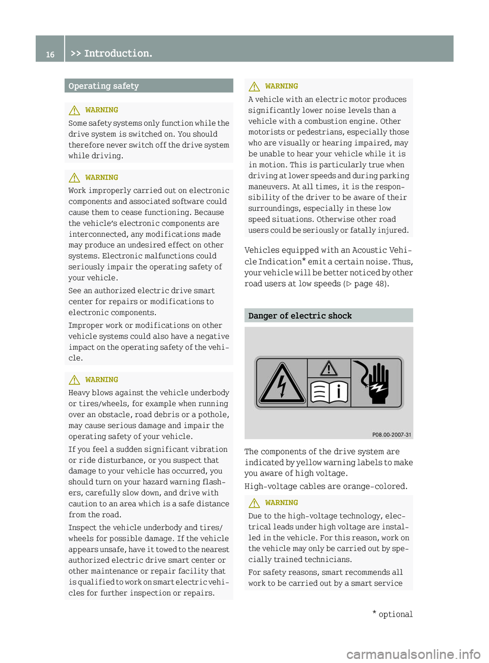
The components of the drive system are
indicated by yellow warning labels to make
you aware of high voltage.
High‑voltage cables are orange‑colored.
G
WARNING
Due to the high-voltage technology, elec-
trical leads under high voltage are instal-
led in the vehicle. For this reason, work on
the vehicle may only be carried out by spe-
cially trained technicians.
For safety reasons, smart recommends all
work to be carried out by a smart service 16
>> Introduction. * optional
Page 95 of 222
i
If the vehicle needs more time to charge
the high‑voltage battery than usual,
check the settings of the maximum per-
missible charge current. Messages menu
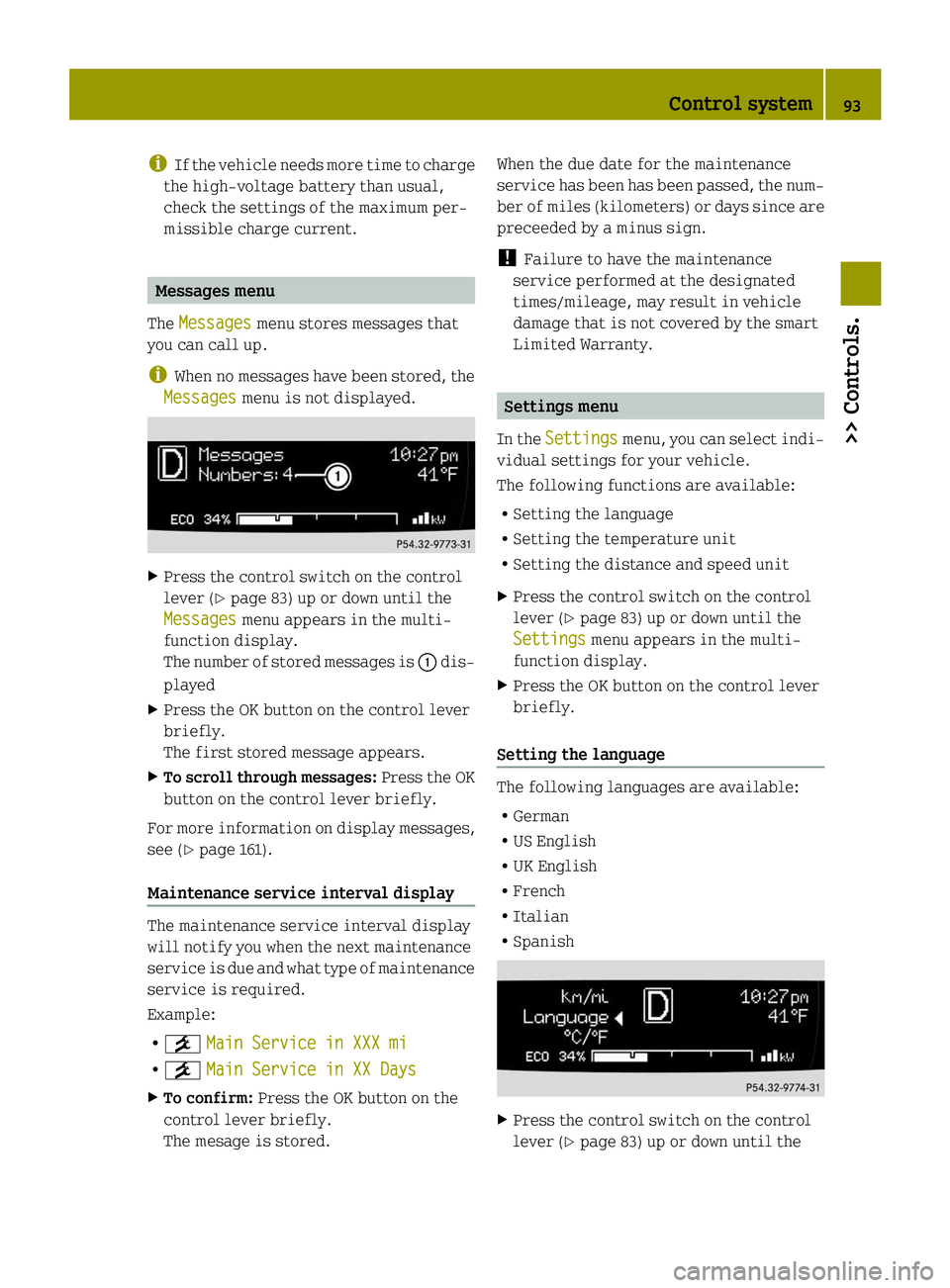
The Messages Messages menu stores messages that
you can call up.
i When no messages have been stored, the
Messages
Messages menu is not displayed. X
Press the control switch on the control
lever (Y page 83) up or down until the
Messages Messages menu appears in the multi-
function display.
The number of stored messages is 0043dis-
played
X Press the OK button on the control lever
briefly.
The first stored message appears.
X To scroll through messages: Press the OK
button on the control lever briefly.
For more information on display messages,
see (Y page 161).
Maintenance service interval display The maintenance service interval display
will notify you when the next maintenance
service is due and what type of maintenance
service is required.
Example:
R 009A Main Service in XXX mi
Main Service in XXX mi
R 009A Main Service in XX Days Main Service in XX Days
X To confirm: Press the OK button on the
control lever briefly.
The mesage is stored. When the due date for the maintenance
service has been has been passed, the num-
ber of miles (kilometers) or days since are
preceeded by a minus sign.
!
Failure to have the maintenance
service performed at the designated
times/mileage, may result in vehicle
damage that is not covered by the smart
Limited Warranty. Settings menu
In the Settings Settings menu, you can select indi-
vidual settings for your vehicle.
The following functions are available:
R Setting the language
R Setting the temperature unit
R Setting the distance and speed unit
X Press the control switch on the control
lever (Y page 83) up or down until the
Settings Settings menu appears in the multi-
function display.
X Press the OK button on the control lever
briefly.
Setting the language The following languages are available:
R
German
R US English
R UK English
R French
R Italian
R Spanish X
Press the control switch on the control
lever (Y page 83) up or down until the Control system
93>> Controls. Z
Page 116 of 222
ture range from
00F84‡(00F820 ¥) to 104 ‡
(40 ¥) .
When the vehicle is exposed to tempera-
tures below 00F813‡(00F825 ¥) for longer than
seven days, irreversible damage by frost
can occur.
Terms of use Observe the following notes:
R
exclusions of the high-voltage battery
terms of use in the battery rental con-
tract
R exclusions and limitations in the war-
ranty and guarantee documents, as well as
in the Service Booklet
R maintenance notes for the high-voltage
battery in the Service Booklet
Overvoltage protection !
Overvoltage in the on-board powersup-
ply system can damage the vehicle.
The vehicle is therefore equipped with a
protective device against overvoltage in
the power supply system. This protective
device can be activated in severe thun-
derstorms, for example, and lead to
security systems being triggered. This
function is used to protect the vehicle.
Once the security system has been reac-
tivated, the charging process continues
automatically.
Reactivate the security system after it has
been triggered. Otherwise the charging
process will not continue. The high-volt-
age battery is not being charged, which may
result in the vehicle not being ready to
start.
If you have secured other devices using the
same security system, they will also be
deactivated after this is triggered. Make
sure that these devices do function after
reactivating the security system. Charging cable and ‑connecter warming Observe the safety notes on (Y
page 112).
Charging cable and ‑connecter can become
warmed during charging process when con-
nected to a power source.
This warming is caused by
R high charge currents
R charging time
R transfer resistances at the plug contacts
R resistances of the charging cable
If the infrastructure of the power supply
system and charging cable are in good
order, the charging cable and ‑connecter
will only warm up within admissible
threshold.
Damaged charging cable plug or its con-
tacts may lead to warming above admissi-
ble threshold. In case of this, have the
cable, respectively power socket,
exchanged or disposed by a qualified elec-
trician. Charging at an AC power socket or a
private wallbox
Charging at an AC power socket G
WARNING
If you apply improperly installed power
sockets or adapters, extension cables or
similar to connect the charging cable to
power sockets, this may cause fire or lead
to electric shock. Risk of life!
In order to avoid the risk, please observe
the following:
R Connect the charging cable only to power
sockets which are
-properly installed
- approved by a qualified electrician
R For safety reasons only use charging
cables which have been supplied and
approved for the vehicle.
R Do not use a damaged charging cable. 114
High-voltage battery>> Operation.
Page 133 of 222
X
If you have overfilled the tire, release
tire inflation pressure by pushing the
metal stem of the valve with e.g. a tip of
a pen. Then recheck the tire inflation
pressure with the tire gauge.
X Install the valve cap.
X Repeat this procedure for each tire.
Tire Pressure Monitoring System
(TPMS)* Your vehicle may be equipped with a
Tire
Pressure Monitoring System (TPMS).
It monitors the tire inflation pressure in
all four tires. A warning is issued to alert
you to a decrease in pressure in one or more
of the tires.
The Tire Pressure Monitoring System
(TPMS) is equipped with a combination low
tire pressure/TPMS malfunction telltale in
the instrument cluster. Depending on how
the telltale illuminates, it indicates a low
tire pressure condition or a malfunction in
the TPMS system itself:
R If the telltale illuminates continuously,
one or more of your tires is significantly
underinflated. There is no malfunction
in the TPMS.
R If the telltale flashes for 60 seconds and
then stays illuminated, the TPMS system
itself is not operating properly.
The TPMS only functions on wheels that are
equipped with the proper electronic sen-
sors. G
WARNING
The TPMS does not indicate a warning for
wrongly selected inflation pressures.
Always adjust tire inflation pressure
according to the Tire and Loading Infor-
mation placard on the driver’s door B‑pil-
lar.
The TPMS is not able to issue a warning due
to a sudden dramatic loss of pressure (e.g.
tire blowout caused by a foreign object). In
this case bring the vehicle to a halt by carefully applying the brakes and avoiding
abrupt steering maneuvers.
G
WARNING
Each tire should be checked monthly when
cold and inflated to the inflation pressure
recommended by the vehicle manufacturer
on the Tire and Loading Information plac-
ard. If your vehicle has tires of a different
size than the size indicated on the Tire and
Loading Information placard, you should
determine the proper tire inflation pres-
sure for those tires.
As an added safety feature, your vehicle has
been equipped with a tire pressure moni-
toring system (TPMS) that illuminates a low
tire pressure telltale when one or more of
your tires is significantly underinflated.
Accordingly, when the low tire pressure
telltale illuminates, you should stop and
check your tires as soon as possible, and
inflate them to the proper pressure. Driv-
ing on a significantly underinflated tire
causes the tire to overheat and can lead to
tire failure.
Underinflation also increases energy con-
sumption, reduces tire tread life, and may
affect the vehicle’s handling and stopping
ability. Please note that the TPMS is not a
substitute for proper tire maintenance,
and it is the driver’s responsibility to
maintain correct tire pressure, even if
underinflation has not reached the level to
trigger illumination of the TPMS low tire
pressure telltale.
Your vehicle has also been equipped with a
TPMS malfunction indicator to indicate
when the system is not operating properly.
The TPMS malfunction indicator is com-
bined with the low tire pressure telltale.
When the system detects a malfunction, the
telltale will flash for approximately
1 minute and then remain continuously
illuminated.
This sequence will continue upon subse-
quent vehicle start-ups as long as the mal- Tires and wheels
131>> Operation.
* optional Z
Page 139 of 222
For more information on tire load rating
(Y page 140).
For information on calculating total and
cargo load capacities (Y page 135).Direction of rotation
Unidirectional tires offer added advan-
tages, such as better hydroplaning per-
formance. To benefit, however, you must
make sure the tires rotate in the direction
specified.
An arrow on the sidewall indicates the
intended direction of rotation (spinning)
of the tire. Tire care and maintenance
G
WARNING
Regularly check the tires for damage. Dam-
aged tires can cause tire inflation pres-
sure loss. As a result, you could lose control
of your vehicle.
Worn, old tires can cause accidents. If the
tire tread is badly worn, or if the tires have
sustained damage, replace them.
Check the tire inflation pressure at least
once a month. For more information on
checking tire inflation pressure, see
“Recommended tire inflation pressure”
(Y page 128).
Tire inspection Every time you check the tire inflation
pressure, you should also inspect your
tires for the following
R
excessive treadwear (Y page 137)
R cord or fabric showing through the tire’s
rubber
R bumps, bulges, cuts, cracks or splits in
the tread or side of the tire
Replace the tire if you find any of the above
conditions. Life of tire G
WARNING
Tires should be replaced after 6 years,
regardless of the remaining tread.
The service life of a tire is dependent upon
varying factors including but not limited
to
R driving style
R tire inflation pressure
R distance driven
Tread depth G
WARNING
Although the applicable federal motor
vehicle safety laws consider a tire to be
worn when the treadwear indicators (TWI)
become visible at approximately 1
/ 16 in
(1.6 mm), we recommend that you do not allow
your tires to wear down to that level. As
tread depth approaches 1
/ 8 in (3 mm), the
adhesion properties on a wet road are
sharply reduced.
Depending upon the weather and/or road
surface (conditions), the tire traction var-
ies widely.
Do not allow your tires to wear down too far.
Adhesion properties on wet roads are
sharply reduced at tread depths of less
than 1
/ 8 in (3 mm).
Treadwear indicators (TWI) are required by
law. These indicators are located in six
places on the tread circumference and
become visible at a tread depth of approx-
imately 1
/ 16 in (1.6 mm), at which point the
tire is considered worn and should be
replaced.
Recommended minimum tire tread depth:
Summer tires 1
/ 8 in (3 mm)
Winter tires 1
/ 6 in (4 mm) Tires and wheels
137>> Operation. Z