wheel size SMART FORTWO COUPE ELECTRIC DRIVE 2014 Owners Manual
[x] Cancel search | Manufacturer: SMART, Model Year: 2014, Model line: FORTWO COUPE ELECTRIC DRIVE, Model: SMART FORTWO COUPE ELECTRIC DRIVE 2014Pages: 222, PDF Size: 16.17 MB
Page 13 of 222
Problems under-/overinflation
...130
Retreads ................................. 127
Rims and tires (technical data) ...216
Rotation ................................. 139
Service life ............................ 137
Sizes ..................................... 216
Snow chains ............................ 146
Speed rating ................ 141, 145, 151
Storing .................................. 138
Temperature ...................... 130, 139
Terminology ............................ 143
Tire Identification Number ..142, 145
Tire Pressure Monitoring Sys-
tem (TPMS) .............................. 131
Traction ..................... 138, 145, 150
Tread ..................................... 145
Tread depth ....................... 137, 146
Treadwear indicators ..........137, 146
Vehicle maximum load on ...........146
Wheel change ........................... 195
Winter tires ...................... 146, 216
Tire speed rating ....................141, 145
Top tether see Children in the vehicle
Total load limit ........................... 145
Tow-away alarm ............................. 49
Towing ....................................... 203
Traction ................................ 145, 150
Transmission Driving tips ............................. 81
Hill-start assist system ..............81
Shifting procedure ....................79
Transmission position indicator ......84
Transmitting power values ..............213
Traveling abroad .......................... 153
Tread (tires) ................................ 145
Tread depth (tires) ..................137, 146
Treadwear indicators (tires) .....137, 146
Turning off the engine ....................79
Turn signal lamps ......................... 180
Turn signals ................................. 66
Indicator lamps ....................... 172 U
Uniform Tire Quality Grading
Standards .............................. 138, 146
Unlocking the vehicle .....................52
Manually ................................. 177
USB socket .................................... 96 V
Vehicle Bulbs ..................................... 179
Care ...................................... 153
Identification Number (VIN) .......215
Locking/unlockin g.................... 52
Modifications and alterations,
Operating safety ....................... 16
Towing ................................... 203
Unlocking/locking manually .......177
Vehicle Homepage
Data protection ........................ 121
Functions ............................... 121
General information .................120
Internet connection ..................122
Personal area .......................... 121
Vehicle Identification Number
(VIN) .......................................... 215
Vehicle lighting ........................... .64
Vehicle loading Instructions ............................ 108
Load limit .............................. 135
Roof rack ................................ 108
Terminology ............................ 143
Vehicle maximum load on the tire ....146
Vehicle specification ...................215
Vehicle washing see Vehicle care W
Warning signals Brake pads .............................. 177
Door ...................................... 176
Lighting ................................. 176
Parking .................................. 177
Parking brake .......................... 176
Seat belt reminder system ....168, 176
Warranty coverage ......................... 212 Index
11
Page 14 of 222
Warranty information
......................13
Washer fluid Mixing ratio ........................... 218
Refilling ................................ 126
Wiping .................................... 70
Washer jet nozzles ......................... 187
Washing the vehicle ......................153
Wheel change ............................... 195
Wheels, sizes ............................... 216
Wheels, Tires and .......................... 127
Where will I find...? Tire repair kit ........................ 160
Window curtain air bags ..................38
Windshield Washer fluid ....................... 70, 218
Wipers .................................... 69
Windshield wipers .......................... 69
Adjusting washer jet nozzles .......1 87
Rain-light sensor ..................... .69
Replacing wiper blades .............185
Winter driving
Driving instructions ................. 151
Snow chains ............................ 146
Tires ..................................... 146
Winter tires ........................... 146, 21612
Index
Page 36 of 222
G
WARNING
To reduce the risk of injury when the front
air bags inflate, it is very important for
the driver and passenger to always be in a
properly seated position and to wear their
respective seat belt.
For maximum protection in the event of a
collision always be in normal seated posi-
tion with your back against the backrest.
Fasten your seat belt and ensure it is prop-
erly positioned on your body.
Since the air bag inflates with considera-
ble speed and force, a proper seating and
hands on steering wheel position will help
to keep you at a safe distance from the air
bag.
Occupants who are unbelted, out of position
or too close to the air bag can be seriously
injured or killed by an air bag as it
inflates extremely quickly and with great
force:
R Sit properly belted in a position that is
as upright as possible with your back
against the seat backrest.
R Adjust the driver’s seat as far as possible
rearward, still permitting proper oper-
ation of vehicle controls. The distance
from the center of the driver’s breast-
bone to the center of the air bag cover on
the steering wheel must be at least
10 inches (25 cm) or more. You should be
able to accomplish this by adjustments to
the seat. If you have any problems, please
contact an authorized electric drive
smart center.
R Do not lean your head or chest close to the
steering wheel or dashboard.
R Keep hands on the outside of the steering
wheel rim. Placing hands and arms inside
the rim can increase the risk and poten-
tial severity of hand/arm injury when the
driver’s front air bag inflates. R
Adjust the passenger seat as far as pos-
sible rearward from the dashboard when
the seat is occupied.
R Occupants, especially children, should
never place their bodies or lean their
heads in the area of the door where the
head-thorax air bag (cabriolet) or
thorax-pelvis side air bag (coupé)
inflates. This could result in serious
injuries or death should the head-thorax
air bag (cabriolet) or thorax-pelvis side
air bag (coupé) be deployed. Always sit
as upright as possible, wear the seat belt
properly and use an appropriately sized
infant restraint, toddler restraint, or
booster seat recommended for the size
and weight of the child.
Failure to follow these instructions can
result in severe injuries to you or other
occupants.
If you sell your vehicle, it is important that
you make the buyer aware of this safety
information. Be sure to give the buyer this
Operator’s Manual.
i Air bags are designed to deploy only in
certain frontal impacts (front air bags
and knee bags), or side impacts (head-
thorax air bags, window curtain air bags
and thorax-pelvis air bags) which
exceed preset thresholds. Only during
these events will they provide their sup-
plemental protection.
The driver and passenger should always
wear their seat belts. Otherwise it is not
possible for air bags to provide their
supplemental protection.
In case of other types of impacts and
impacts below air bag deployment
thresholds, air bags will not deploy. The
driver and passenger will then be pro-
tected to the extent possible by a prop-
erly fastened seat belt. A properly fas-
tened seat belt is also needed to provide
the best possible protection in a roll-
over. 34
Occupant safety>> Safety.
Page 50 of 222
erwise seriously damage the brake sys-
tem which is not covered by the smart
Limited Warranty.
i The ESP ®
will only function properly if
you use wheels of the recommended tire
size (Y page 216). Hydraulic brake assistant
The hydraulic brake assistant operates in
emergency situations. If you apply the
brakes very quickly, the hydraulic brake
assistant automatically provides full
brake boost, thereby potentially reducing
the braking distance.
X Apply continuous full braking pressure
until the emergency braking situation is
over.
The ABS will prevent the wheels from
locking.
When you release the brake pedal, the
brakes function again as normal. The
hydraulic brake assistant is then deacti-
vated. G
WARNING
When the hydraulic brake assistant is mal-
functioning, the brake system is still func-
tioning normally, but without the addi-
tional brake boost that would normally be
provided during an emergency braking
maneuver. Therefore, the braking distance
may increase. G
WARNING
The hydraulic brake assistant cannot pre-
vent the natural laws of physics from acting
on the vehicle, nor can it increase braking
efficiency beyond that afforded by the con-
dition of the vehicle brakes and tires or the
traction afforded. The hydraulic brake
assistant cannot prevent accidents,
including those resulting from excessive
speed in turns, following another vehicle
too closely, or hydroplaning. Only a safe,
attentive, and skillful driver can prevent accidents. The capabilities of a hydraulic
brake assistant equipped vehicle must
never be exploited in a reckless or dan-
gerous manner which could jeopardize the
user’s safety or the safety of others.
Activating the hazard warning flasher
after an emergency braking maneuver
If you bring the vehicle to a complete stop
by strongly braking at a speed of more than
43 mph (70 km/h), the hazard warning
flasher comes on automatically as soon as
the vehicle is at a standstill. The hazard
warning flasher will remain on until it is
switched off using the hazard warning
flasher switch (Y page 68) or until the
speed of the vehicle has exceeded 6 mph
(10 km/h). Acoustic Vehicle Indication*
Vehicles with electric motors develop con-
siderably lower driving noises than vehi-
cles with combustion engines. Therefore
your vehicle in traffic might not be acous-
tically noticed by other road users in cer-
tain situations.
In order to avoid this, a built-in sound
generator emits a certain noise (Acoustic
Vehicle Indication) within a speed range
between 0 to 20 mph (30 km/h). Thus, other
road users, especially pedestrians and
bicycle riders can notice your vehicle bet-
ter. Acoustic Vehicle Indication can also
be heard inside of the vehicle.
The volume of Acoustic Vehicle Indication
depends on the current engine speed (rpm).
The stronger you accelerate, the louder the
noise. At speed of more than 20 mph
30 km/h the noise is switched off. From this
speed on the natural noises of the vehicle
are sufficient so that other road users can
notice the vehicle on time. 48
Driving safety systems>> Safety.
* optional
Page 60 of 222
Seats
Safety notes
G
WARNING
All seat adjustments, as well as fastening
of seat belts, must be done before the vehi-
cle is operated. G
WARNING
When adjusting the seat, make sure no one
becomes trapped.
Do not adjust the driver’s seat while driv-
ing. Adjusting the seat while driving could
cause the driver to lose control of the vehi-
cle.
Never ride in a moving vehicle with the seat
backrest in an excessively reclined posi-
tion as this can be dangerous. You could
slide under the seat belt in a collision. If
you slide under the seat belt, it could apply
force at the abdomen or neck, potentially
causing serious or fatal injuries. The seat
backrest and seat belts provide the best
restraint when the wearer is in a position
that is as upright as possible and seat belts
are properly positioned on the body.
Your seat must be adjusted so that you can
correctly fasten your seat belt.
Observe the following points:
R Adjust the seat backrest until your arms
are slightly angled when holding the
steering wheel.
R Adjust the seat to a comfortable seating
position that still allows you to reach the
accelerator/brake pedal safely. The
position should be as far back as possi-
ble with the driver still able to operate
the controls properly.
R Never place hands under the seat or near
any moving parts while a seat is being
adjusted.
Failure to do so could result in an accident
and/or serious personal injury.
Observe the notes on the air bag system. G
WARNING
Children 12 years old and under must be
seated and properly secured in an appro-
priately sized infant restraint, toddler
restraint, or booster seat recommended for
the size and weight of the child. For addi-
tional information, see “Children in the
vehicle”.
A child’s risk of serious or fatal injuries
is significantly increased if the child
restraints are not properly secured in the
vehicle and/or the child is not properly
secured in the child restraint. G
WARNING
Contact an authorized electric drive smart
center if the seats have become damaged.
The seat is an integral part of the vehicle’s
safety system in the same way as seat belts
and air bags. Damage to the seats may
reduce their ability to protect the occu-
pants in an accident. Seat adjustment
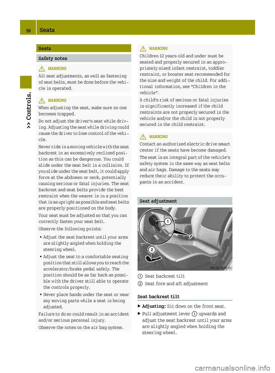
0043
Seat backrest tilt
0044 Seat fore and aft adjustment
Seat backrest tilt X
Adjusting: Sit down on the front seat.
X Pull adjustment lever 0043upwards and
adjust the seat backrest until your arms
are slightly angled when holding the
steering wheel. 58
Seats>> Controls.
Page 130 of 222
ommended rims and tires for summer and
winter operation. They can also offer
advice concerning tire service and pur-
chase. G
WARNING
Replace rims or tires with the same desig-
nation, manufacturer and type as shown on
the original part. For further information
contact an authorized electric drive smart
center. If incorrectly sized rims and tires
are mounted, the wheel brakes or suspen-
sion components can be damaged. Also, the
operating clearance of the wheels and the
tires may no longer be correct. G
WARNING
Worn, old tires can cause accidents. If the
tire tread is worn to minimum tread depth,
or if the tires have sustained damage,
replace them.
When replacing rims, only use genuine
smart wheel bolts specified for the partic-
ular rim type. Failure to do so can result in
the bolts loosening and possibly an acci-
dent.
Retreaded tires are not tested or recom-
mended by smart, since previous damage
cannot always be recognized on retreads.
The operating safety of the vehicle cannot
be assured when such tires are used. G
WARNING
If you feel a sudden significant vibration
or ride disturbance, or you suspect that
possible damage to your vehicle has occur-
red, you should turn on the hazard warning
flashers, carefully slow down, and drive
with caution to an area which is a safe dis-
tance from the road.
Inspect the tires and the vehicle underbody
for possible damage. If the vehicle or tires
appear unsafe, have the vehicle towed to the
nearest authorized electric drive smart
center or tire dealer for repairs. G
WARNING
Do not drive with a flat tire. A flat tire
affects the ability to steer or brake the
vehicle. You could lose control of the vehi-
cle. Continued driving with a flat tire or
driving at high speed with a flat tire will
cause excessive heat build-up and possibly
a fire.
Modifications to the brake system and
wheels and the use of brake dust rings are
not permissible. Important guidelines
R Only use sets of tires and rims of the same
type and make.
R Tires must be of the correct size for the
rim.
R Break in new tires for approximately
60 miles (100 km) at moderate speeds.
R Regularly check the tires and rims for
damage. Dented or bent rims can cause
tire pressure loss and damage to the tire
beads.
R If vehicle is heavily loaded, check tire
inflation pressure and correct as
required.
R Do not allow your tires to wear down too
far. Adhesion properties on wet roads are
sharply reduced at tread depths of less
than 1
/ 8 in (3 mm). Recommended tire inflation pressure
G
WARNING
Follow recommended tire inflation pres-
sures.
Do not underinflate tires. Underinflated
tires wear excessively and/or unevenly,
adversely affect handling and energy con-
sumption of the vehicle, and are more
likely to fail from being overheated.
Do not overinflate tires. Overinflated
tires can adversely affect handling and 128
Tires and wheels>> Operation.
Page 133 of 222
X
If you have overfilled the tire, release
tire inflation pressure by pushing the
metal stem of the valve with e.g. a tip of
a pen. Then recheck the tire inflation
pressure with the tire gauge.
X Install the valve cap.
X Repeat this procedure for each tire.
Tire Pressure Monitoring System
(TPMS)* Your vehicle may be equipped with a
Tire
Pressure Monitoring System (TPMS).
It monitors the tire inflation pressure in
all four tires. A warning is issued to alert
you to a decrease in pressure in one or more
of the tires.
The Tire Pressure Monitoring System
(TPMS) is equipped with a combination low
tire pressure/TPMS malfunction telltale in
the instrument cluster. Depending on how
the telltale illuminates, it indicates a low
tire pressure condition or a malfunction in
the TPMS system itself:
R If the telltale illuminates continuously,
one or more of your tires is significantly
underinflated. There is no malfunction
in the TPMS.
R If the telltale flashes for 60 seconds and
then stays illuminated, the TPMS system
itself is not operating properly.
The TPMS only functions on wheels that are
equipped with the proper electronic sen-
sors. G
WARNING
The TPMS does not indicate a warning for
wrongly selected inflation pressures.
Always adjust tire inflation pressure
according to the Tire and Loading Infor-
mation placard on the driver’s door B‑pil-
lar.
The TPMS is not able to issue a warning due
to a sudden dramatic loss of pressure (e.g.
tire blowout caused by a foreign object). In
this case bring the vehicle to a halt by carefully applying the brakes and avoiding
abrupt steering maneuvers.
G
WARNING
Each tire should be checked monthly when
cold and inflated to the inflation pressure
recommended by the vehicle manufacturer
on the Tire and Loading Information plac-
ard. If your vehicle has tires of a different
size than the size indicated on the Tire and
Loading Information placard, you should
determine the proper tire inflation pres-
sure for those tires.
As an added safety feature, your vehicle has
been equipped with a tire pressure moni-
toring system (TPMS) that illuminates a low
tire pressure telltale when one or more of
your tires is significantly underinflated.
Accordingly, when the low tire pressure
telltale illuminates, you should stop and
check your tires as soon as possible, and
inflate them to the proper pressure. Driv-
ing on a significantly underinflated tire
causes the tire to overheat and can lead to
tire failure.
Underinflation also increases energy con-
sumption, reduces tire tread life, and may
affect the vehicle’s handling and stopping
ability. Please note that the TPMS is not a
substitute for proper tire maintenance,
and it is the driver’s responsibility to
maintain correct tire pressure, even if
underinflation has not reached the level to
trigger illumination of the TPMS low tire
pressure telltale.
Your vehicle has also been equipped with a
TPMS malfunction indicator to indicate
when the system is not operating properly.
The TPMS malfunction indicator is com-
bined with the low tire pressure telltale.
When the system detects a malfunction, the
telltale will flash for approximately
1 minute and then remain continuously
illuminated.
This sequence will continue upon subse-
quent vehicle start-ups as long as the mal- Tires and wheels
131>> Operation.
* optional Z
Page 135 of 222
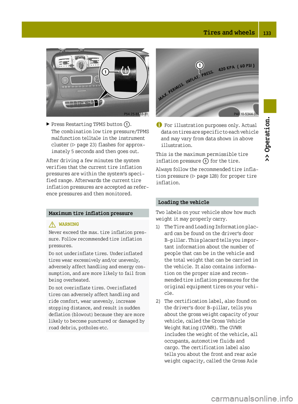
X
Press Restarting TPMS button 0043.
The combination low tire pressure/TPMS
malfunction telltale in the instrument
cluster (Y page 23) flashes for approx-
imately 5 seconds and then goes out.
After driving a few minutes the system
verifies that the current tire inflation
pressures are within the system’s speci-
fied range. Afterwards the current tire
inflation pressures are accepted as refer-
ence pressures and then monitored. Maximum tire inflation pressure
G
WARNING
Never exceed the max. tire inflation pres-
sure. Follow recommended tire inflation
pressures.
Do not underinflate tires. Underinflated
tires wear excessively and/or unevenly,
adversely affect handling and energy con-
sumption, and are more likely to fail from
being overheated.
Do not overinflate tires. Overinflated
tires can adversely affect handling and
ride comfort, wear unevenly, increase
stopping distance, and result in sudden
deflation (blowout) because they are more
likely to become punctured or damaged by
road debris, potholes etc. i
For illustration purposes only. Actual
data on tires are specific to each vehicle
and may vary from data shown in above
illustration.
This is the maximum permissible tire
inflation pressure 0043for the tire.
Always follow the recommended tire infla-
tion pressure (Y page 128) for proper tire
inflation. Loading the vehicle
Two labels on your vehicle show how much
weight it may properly carry.
1) The Tire and Loading Information plac- ard can be found on the driver’s door
B‑pillar. This placard tells you impor-
tant information about the number of
people that can be in the vehicle and
the total weight that can be carried in
the vehicle. It also contains informa-
tion on the proper size and recom-
mended tire inflation pressures for the
original equipment tires on your vehi-
cle.
2) The certification label, also found on the driver’s door B‑pillar, tells you
about the gross weight capacity of your
vehicle, called the Gross Vehicle
Weight Rating (GVWR). The GVWR
includes the weight of the vehicle, all
occupants, automotive fluids and
cargo. The certification label also
tells you about the front and rear axle
weight capacity, called the Gross Axle Tires and wheels
133>> Operation. Z
Page 137 of 222
illustration. Refer to Tire and Loading
Information placard on vehicle for
actual data specific to your vehicle.
Steps for determining correct load limit
The following steps have been developed as
required of all manufacturers under
Title 49, Code of U.S. Federal Regulations,
Part 575 pursuant to the “National Traffic
and Motor Vehicle Safety Act of 1966”.
X Step 1: Locate the statement “The com-
bined weight of occupants and cargo
should never exceed XXXX kg or
XXXX lbs.” on your vehicle’s Tire and
Loading Information placard.
X Step 2: Determine the combined weight of
the driver and passenger that will be
riding in your vehicle.
X Step 3: Subtract the combined weight of
the driver and passenger from XXXX kilo-
grams or XXXX lbs.
X Step 4: The resulting figure equals the
available amount of cargo and luggage
load capacity. For example, if the “XXXX”
amount equals 540 lbs and there will be
one 150 lbs passenger in your vehicle, the
amount of available cargo and luggage
load capacity is 390 lbs
(540 lbs - 150 lbs = 390 lbs).
X Step 5: Determine the combined weight of
luggage and cargo being loaded on the
vehicle. That weight may not safely
exceed the available cargo and luggage
load capacity calculated in step 4.
i The maximum cargo compartment load
is 110 lbs (50 kg).
The following table shows examples on how
to calculate total and cargo load capaci-
ties with varying seating configurations
and number and size of occupants. The fol-
lowing examples use a load limit of 540 lbs.
This is for illustration purposes only .
Make sure you are using the actual load
limit for your vehicle stated on the vehi-
cle’s Tire and Loading Information placard
(Y page 134). The higher the weight of all occupants, the
less cargo and luggage load capacity is
available. Tires and wheels
135>> Operation. Z
Page 141 of 222
The traction grades, from highest to low-
est, are AA, A, B, and C. Those grades rep-
resent the tire’s ability to stop on wet
pavement as measured under controlled
conditions on specified government test
surfaces of asphalt and concrete. A tire
marked C may have poor traction perform-
ance.
Temperature G
WARNING
The temperature grade for this tire is
established for a tire that is properly
inflated and not overloaded. Excessive
speed, underinflation, or excessive load-
ing, either separately or in combination,
can cause excessive heat build-up and pos-
sible tire failure.
The temperature grades are A (the highest),
B, and C, representing the tire’s resistance
to the generation of heat and its ability to
dissipate heat when tested under control-
led conditions on a specified indoor lab-
oratory test wheel. Sustained high temper-
ature can cause the material of the tire to
degenerate and reduce tire life, and
excessive temperature can lead to sudden
tire failure. The grade C corresponds to a
level of performance which all passenger
car tires must meet under the Federal Motor
Vehicle Safety Standard No. 109. Grades B
and A represent higher levels of perform-
ance on the laboratory test wheel than the
minimum required by law. Rotating tires
G
WARNING
Do not rotate front and rear wheels as they
have different dimensions, e.g. rim size,
wheel offset etc. Otherwise, the handling
can be affected and you could endanger
yourself and others. Thoroughly clean the mounting face of the
wheels and brake discs, i.e. the inner side
of the wheels/tires each time the wheels/
tires are changed. Check for and ensure
proper tire inflation pressure. G
WARNING
Have the tightening torque checked after
changing a wheel. Wheels could become
loose if not tightened with a torque of
81 lb‑ft (110 Nm).
Only use genuine smart wheel bolts speci-
fied for your vehicle’s rims.
For information on wheel change, see “Flat
tire” (Y page 187). Tire labeling
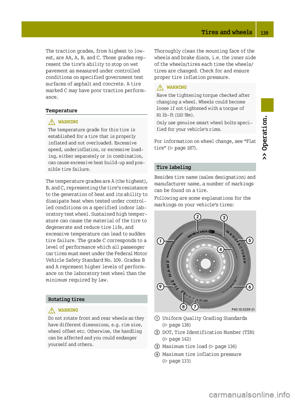
Besides tire name (sales designation) and
manufacturer name, a number of markings
can be found on a tire.
Following are some explanations for the
markings on your vehicle’s tires: 0043
Uniform Quality Grading Standards
(Ypage 138)
0044 DOT, Tire Identification Number (TIN)
(Ypage 142)
0087 Maximum tire load (Y page 136)
0085 Maximum tire inflation pressure
(Ypage 133) Tires and wheels
139>> Operation. Z