sensor SSANGYONG KORANDO 2012 Owners Manual
[x] Cancel search | Manufacturer: SSANGYONG, Model Year: 2012, Model line: KORANDO, Model: SSANGYONG KORANDO 2012Pages: 1082, PDF Size: 96.1 MB
Page 507 of 1082

02-8
Swirl control valve
It operates variably in accordance with the
engine load and rpm.
Refer to Chapter “Engine Control”.
Intake manifold
It is the passage for intake air when the swirl
vale is operating. The T-MAP sensor for
measuring the pressure and temperature of
pressurized air in turbocharger is installed on
the left top of intake manifold.
3. LAYOUT OF INTAKE SYSTEM
1) Overview
The intake system for D20DTF(Low CO2) engine is equipped with a throttle body which includes a flap.
This flap is controlled by an electrical signal to cut off the intake air entering to the engine when the
ignition switch is turned off. The intake manifold contains the swirl control valve and dual port system to
make the optimum turbulence. The T-MAP sensor is located on the left top of the intake manifold and
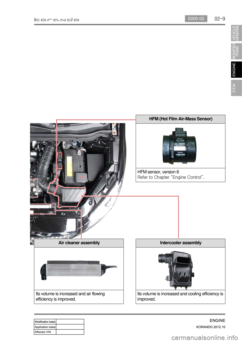
the HFM sensor for precise control is located at the rear side of air cleaner. To reduce the intake noise
and to improve the intake efficiency, the volume of air cleaner has been increased.
2) Components
Electric throttle body
Refer to Chapter “Engine Control”.
Page 508 of 1082

02-90000-00
HFM (Hot Film Air-Mass Sensor)
HFM sensor, version 6
Refer to Chapter “Engine Control”.
Air cleaner assembly
Its volume is increased and air flowing
efficiency is improved.Intercooler assembly
Its volume is increased and cooling efficiency is
improved.
Page 509 of 1082

14-30000-00
1. SPECIFICATIONS
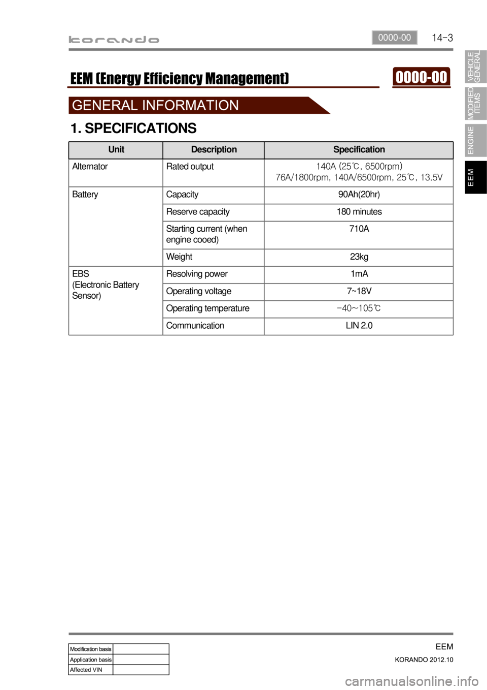
Alternator Rated output140A (25℃, 6500rpm)
76A/1800rpm, 140A/6500rpm, 25℃, 13.5V
Battery Capacity 90Ah(20hr)
Reserve capacity 180 minutes
Starting current (when
engine cooed)710A
Weight 23kg
EBS
(Electronic Battery
Sensor)Resolving power 1mA
Operating voltage 7~18V
Operating temperature-40~105℃
Communication LIN 2.0
Unit Description Specification
Page 522 of 1082

14-16
1. LAYOUT
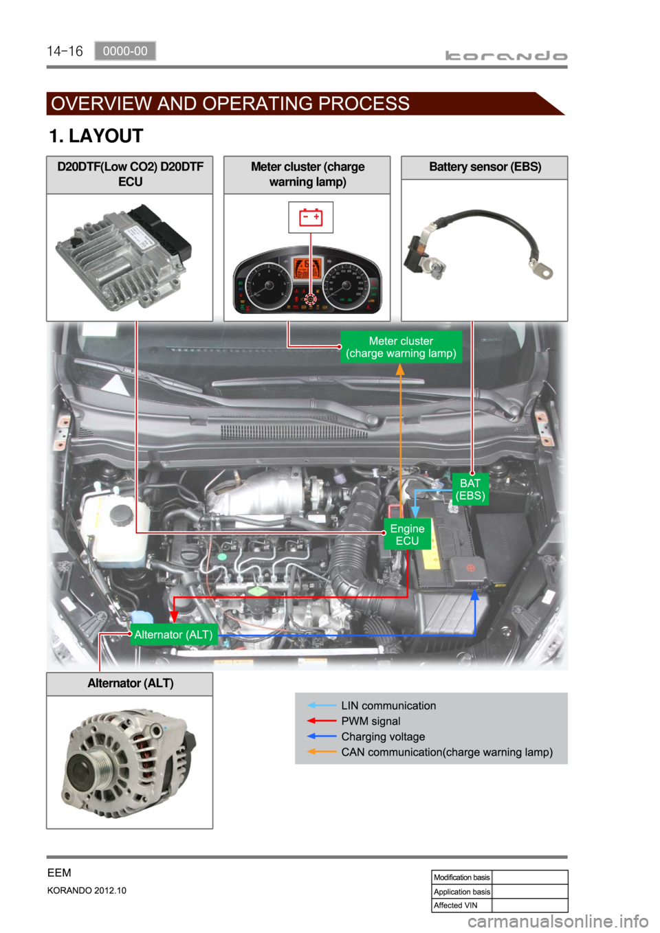
D20DTF(Low CO2) D20DTF
ECUBattery sensor (EBS)
Alternator (ALT)
Meter cluster (charge
warning lamp)
Page 541 of 1082

02-38410-00
1. CAUTIONS WHEN WORKING ON ELECTRICAL UNITS
Disconnect the negative cable from the battery
in advance when working on electrical units. -
If a fuse is blown, replace it with a fuse which
has the correct amperage rating. If you use a
fuse with higher capacity than the
specification, the component can be
damaged or catch fire. -Do not drop or appy excessive impact to
sensors and relays. -
80℃
10 A 15 A
Make sure to turn "OFF" the ignition switch
and other lamp switches before disconnecting
or connecting the negative battery cable.
(Otherwise, semiconductor parts can be
damaged.)
Page 570 of 1082

03-4
2. FUNCTIONS
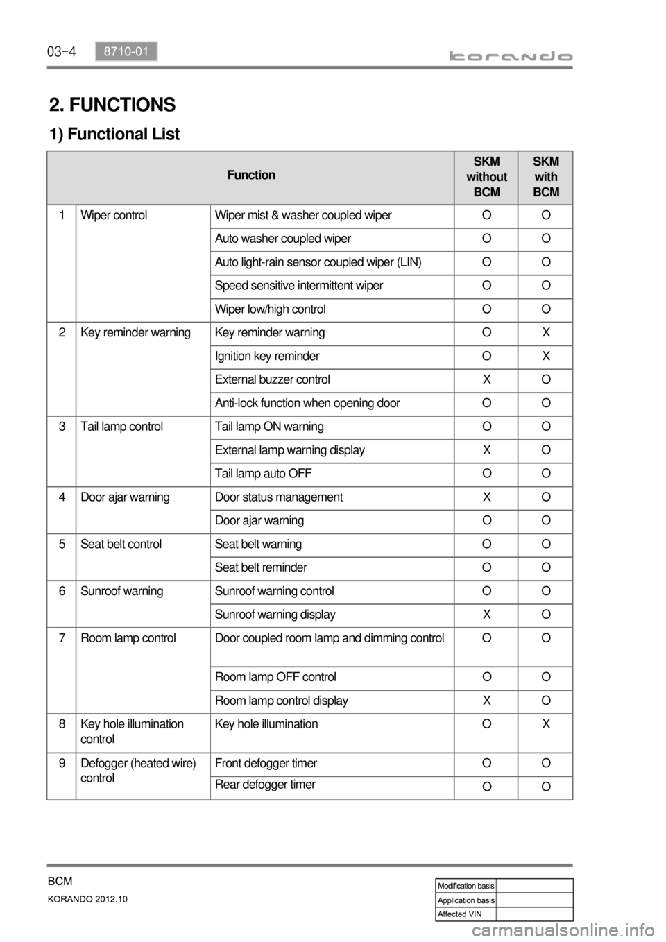
1) Functional List
FunctionSKM
without
BCMSKM
with
BCM
1 Wiper control Wiper mist & washer coupled wiper O O
Auto washer coupled wiper O O
Auto light-rain sensor coupled wiper (LIN) O O
Speed sensitive intermittent wiper O O
Wiper low/high control O O
2 Key reminder warning Key reminder warning O X
Ignition key reminder O X
External buzzer control X O
Anti-lock function when opening door O O
3 Tail lamp control Tail lamp ON warning O O
External lamp warning display X O
Tail lamp auto OFF O O
4 Door ajar warning Door status management X O
Door ajar warning O O
5 Seat belt control Seat belt warning O O
Seat belt reminder O O
6 Sunroof warning Sunroof warning control O O
Sunroof warning display X O
7 Room lamp control Door coupled room lamp and dimming control O O
Room lamp OFF control O O
Room lamp control display X O
8 Key hole illumination
controlKey hole illumination O X
9 Defogger (heated wire)
controlFront defogger timer O O
Rear defogger timer
OO
Page 580 of 1082

03-14
Rain sensor coupled wiper (LIN) ▶
System layout 1.
Data recognition & operation 2.
Data recognition time
The system performs LIN communication regardless of the conditions of wiper and light switch when
the ignition switch is in ON position. If the intermittent/automatic wiper switch is in "AUTO" and the
light switch is in "AUTO" position, the wiper system operates according to the LIN data.
The data received from the rain sensor is recognized for 2 times consecutively.
Operation when recognizing data
No data: wiper low/high relay OFF
Low speed signal: low relay ON (ON for at least one cycle), but high relay OFF
High speed signal: high relay ON (ON for at least one cycle), but low relay OFF
The washer switch signal is overridden during continuous operation of the wiper.
(Washer coupled wiper function is available only during intermittent operation) -
-
Page 581 of 1082

03-158710-01
Power-up reminder wiper ▶
If the intermittent/automatic wiper switch is in "ON" position, the wiper motor does not operate even
when turning the ignition switch to ON from OFF position.
When turning the intermittent/automatic wiper switch to ON from OFF position with IGN ON, the wipers
operate once at low speed initially regardless of the communication with the rain sensor. After that, the
wipers operate once at low speed only when the rain sensor detects
the side fascia panel. 1.
2.
Page 582 of 1082

03-16
Washer coupled wiper in rain sensing mode ▶
When the washer switch signal is received during intermittent operation coupled with rain sensor
with IGN ON and intermittent/automatic washer switch operation, the wipers operate in washer
coupled mode regardless of the communication with the rain sensor. However, if the washer switch
signal is received the washer relay is activated and wiper relay remains activated, when the data
coupled with rain sensor indicates continuous wiper operation.
Even though the wiping system is in washer coupled wiper mode, the operating data are sent to rain
sensor. 1.
2.
Sensitivity adjustment (instant wiping) ▶
When the wiping speed control switch is turned to "FAST" with IGN2 ON, intermittent/automatic wiper
switch in "ON" position and wiper motor stop (parking position), the wiper motor operates one cycle at
low speed.
(only when the rain sensor detects raindrops)
If the wiping speed control switch is changed more than 2 stages within 2 seconds, the wiper motor
operates only one cycle. 1.
*
Page 583 of 1082

03-178710-01
Processing method for abnormal wiper parking signal ▶
The wiper system sends continuously the signal for current status when the wiper parking terminal is
shorted to ground with IGN2 ON and intermittent wiper switch in "ON" position.
The wiper motor runs only when the rain sensor requires the wiper operation. 1.*
When the parking terminal is shorted to power with IGN2 ON and intermittent wiper switch in "ON"
position, the wiper system sends the signal for current wiping status for 2 seconds. After that, it sends
the current signal for parking status continuously.
The wiper motor runs only when the rain sensor requires the wiper operation. 2.*