sensor SSANGYONG KORANDO 2012 Service Manual
[x] Cancel search | Manufacturer: SSANGYONG, Model Year: 2012, Model line: KORANDO, Model: SSANGYONG KORANDO 2012Pages: 1082, PDF Size: 96.1 MB
Page 819 of 1082
01-90000-00
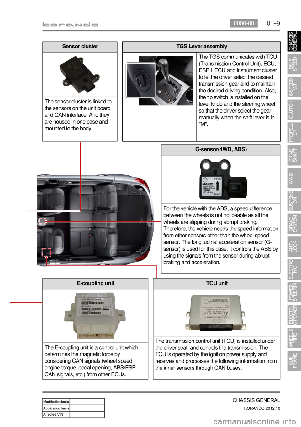
G-sensor(4WD, ABS)
For the vehicle with the ABS, a speed difference
between the wheels is not noticeable as all the
wheels are slipping during abrupt braking.
Therefore, the vehicle needs the speed information
from other sensors other than the wheel speed
sensor. The longitudinal acceleration sensor (G-
sensor) is used for this case. It controls the ABS by
using the signals from the sensor during abrupt
braking and acceleration.
TCU unit
The transmission control unit (TCU) is installed under
the driver seat, and controls the transmission. The
TCU is operated by the ignition power supply and
receives and processes the following information from
the inner sensors through CAN buses.E-coupling unit
The E-coupling unit is a control unit which
determines the magnetic force by
considering CAN signals (wheel speed,
engine torque, pedal opening, ABS/ESP
CAN signals, etc.) from other ECUs.
TGS Lever assembly
The TGS communicates with TCU
(Transmission Control Unit), ECU,
ESP HECU and instrument cluster
to let the driver select the desired
transmission gear and to maintain
the desired driving condition. Also,
the tip switch is installed on the
lever knob and the steering wheel
so that the driver select the gear
manually when the shift lever is in
"M".Sensor cluster
The sensor cluster is linked to
the sensors on the unit board
and CAN interface. And they
are housed in one case and
mounted to the body.
Page 829 of 1082
01-190000-00
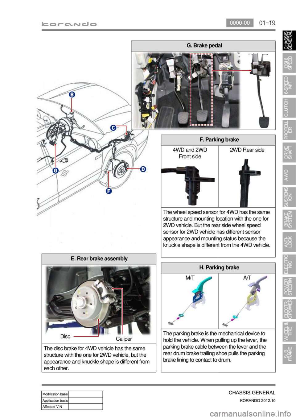
H. Parking brake
M/T A/T
The parking brake is the mechanical device to
hold the vehicle. When pulling up the lever, the
parking brake cable between the lever and the
rear drum brake trailing shoe pulls the parking
brake lining to contact to drum.
E. Rear brake assembly
The disc brake for 4WD vehicle has the same
structure with the one for 2WD vehicle, but the
appearance and knuckle shape is different from
each other.
Caliper
G. Brake pedal
Disc
F. Parking brake
4WD and 2WD
Front side2WD Rear side
The wheel speed sensor for 4WD has the same
structure and mounting location with the one for
2WD vehicle. But the rear side wheel speed
sensor for 2WD vehicle has different sensor
appearance and mounting status because the
knuckle shape is different from the 4WD vehicle.
Page 831 of 1082

01-210000-00
ECU
The ECU controls the electric
power steering system
depending on the driving
conditions, based on the
signals from the torque and
angle sensor.
2) EPS (Electric Power Steering)
Fuse
The vehicle with EPS has
EPS fuse (80A) mounted to
the positive (+) terminal of the
battery, and this fuse supplies
power to the EPS unit
directly..
Steering gear box assembly
When the driver turns the steering wheel, a torque is generated and the torque sensor and the steering
angle sensor in the EPS system detect the rotation of the steering column to run the electric motor. At
this time, the worm gear connected to the motor drives the helical gear mounted to the steering column
to generate the assist torque for the steering column. This allows the driver to operate the steering
wheel easier.
ECU
Tie rod end
Tie rod end Gear boxSteering cylinder
Steering wheel assembly
BLAC motor
Lower
shaft Column
shaft
Colum shaft assembly
The column shaft assembly consists
of BLAC motor, ECU, torque and
angle sensors. The electric power
steering (EPS) system uses the
electric motor to assist the steering
force. It functions independently
regardless of whether the engine is
running or not, unlike the existing
hydraulic power steering.
The lower shafts functions in the
same way as the hydraulic type.
Page 837 of 1082
02-33680-01
1. GENERAL INFORMATION
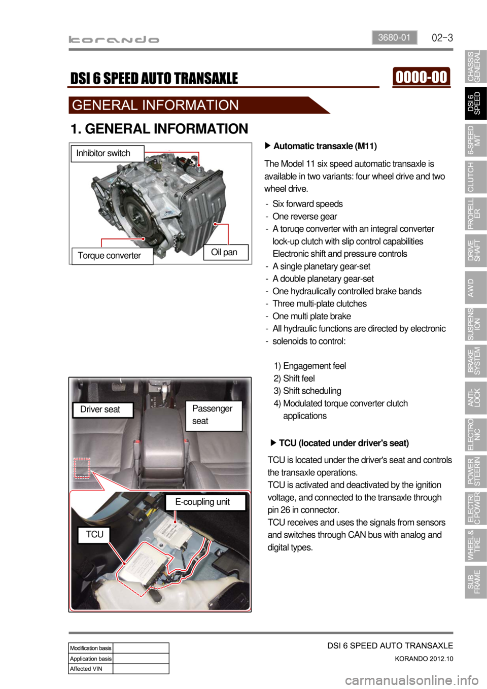
Automatic transaxle (M11) ▶
The Model 11 six speed automatic transaxle is
available in two variants: four wheel drive and two
wheel drive.
Six forward speeds
One reverse gear
A toruqe converter with an integral converter
lock-up clutch with slip control capabilities
Electronic shift and pressure controls
A single planetary gear-set
A double planetary gear-set
One hydraulically controlled brake bands
Three multi-plate clutches
One multi plate brake
All hydraulic functions are directed by electronic
solenoids to control: -
-
-
-
-
-
-
-
-
-
Engagement feel
Shift feel
Shift scheduling
Modulated torque converter clutch
applications 1)
2)
3)
4) Inhibitor switch
Oil pan
Torque converter
TCU (located under driver's seat) ▶
TCU is located under the driver's seat and controls
the transaxle operations.
TCU is activated and deactivated by the ignition
voltage, and connected to the transaxle through
pin 26 in connector.
TCU receives and uses the signals from sensors
and switches through CAN bus with analog and
digital types. Driver seat
E-coupling unit
TCU
Passenger
seat
Page 839 of 1082
02-53680-01
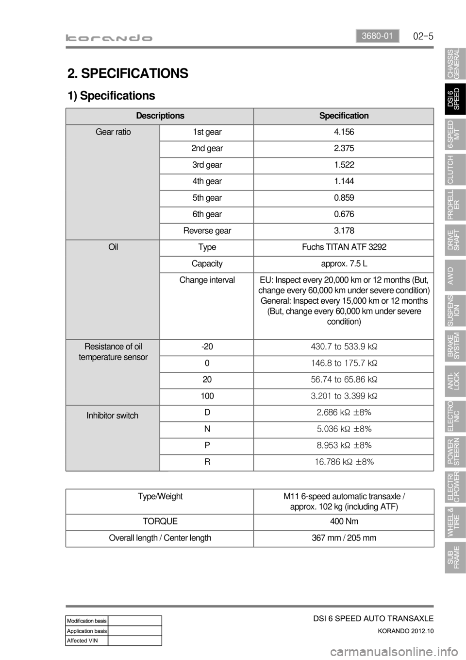
2. SPECIFICATIONS
1) Specifications
Type/Weight M11 6-speed automatic transaxle /
approx. 102 kg (including ATF)
TORQUE 400 Nm
Overall length / Center length 367 mm / 205 mm
Descriptions Specification
Gear ratio 1st gear 4.156
2nd gear 2.375
3rd gear 1.522
4th gear 1.144
5th gear 0.859
6th gear 0.676
Reverse gear 3.178
Oil Type Fuchs TITAN ATF 3292
Capacity approx. 7.5 L
Change interval EU: Inspect every 20,000 km or 12 months (But,
change every 60,000 km under severe condition)
General: Inspect every 15,000 km or 12 months
(But, change every 60,000 km under severe
condition)
Resistance of oil
temperature sensor-20430.7 to 533.9 kΩ
0146.8 to 175.7 kΩ
2056.74 to 65.86 kΩ
1003.201 to 3.399 kΩ
D2.686 kΩ ±8%
N5.036 kΩ ±8%
P8.953 kΩ ±8%
R16.786 kΩ ±8%
Inhibitor switch
Page 842 of 1082
02-8
1. OVERVIEW
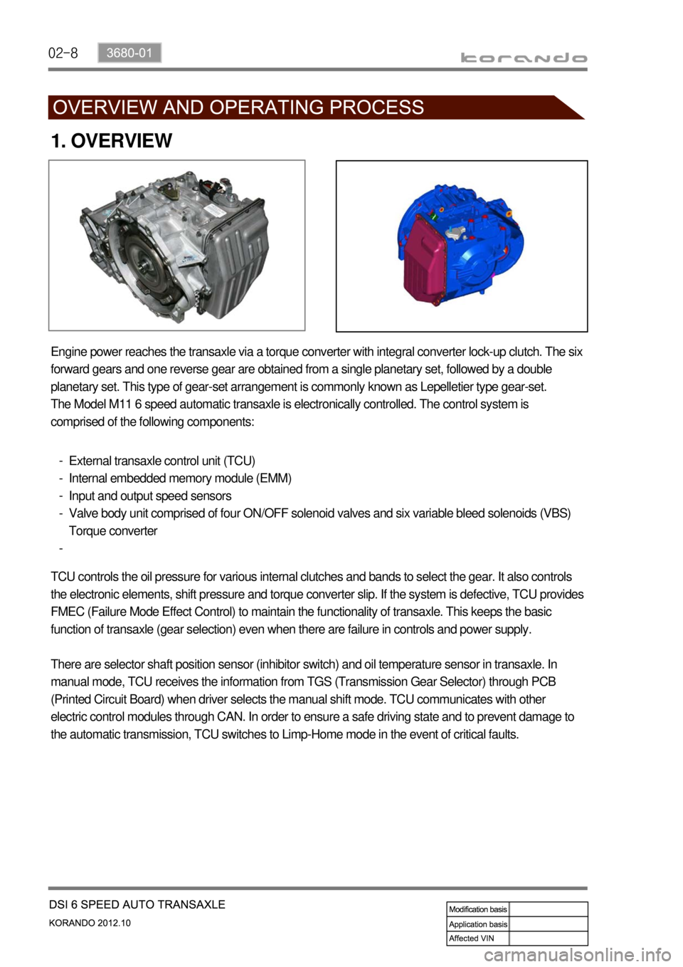
Engine power reaches the transaxle via a torque converter with integral converter lock-up clutch. The six
forward gears and one reverse gear are obtained from a single planetary set, followed by a double
planetary set. This type of gear-set arrangement is commonly known as Lepelletier type gear-set.
The Model M11 6 speed automatic transaxle is electronically controlled. The control system is
comprised of the following components:
External transaxle control unit (TCU)
Internal embedded memory module (EMM)
Input and output speed sensors
Valve body unit comprised of four ON/OFF solenoid valves and six variable bleed solenoids (VBS)
Torque converter -
-
-
-
-
TCU controls the oil pressure for various internal clutches and bands to select the gear. It also controls
the electronic elements, shift pressure and torque converter slip. If the system is defective, TCU provides
FMEC (Failure Mode Effect Control) to maintain the functionality of transaxle. This keeps the basic
function of transaxle (gear selection) even when there are failure in controls and power supply.
There are selector shaft position sensor (inhibitor switch) and oil temperature sensor in transaxle. In
manual mode, TCU receives the information from TGS (Transmission Gear Selector) through PCB
(Printed Circuit Board) when driver selects the manual shift mode. TCU communicates with other
electric control modules through CAN. In order to ensure a safe driving state and to prevent damage to
the automatic transmission, TCU switches to Limp-Home mode in the event of critical faults.
Page 844 of 1082

02-10
2) Transaxle Cooling
The transaxle cooling system ensures rapid warm-up and constant operating temperature resulting in
reduced fuel consumption and refined shift quality.
It also includes a cooler by-pass within the hydraulic system to allow sufficient lubrication to the transaxle
drivetrain in the event of a blockage in the transaxle cooler.
3) Shift Strategy
Gear Change ▶
Transaxle gear change is controlled by the
TCU. The TCU receives inputs from various
engine and vehicle sensors to select shift
schedules and to control the shift feel and
torque converter clutch (TCC) operation at each
gear change.
Coast down ▶
Coast down down shifts occur at 0% pedal
when the vehicle is coasting down to a stop.
Torque Demand ▶
Torque demand down shifts occur
(automatically) when the driver demand for
torque is greater than the engine can provide at
that gear ratio. If applied, the transaxle will
disengage the TCC to provide added
acceleration.
Page 848 of 1082
02-14
5. TRANSAXLE ELECTRONIC CONTROL SYSTEM
1) General Information
The transmission control unit (TCU) and its input/output network control the following transmission
operations:
Shift timing
Line pressure
Clutch pressure (shift feel)
Torque converter clutch -
-
-
-
also uses these signals when determining transaxle operating strategy. Using all of these input signals,
the TCU can determine when the time and conditions are right for a shift, or when to apply or release the
torque converter clutch. It will also determine the pressure needed to optimise shift feel. To accomplish
this, the TCU operates six variable bleed control solenoids and four on/off solenoids to control transaxle
operation.
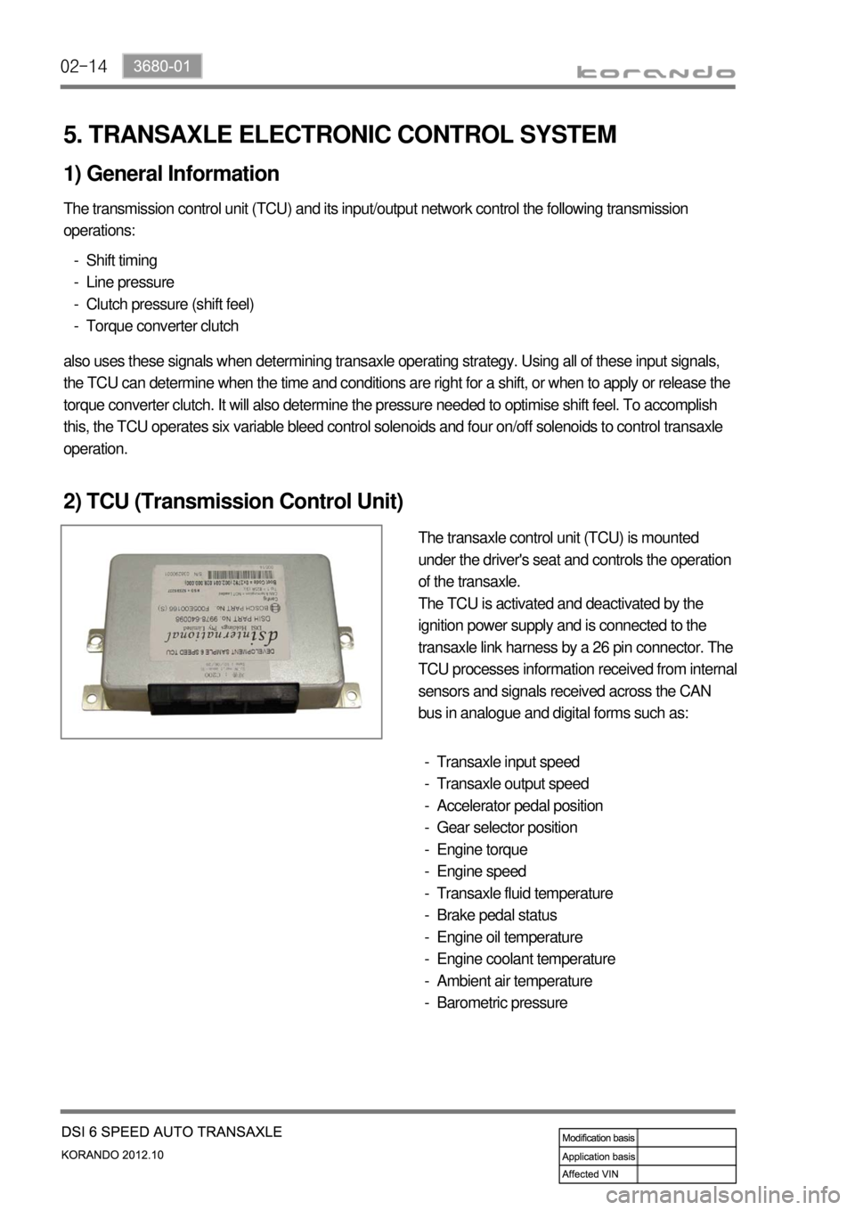
2) TCU (Transmission Control Unit)
The transaxle control unit (TCU) is mounted
under the driver's seat and controls the operation
of the transaxle.
The TCU is activated and deactivated by the
ignition power supply and is connected to the
transaxle link harness by a 26 pin connector. The
TCU processes information received from internal
sensors and signals received across the CAN
bus in analogue and digital forms such as:
Transaxle input speed
Transaxle output speed
Accelerator pedal position
Gear selector position
Engine torque
Engine speed
Transaxle fluid temperature
Brake pedal status
Engine oil temperature
Engine coolant temperature
Ambient air temperature
Barometric pressure -
-
-
-
-
-
-
-
-
-
-
-
Page 863 of 1082
03-33660-01
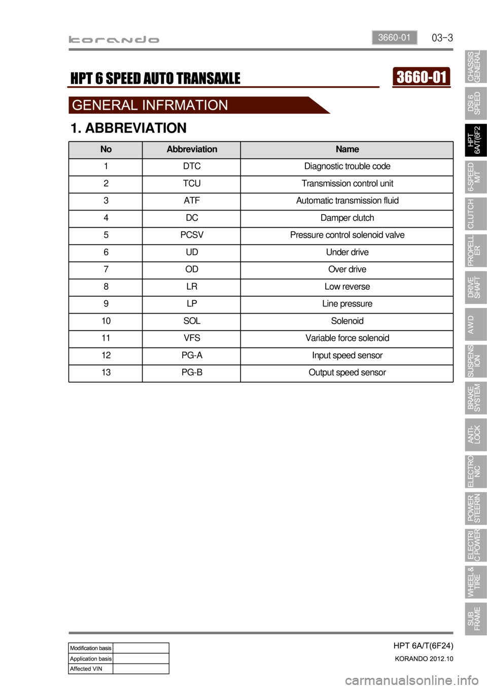
1. ABBREVIATION
No Abbreviation Name
1 DTC Diagnostic trouble code
2 TCU Transmission control unit
3 ATF Automatic transmission fluid
4 DC Damper clutch
5 PCSV Pressure control solenoid valve
6 UD Under drive
7OD Over drive
8 LR Low reverse
9 LP Line pressure
10 SOL Solenoid
11 VFS Variable force solenoid
12 PG-A Input speed sensor
13 PG-B Output speed sensor
Page 864 of 1082
03-4
2. GENERAL INFORMATION
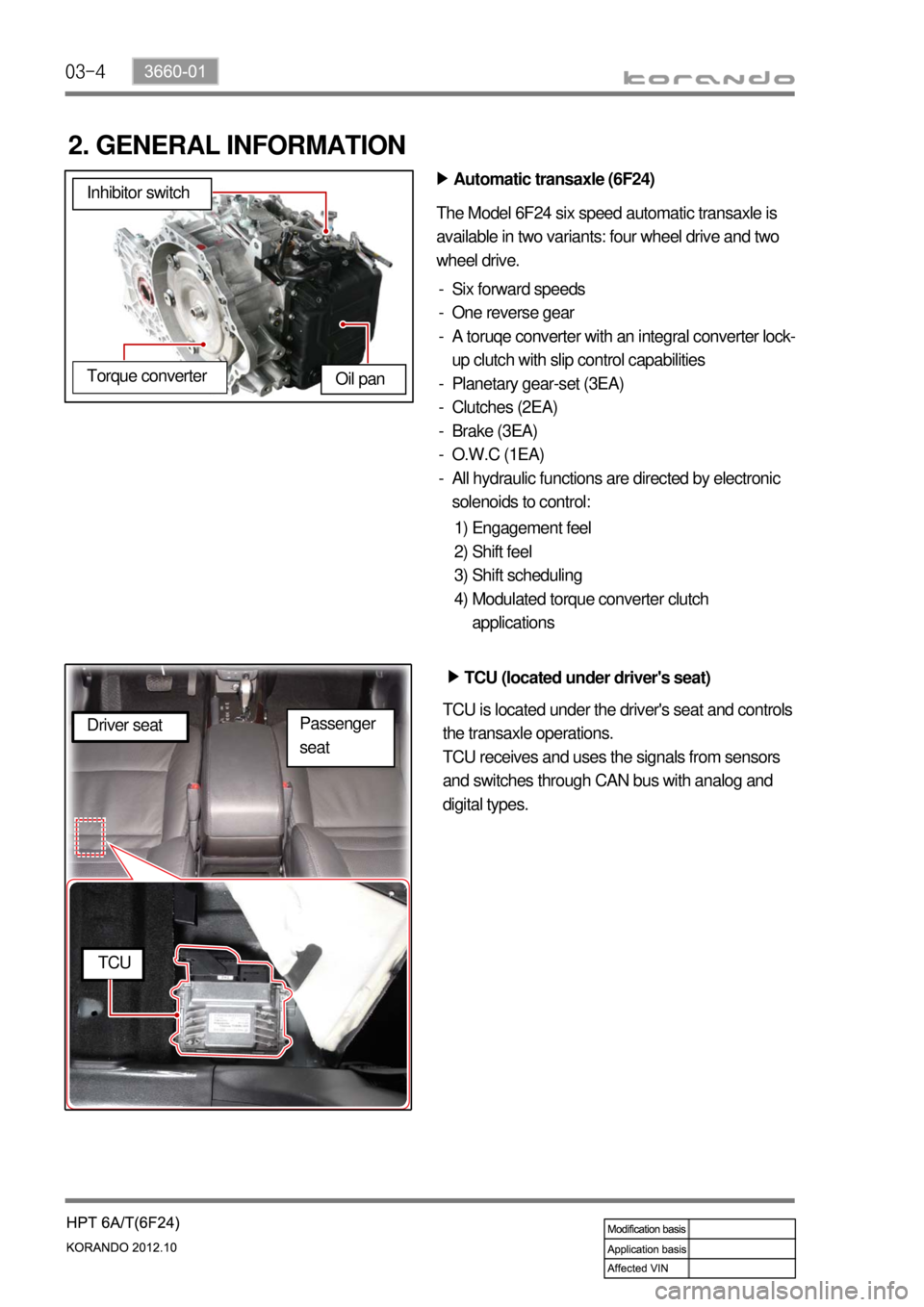
Automatic transaxle (6F24) ▶
The Model 6F24 six speed automatic transaxle is
available in two variants: four wheel drive and two
wheel drive.
Six forward speeds
One reverse gear
A toruqe converter with an integral converter lock-
up clutch with slip control capabilities
Planetary gear-set (3EA)
Clutches (2EA)
Brake (3EA)
O.W.C (1EA)
All hydraulic functions are directed by electronic
solenoids to control: -
-
-
-
-
-
-
-
Engagement feel
Shift feel
Shift scheduling
Modulated torque converter clutch
applications 1)
2)
3)
4) Inhibitor switch
Oil pan
Torque converter
TCU (located under driver's seat) ▶
TCU is located under the driver's seat and controls
the transaxle operations.
TCU receives and uses the signals from sensors
and switches through CAN bus with analog and
digital types. Driver seat
TCU
Passenger
seat