change time SSANGYONG KORANDO 2012 User Guide
[x] Cancel search | Manufacturer: SSANGYONG, Model Year: 2012, Model line: KORANDO, Model: SSANGYONG KORANDO 2012Pages: 1082, PDF Size: 96.1 MB
Page 642 of 1082

04-8
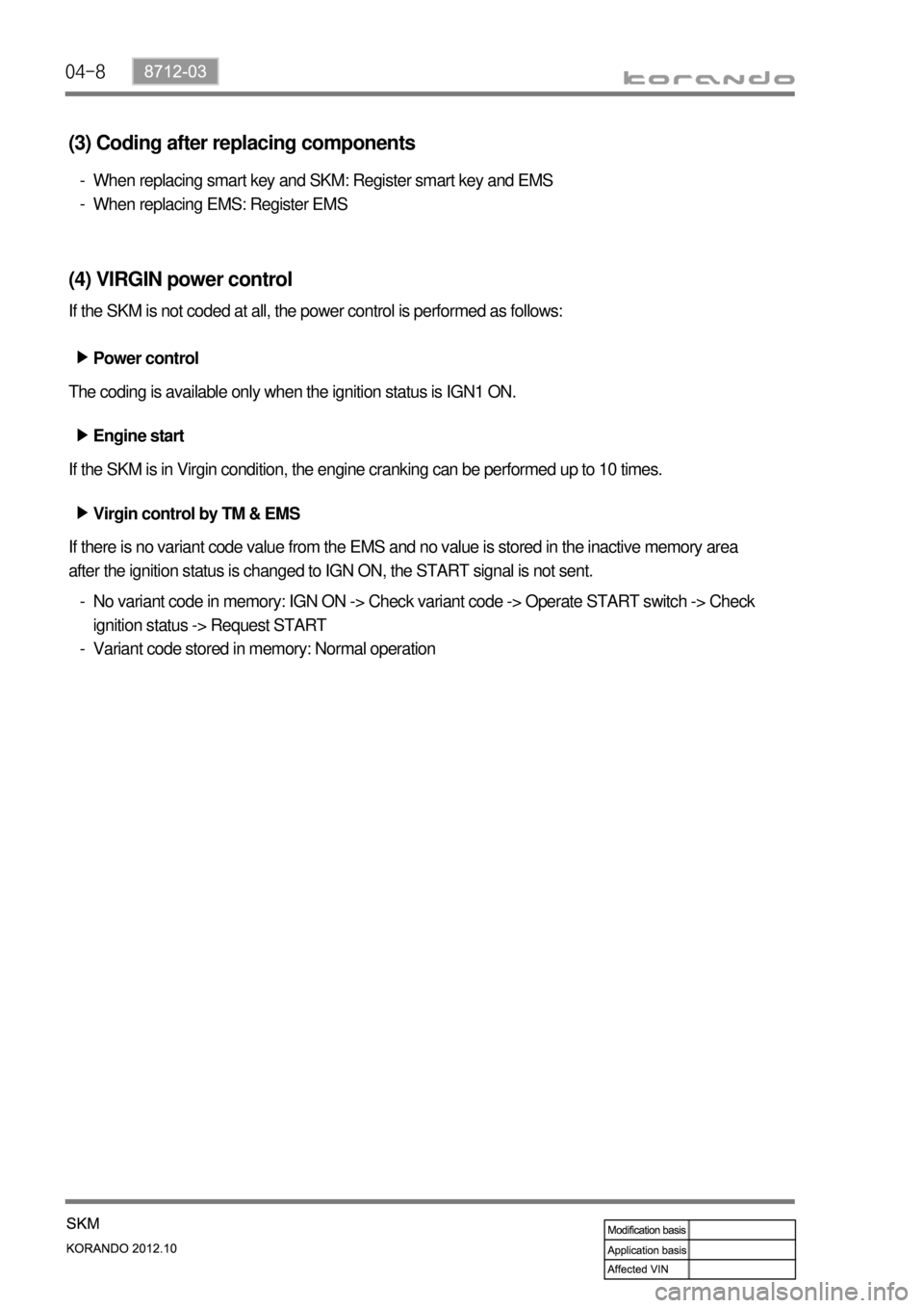
(3) Coding after replacing components
When replacing smart key and SKM: Register smart key and EMS
When replacing EMS: Register EMS -
-
(4) VIRGIN power control
If the SKM is not coded at all, the power control is performed as follows:
Virgin control by TM & EMS ▶
If there is no variant code value from the EMS and no value is stored in the inactive memory area
after the ignition status is changed to IGN ON, the START signal is not sent.Power control ▶
The coding is available only when the ignition status is IGN1 ON.
Engine start ▶
If the SKM is in Virgin condition, the engine cranking can be performed up to 10 times.
No variant code in memory: IGN ON -> Check variant code -> Operate START switch -> Check
ignition status -> Request START
Variant code stored in memory: Normal operation -
-
Page 653 of 1082

04-198712-03
4) Smart Key Verification Time Control
(1) Pre-verification timer
When the operation signal from the START switch is received, the START & power control functions can
be performed without smart key verification.
(2) Immobilizer verification timer
The immobilizer verification status indicates that it is possible to respond to the request message sent
from the EMS to deactivate the immobilizer. The SKM verified a smart key and the engine can be
started.
The 30-second immobilizer verification time is started when:
the ignition status is changed to IGN by the START switch while the pre-verification timer is activated.
the ignition status is changed to IGN by the smart key verification while the pre-verification timer is
stopped; the SKM verified a smart key by the brake switch signal while the immobilizer verification
timer is stopped or the ignition status is IGN ON.
the SKM verified a smart key successfully if the immobilizer verification timer is stopped with IGN
ON/immobilizer verification /brake switch ON. -
-
-
Condition SKM operation
- when door closed signal is input with - B+ or ACC ON
- when brake is applied with - B+ or ACC ON
- when START switch is operated with - B+
- when smart key is inserted into slot & brake switch is
operated or START switch is operated with - B+Once the vehicle interior verification
is completed, 30 sec. pre-verification
timer is started
when the ignition is turned OFF with IGN ON and engine
running 30 sec. pre-verification timer is
started without re-verification
Timer deactivation conditions: after 30 sec. has passed, IGN ON, Outside door handle switch ON,
entering theft deterrent mode when door condition is changed
IGN1 OFF
30 sec. has passed after immobilizer verification
Any door is opened and then closed when all doors are closed & smart key out
When the engine starts to run, the immobilizer verification status is determined, and the immobilizer will
not be deactivated until the ignition status is changed to IGN/ACC/OFF.
The immobilizer is not deactivated when the key out warning condition is met while the engine is
running. (when the RND is received by the EMS reset while the engine is running)
When attempting to start the engine without immobilizer verification, the system performs smart key
verification procedures, and sends the engine start request to EMS only when the verification result is
normal. -
-
-
*
*
*Entry conditions ▶
Deactivation condition ▶
Page 655 of 1082

04-218712-03
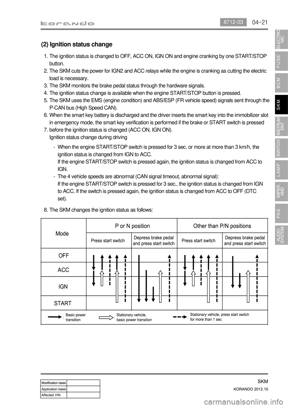
(2) Ignition status change
The ignition status is changed to OFF, ACC ON, IGN ON and engine cranking by one START/STOP
button.
The SKM cuts the power for IGN2 and ACC relays while the engine is cranking as cutting the electric
load is necessary.
The SKM monitors the brake pedal status through the hardware signals.
The ignition status change is available when the engine START/STOP button is pressed.
The SKM uses the EMS (engine condition) and ABS/ESP (FR vehicle speed) signals sent through the
P-CAN bus (High Speed CAN).
When the smart key battery is discharged and the driver inserts the smart key into the immobilizer slot
in emergency mode, the smart key verification is performed if the brake or START switch is pressed
before the ignition status is changed (ACC ON, IGN ON).
Ignition status change during driving 1.
2.
3.
4.
5.
6.
7.
When the engine START/STOP switch is pressed for 3 sec. or more at more than 3 km/h, the
ignition status is changed from IGN to ACC.
If the engine START/STOP switch is pressed again, the ignition status is changed from ACC to
IGN.
The 4 vehicle speeds are abnormal (CAN signal timeout, abnormal signal):
If the engine START/STOP switch is pressed for 3 sec., the ignition status is changed from IGN
to ACC. If the switch is pressed again, the ignition status is changed from ACC to OFF (DTC
set). -
-
The SKM changes the ignition status as follows: 8.
Page 657 of 1082

04-238712-03
(4) Engine stop
When the START button is pressed at the vehicle speed of 3 km/h or less, the SKM turns off the IGN
relay to stop the engine.
When the vehicle speed is 3 km/h or more or no speed signal is input, the SKM performs the
following functions: 1.
2.
When the START switch is pressed for 3 sec. or more at more than 3 km/h, the ignition status is
changed from IGN to ACC.
If the switch is pressed again, the ignition status is changed from ACC to IGN.
When the START switch is pressed for 3 sec. or more with no vehicle speed signal (CAN signal
timeout, abnormal signal), the ignition status is changed from IGN to ACC. If the switch is pressed
again, the ignition status is changed from ACC to OFF. -
-
When the START button is pressed and held with IGN ON, the ignition status is changed to OFF.
When the START button is pressed briefly, the ignition status is changed to ACC ON. 3.
(5) ACC ON/Power OFF
The SKM changes the ignition status to OFF from ACC ON when:
the engine START/STOP button is pressed with the brake pedal released after the ignition status is
changed from IGN ON to ACC ON.
the REKES LOCK or passive LOCK is operated with ACC ON.
the BCM sends the driver's door open signal.
12 minutes have passed with ACC ON. 1.
2.
3.
4.Except brake switch signal input
For the vehicles with A/T, when the START switch is pressed for 10 sec. or more, the ignition
status is changed to IGN ON and the engine start request signal is sent regardless of the brake
signal, provided that the initial ignition status is ACC ON and the gear selector lever is in P or N
position. *-
Page 665 of 1082

04-318712-03
(8) Brake not working alert
The SKM sends the brake not working alert signal for 10 sec. every time the ignition status is changed
after the 1st cycle (OFF-ACC-IGN-ACC-OFF) while the brake is not operated.
when the brake pedal is depressed, the system is reset and alert deactivation signal is sent.
when the 10 min. timer is terminated -
-
(9) Clutch not working alert
The SKM sends the clutch not working alert signal for 10 sec. every time the ignition status is changed
after the 1st cycle (OFF-ACC-IGN-ACC-OFF)
while the clutch is not operated.
when the clutch pedal is depressed, the system is reset and alert deactivation signal is sent.
when the 10 min. timer is terminated -
-
(10) Smart key slot detection alert
The SKM sends the smart key slot detection alert signal for 10 sec. when a smart key inserted into
the slot is detected with IGN OFF and the driver's door open. -
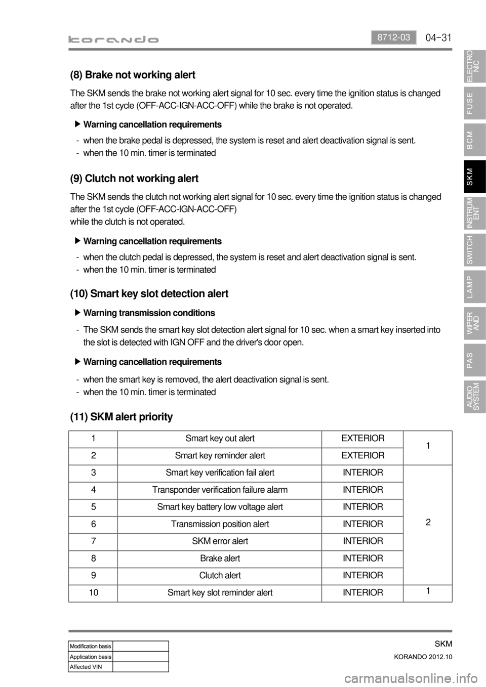
(11) SKM alert priority
1 Smart key out alert EXTERIOR
1
2 Smart key reminder alert EXTERIOR
3 Smart key verification fail alert INTERIOR
2 4 Transponder verification failure alarm INTERIOR
5 Smart key battery low voltage alert INTERIOR
6 Transmission position alert INTERIOR
7 SKM error alert INTERIOR
8 Brake alert INTERIOR
9 Clutch alert INTERIOR
10 Smart key slot reminder alert INTERIOR1
Warning cancellation requirements ▶
Warning cancellation requirements ▶
Warning transmission conditions ▶
Warning cancellation requirements ▶
when the smart key is removed, the alert deactivation signal is sent.
when the 10 min. timer is terminated -
-
Page 687 of 1082

05-24
4) Display Sequence
Display sequence for STD main LCD & SVC DOT LCD ▶
Operating time of Trip
switchFunction
Below 1 second
(60 to 980 ms)STD Mode change
(ODO → TRIP A → TRIP B → DTE → AFC → IFC →
ILLUMINATION → OUT TEMP)
SVC Mode change
(TRIP A → TRIP B → DTE → AFC → IFC →
ILLUMINATION → OUT TEMP)
Over 1 seconds Reset function (Trip A, B, AFC)
<004f007000930093009c0094009000950088009b0090009600950047004f005d0047009b00960047005800470093008c009d008c0093005000530047009c00950090009b00470096008d00470096009c009b009a0090008b008c0047009b008c0094009700
8c00990088009b009c0099008c0047004f0b45004702e90047>℉))
Over 3 seconds - Ready Mode change
(Illumination → OUT TEMP → ODO)
If the Trip/Reset switch is not pressed within 3 seconds after getting into the illumination mode and the
ambient air temperature mode, the LCD changes to next mode.
The factory-setting mode is DTE (Distance To Empty) mode. *
*
Page 736 of 1082

06-258510-00
SVC class instrument cluster
TRIP A TRIP B
(3) Trip switch
Whenever pressing this button, the information is displayed in the following order: Odometer, Trip A, Trip
B, Distance to empty, Average fuel consumption, Instant fuel consumption, Illumination level, Ambient air
temperature (for STD); Trip A, Trip B, Distance to empty, Average fuel consumption, Instant fuel
consumption, Illumination level, Ambient air temperature (for SVC). Press and hold (for more than 1 sec)
this button to initialize (reset) Trip A/Trip B and average fuel consumption, adjust illumination level or
change the unit of temperature.
Description ▶
The factory setting is DTE mode. ※ Display
Mode
SwitchDetecting
timeFunction
Briefly
and holdBelow 1
second
(60 to
980 ms)STD- Mode change
(Odo→Trip A→Trip B→DTE
<00470047004702e70068009d008c00990088008e008c0047008d009c008c00930047008a00960095009a009c00940097009b00900096009502e700700095009a009b00880095009b0047008d009c008c00930047008a00960095009a009c00940097009b00
9000960095>
→Illumination level→Ambient air temperature)
SVC- Mode change
(Trip A→Trip B→DTE→Average fuel consumption
→Instant fuel consumption→Illumination level
→Ambient air temperature)
Press
and holdOver 1
seconds- Reset
(Trip A, B, average fuel consumption)
- Change
<004700470047004f007000930093009c0094009000950088009b00900096009500470093008c009d008c00930047004f005d0047009b009600470058005000530047009b008c00940097008c00990088009b009c0099008c0047009c00950090009b004700
4f0b4502e90d9100500050>
Not
pressOver 3
seconds- Mode change
<004700470047004f007000930093009c0094009000950088009b00900096009500470093008c009d008c009302e70068009400890090008c0095009b00470088009000990047009b008c00940097008c00990088009b009c0099008c02e70076008b009600
50>
STD class instrument cluster
TRIP A TRIP B
Page 763 of 1082

07-10
(5) Auto light (LIN)
The auto light sensor unit is installed to the back side of the ECM mirror located upper center of the
windshield, and detects the illuminance change. The BCM communicates with the auto light sensor
when the ignition is turned on, and turns on or off the tail lamp and headlamp automatically according to
the signals from the sensor when the multifunction switch is set to AUTO light.
The BCM communicates with the rain sensor even if the multifunction switch is in tail lamp.
Auto light switch Automatic light sensor unit
(6) Side repeater lamp
Side repeater lamp
The side repeater lamp is operated by the BCM when the BCM receives a signal from the multifunction
switch.
The BCM cycles the side repeater lamp and buzzer (ON/OFF) 75 times per minute.
The side repeater lamp operates only when IGN1 is ON.
If the side repeater lamp fails while it is illuminated, the BCM cycles the lamp and buzzer 100 times per
minute.
The lamp automatically flashes 3 times when the multifunction switch is turned on. If the switch is turned
off
during this operation, the lamp flashes 3 times and then goes off.
If the switch is turned off and then on during the 3 times of automatic flashing, the lamp flashes 3 more
times.
Page 772 of 1082

08-6
3) Fluidic Washer Nozzle
This vehicle has the fluidic washer nozzle, which is designed to use fluid movement occurring in the
washer fluid spraying process.
When installing the washer nozzle, make sure that the mounting surface is clean and free of dirt or
debris, since the water may come into the engine compartment in accordance with a seamless
contact condition between the mounting surface of the nozzle and the curved surface of the engine
hood. *
The inside of the nozzle is designed in a fan shape to change the spray direction continuously based on
the time the fluid is sprayed. Refer to the figure below.
The spray direction is changed by means of the whirlwind and back flow generated while the washer
fluid is passing through the nozzle.Washer fluid inlet portSpray passage Counter-currentPassageWasher fluid outlet port
Whirlwind
Washer nozzle
Page 901 of 1082

04-50000-00
1. OVERVIEW
The hydraulic clutch transmits the force required to operate the clutch pedal to the concentric slave
cylinder fitted to the clutch housing as a hydraulic pressure.
(The hydraulic pressure is transmitted in the following order: Clutch pedal - Clutch master cylinder -
Clutch pipe - Clutch damper - Clutch pipe and hose - Concentric slave cylinder - Pressure plate -
Flywheel.)
If a driver depress the clutch pedal, the hydraulic pressure is generated in the master cylinder. It is
transmitted to the concentric slave cylinder through the pipe, resulting in the cylinder being forced out. At
this time, the clutch disc is forced against the cylinder by pushing the cover. This, in turn, remove the
flywheel from the pressure plate. As a consequence, the power from the engine will be cut off and the
gear change can be carried out.