fuel pressure SSANGYONG KORANDO 2012 Owner's Manual
[x] Cancel search | Manufacturer: SSANGYONG, Model Year: 2012, Model line: KORANDO, Model: SSANGYONG KORANDO 2012Pages: 1082, PDF Size: 96.1 MB
Page 163 of 1082
03-28
The engine ECU calculates the accelerator pedal based on the input signals from various sensors, and
controls the overall operation of the vehicle.
The ECU receives the signals from various sensor through data line, and performs effective air-fuel ratio
control based on these signals.
The crankshaft speed (position) sensor measures the engine speed, and the camshaft speed (position)
sensor determines the order of injections, and the ECU detects the amount of the accelerator pedal
depressed (driver's will) by receiving the electrical signals from the accelerator pedal sensor.
The mass air flow sensor detects the volume of intake air and sends the value to the ECU.
The major function of the ECU is controlling air-fuel ratio to reduce the emission level (EGR valve control)
by detecting instantaneous air flow change with the signals from the mass air flow sensor.
Also, the ECU uses the signals from the coolant temperature & air temperature sensors, booster pressure
sensor, atmospheric pressure sensor to: a) determine injection starting point and set value for pilot
injection, and b) deal with various operations and variable conditions.
Page 168 of 1082
04-50000-00
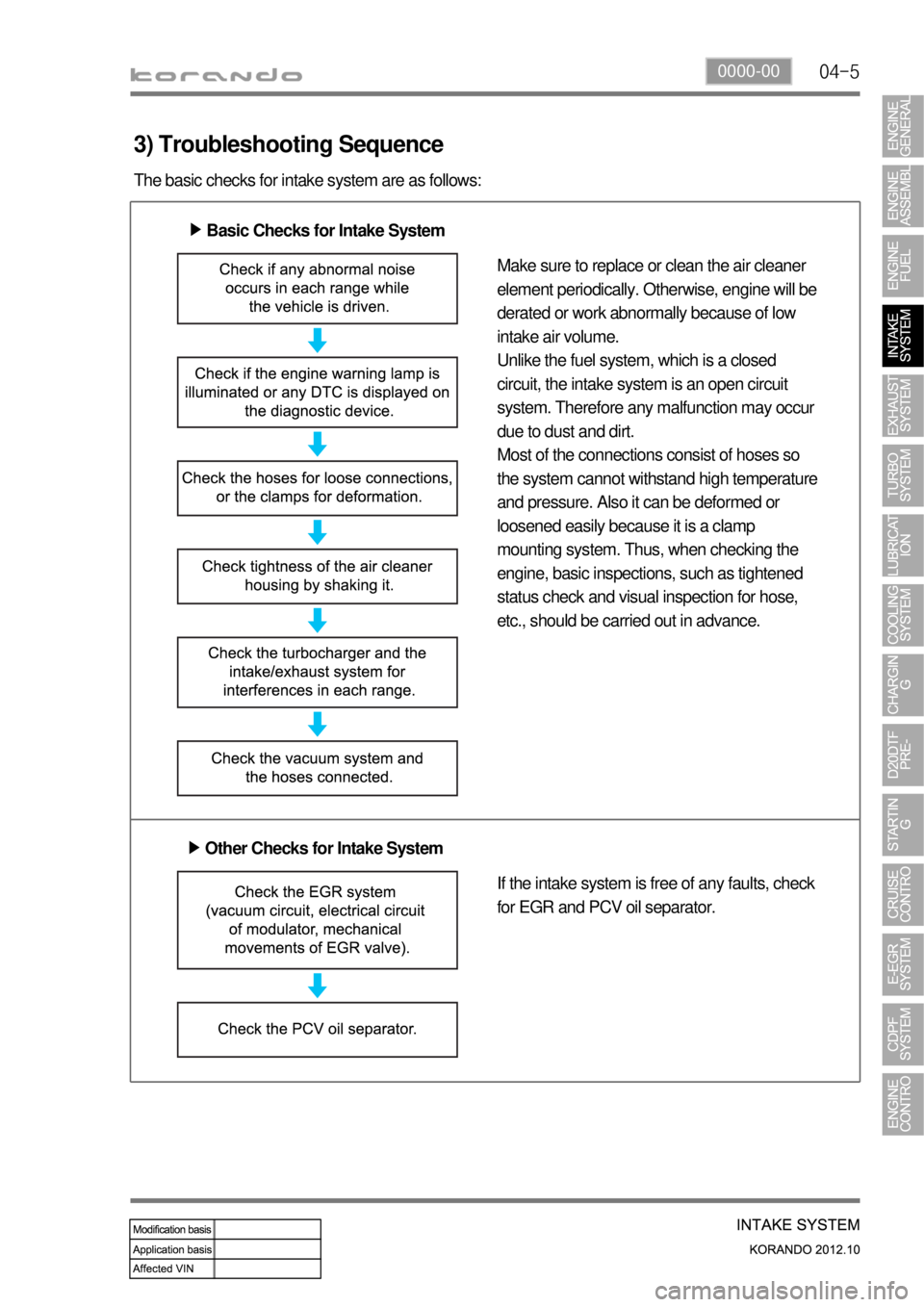
3) Troubleshooting Sequence
The basic checks for intake system are as follows:
Basic Checks for Intake System ▶
Make sure to replace or clean the air cleaner
element periodically. Otherwise, engine will be
derated or work abnormally because of low
intake air volume.
Unlike the fuel system, which is a closed
circuit, the intake system is an open circuit
system. Therefore any malfunction may occur
due to dust and dirt.
Most of the connections consist of hoses so
the system cannot withstand high temperature
and pressure. Also it can be deformed or
loosened easily because it is a clamp
mounting system. Thus, when checking the
engine, basic inspections, such as tightened
status check and visual inspection for hose,
etc., should be carried out in advance.
Other Checks for Intake System ▶
If the intake system is free of any faults, check
for EGR and PCV oil separator.
Page 174 of 1082

04-110000-00
Load Engine speed Swirl
valveAmount of
swirlRemarks
Low speed,
Low loadbelow 3,000 rpm Closed HeavyIncreased EGR ratio, better air-fuel
mixture (reduce exhaust gas)
High speed,
High loadover 3,000 rpm Open LightIncrease charge efficiency, higher
engine power
The variable swirl valve actuator operates when
turning the ignition switch ON/OFF position to
open/close the swirl valve. In this period, the soot
will be removed and the learning for swirl valve
position is performed.
Swirl valve
Swirl: This is the twisted (radial) air flow along the cylinder wall during the intake stroke. This
stabilizes the combustion even in lean air-fuel mixture condition.
3) Features
Swirl and air intake efficiency
To generate the swirl, the intake port should be serpentine design. This makes the resistance in air
flow. The resistance in air flow in engine high speed decreases the intake efficiency. Eventually, the
engine power is also decreased, Thus, the swirl operation is deactivated in high speed range to
increase the intake efficiency.
Relationship between swirl and EGR
To reduce Nox, it is essential to increase EGR ratio. However, if EGR ratio is too high, the PM also
could be very higher. And, the exhaust gas should be evenly mixed with newly aspired air. Otherwise,
PM and CO are dramatically increased in highly concentrated exhaust gas range and EGR ratio
could not be increased beyond a certain limit. If the swirl valve operates in this moment, the limit of
EGR ratio will be higher. -
-
4) Relationship between swirl and fuel injection pressure
The injector for DI engine uses the multi hole design. For this vehicle, there are 8 holes in injector. If the
swirl is too strong, the injection angles might be overlapped and may cause the increased PM and
insufficient engine power. Also, if the injection pressure is too high during strong swirl, the injection angles
might be overlapped. Therefore, the system may decreases the fuel injection pressure when the swirl is
too strong.
Page 271 of 1082

14-8
Engine ECU (D20DTF)
Post-injectionDifferential pressure sensor
Calculates the amount of PM
collected by reading the pressure
difference between before and
after the CDPF.Electric throttle body
Regulates the rate of air
intake.
CDPF
(DOC + DPF)Front temperature
sensor
Protects the
turbocharger.Rear temperature
sensor
Measures the
temperature of fuel
combustion.
2. COMPONENT
Oxygen sensor
Page 272 of 1082

14-91114-00
3. INPUT/OUTPUT DEVICES
Front temperature sensor: This sensor is installed at the inlet of DOC and detects whether the DOC
can burn (oxidize) the post-injected fuel or not.
Rear temperature sensor: This sensor is installed at the inlet of DPF and monitors that the
temperature of the exhaust gas is kept at 600℃. 1.
2.
<0070008d0047009b008f008c0047009b008c00940097008c00990088009b009c0099008c0047008c009f008a008c008c008b009a0047005d005700570b4500530047009b008f008c004700930090008d008c00470096008d0047006a006b0077006d004700
8a0088009500470089008c00470099008c008b009c008a008c>d. So the amount of fuel
post-injection is decreased.
<0070008d0047009b008f008c0047009b008c00940097008c00990088009b009c0099008c0047008b009900960097009a0047009c0095008b008c00990047005d005700570b4500530047009b008f008c004700990088009b008c00470096008d0047009900
8c008e008c0095008c00990088009b0090009600950047008a>an be decreased. So the
amount of fuel post-injection is increased. -
-
Differential pressure sensor: This sensor checks the amount of PM collected by calculating the
pressure difference between before and after the CDPF.
Electric throttle valve: This valve reduces the intake air flow to raise the temperature of the exhaust
gas when the CDPF is operating during idling. 3.
4.
Page 273 of 1082

14-10
A DPS (Differential Pressure Sensor) measures the pressure difference between before and after the
CDPF and detects whether the soot is collected in the CDPF or not. If PM is collected in the CDPF (In
this case the pressure difference between before and after the CDPF exceeds the specified value.
Normally, the system sends the signal when the driving distance becomes approx. 600 to 1,200 km), the
temperature of exhaust gas is increased and the post-injection is started for regeneration. The amount of
fuel post-injection is controlled by the exhaust gas temperature measured by the rear temperature
<009a008c0095009a00960099005500470070008d0047009b008f008c0047009b008c00940097008c00990088009b009c0099008c00470090009a00470093008c009a009a0047009b008f008800950047005d005700570b4500530047009b008f008c004700
8800940096009c0095009b00470096008d004700970096009a>t-injection is increased to
increase the regeneration temperature. Otherwise, the fuel injection amount is decreased or the fuel is
not injected.
When the engine is running with low load, the intake air amount is also controlled as well as fuel injection
amount. This function is used to increaser the combustion temperature by increasing the amount of fuel
post-injection with the lowest air amount within the specified control logic.
4. POST-INJECTION AND AIR MASS CONTROL
Page 283 of 1082
15-70000-00
Fuel rail
pres.sensor
Differential
pressure
sensor
Swirl valve posi.
sensor
Meter cluster
Coolant temp.
sensorE-EGR valve
posi. sensor
Oxygen
sensor
Exhaust gas
temp. sensor
HFM sensor
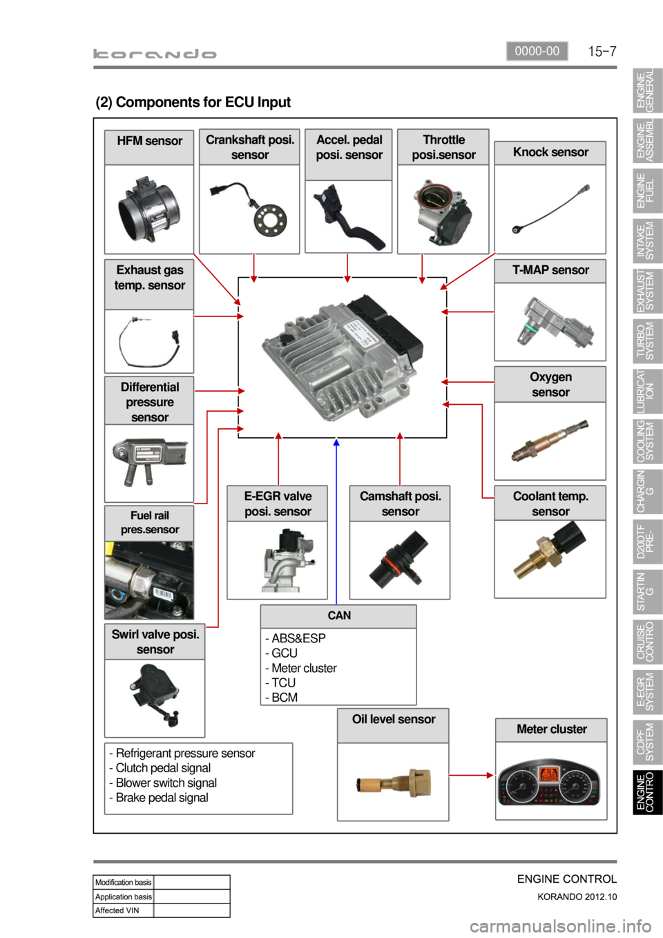
(2) Components for ECU Input
Crankshaft posi.
sensorAccel. pedal
posi. sensorThrottle
posi.sensor
Knock sensor
T-MAP sensor
Camshaft posi.
sensor
CAN
- ABS&ESP
- GCU
- Meter cluster
- TCU
- BCM
- Refrigerant pressure sensor
- Clutch pedal signal
- Blower switch signal
- Brake pedal signal
Oil level sensor
Page 285 of 1082
15-90000-00
2) ECU Control
(1) Function
a. ECU Function
ECU receives and analyzes signals from various sensors and then modifies those signals into
permissible voltage levels and analyzes to control respective actuators.
ECU microprocessor calculates injection period and injection timing proper for engine piston speed and
crankshaft angle based on input data and stored specific map to control the engine power and emission
gas.
Output signal of the ECU microprocessor drives pressure control valve to control the rail pressure and
activates injector solenoid valve to control the fuel injection period and injection timing; so controls
various actuators in response to engine changes. Auxiliary function of ECU has adopted to reduce
emission gas, improve fuel economy and enhance safety, comforts and conveniences. For example,
there are EGR, booster pressure control, autocruise (export only) and immobilizer and adopted CAN
communication to exchange data among electrical systems (automatic T/M and brake system) in the
vehicle fluently. And Scanner can be used to diagnose vehicle status and defectives.
<00760097008c00990088009b00900095008e0047009b008c00940097008c00990088009b009c0099008c0047009900880095008e008c00470096008d0047006c006a007c00470090009a0047009500960099009400880093009300a000470054005b005700
47009b009600470052005f005c00b6006a004700880095008b> protected from factors like oil,
water and electromagnetism and there should be no mechanical shocks.
To control the fuel volume precisely under repeated injections, high current should be applied instantly
so there is injector drive circuit in the ECU to generate necessary current during injector drive stages.
Current control circuit divides current applying time (injection time) into full-in-current-phase and hold-
current-phase and then the injectors should work very correctly under every working condition.
b. Control Function
Controls by operating stages
To make optimum combustion under every operating stage, ECU should calculate proper injection
volume in each stage by considering various factors.
Starting injection volume control
During initial starting, injecting fuel volume will be calculated by function of temperature and engine
cranking speed. Starting injection continues from when the ignition switch is turned to ignition
position to till the engine reaches to allowable minimum speed.
Driving mode control
If the vehicle runs normally, fuel injection volume will be calculated by accelerator pedal travel and
engine rpm and the drive map will be used to match the drivers inputs with optimum engine power. -
-
-
Page 286 of 1082
15-10
(2) Fuel Control
a. Fuel Pressure Control Elements
Pressure control consists of 2 principles.
Determines rail pressure according to engine operating conditions.
Controls IMV to make the rail pressure to reach to the required value. -
-
Pressure in the fuel rail is determined according to engine speed and load on the engine.
When engine speed and load are high
The degree of turbulence is very great and the fuel can be injected at very high pressure in order to
optimize combustion.
When engine speed and load are low
The degree of turbulence is low. If injection pressure is too high, the nozzle's penetration will be
excessive and part of the fuel will be sprayed directly onto the sides of the cylinder, causing
incomplete combustion. So there occurs smoke and damages engine durability. -
-
Fuel pressure is corrected according to air temperature, coolant temperature and atmospheric pressure
and to take account of the added ignition time caused by cold running or by high altitude driving. A
special pressure demand is necessary in order to obtain the additional flow required during starts. This
demand is determined according to injected fuel and coolant temperature.
b. Fuel Pressure Control
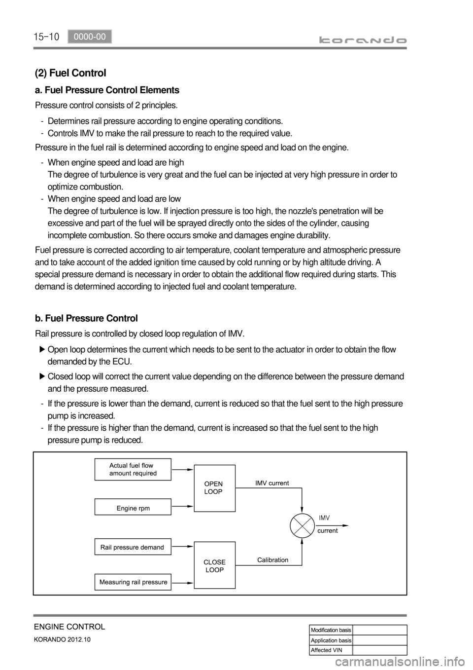
Open loop determines the current which needs to be sent to the actuator in order to obtain the flow
demanded by the ECU. ▶
Closed loop will correct the current value depending on the difference between the pressure demand
and the pressure measured. ▶
If the pressure is lower than the demand, current is reduced so that the fuel sent to the high pressure
pump is increased.
If the pressure is higher than the demand, current is increased so that the fuel sent to the high
pressure pump is reduced. -
-
Rail pressure is controlled by closed loop regulation of IMV.
Page 287 of 1082
15-110000-00
c. Fuel Injection Control
Injection control is used in order to determine the characteristics of the pulse which is sent to the
injectors.
Injection control consists as below.
Injection timing
Injection volume
Translating fuel injection timing and injection volume into values which can be interpreted by the
injector driver. -
-
-
Main injection timing control ▶
The pulse necessary for the main injection is determined as a function of the engine speed and of the
injected flow.
The elements are:
A first correction is made according to the air and coolant temperatures.
This correction makes it possible to adapt the timing to the operating temperature of the engine.
When the engine is warm, the timing can be retarded to reduce the combustion temperature and
polluting emissions (NOx). When the engine is cold, the timing advance must be sufficient to allow
the combustion to begin correctly.
A second correction is made according to the atmospheric pressure.
This correction is used to adapt the timing advance as a function of the atmospheric pressure and
therefore the altitude.
A third correction is made according to the coolant temperature and the time which has passed since
starting.
This correction allows the injection timing advance to be increased while the engine is warming up
(initial 30 seconds). The purpose of this correction is to reduce the misfiring and instabilities which are
liable to occur after a cold start.
A fourth correction is made according to the pressure error.
This correction is used to reduce the injection timing advance when the pressure in the rail is higher
than the pressure demand.
A fifth correction is made according to the rate of EGR.
This correction is used to correct the injection timing advance as a function of the rate of exhaust gas
recirculation.
When the EGR rate increases, the injection timing advance must in fact be increased in order to
compensate for the fall in termperature in the cylinder. -
-
-
-
-
During starting, the injection timing must be retarded in order to position the start of combustion close to
the TDC. To do this, special mapping is used to determine the injection timing advance as a function of
the engine speed and of the water temperature.