gas type SSANGYONG KORANDO 2012 Service Manual
[x] Cancel search | Manufacturer: SSANGYONG, Model Year: 2012, Model line: KORANDO, Model: SSANGYONG KORANDO 2012Pages: 1082, PDF Size: 96.1 MB
Page 103 of 1082
01-70000-00
3) General Instructions
Before lifting up the vehicle with a lift, correctly support the lifting points.
When using a jack, park the vehicle on a level ground and place the wheel chocks under the tires.
Position the jack under the frame and lift up the vehicle and then support with chassis stand before
service work.
Make sure to disconnect the negative (-) cable from the battery to prevent any damage to electric
systems.
If you have to work on vehicle, cover the seats and floor with protection covers to avoid any
damage and contamination.
Brake fluid and anti-freeze can damage the painted surface of body. So carefully handle them
during service work.
To improve the efficiency of service work, use only recommended and specified tools.
Use only Ssangyong genuine spare parts.
Never reuse the cotter pin, gasket, O-ring, oil seal, lock washer and self-locking nut. Replace them
with new ones. If reused, normal functions cannot be maintained.
Store the disassembled parts as a set based on disassembly order and unit.
Pay particular attention not to miss or mix the fasteners.
If necessary, especially for inspection, clean the removed parts completely.
Apply the oil or grease on the running and sliding surfeces before installation. Use the specified
sealant and gasket to prevent leakage if necessary.
Tighten the fasteners with the specified tightening torque.
As a final stage of service work, check if the serviced system is working properly and the problem
has been eliminated clearly. (1)
(2)
(3)
(4)
(5)
(6)
(7)
(8)
(9)
(10)
(11)
(12)
(13)
(14)
(15) Remove the engine and transaxle as a set.
Korando is FF (Front Engine Front Drive) type vehicle, and engine and powertrain system are
integrated into a module. Therefore, 2-post lift and general equipment are necessary when working
on the engine and transmission.
Major equipment: Engine and transmission jack, Engine stand, Engine crane, Transmission jack,
Engine hanger -
-
Page 118 of 1082
02-110000-00
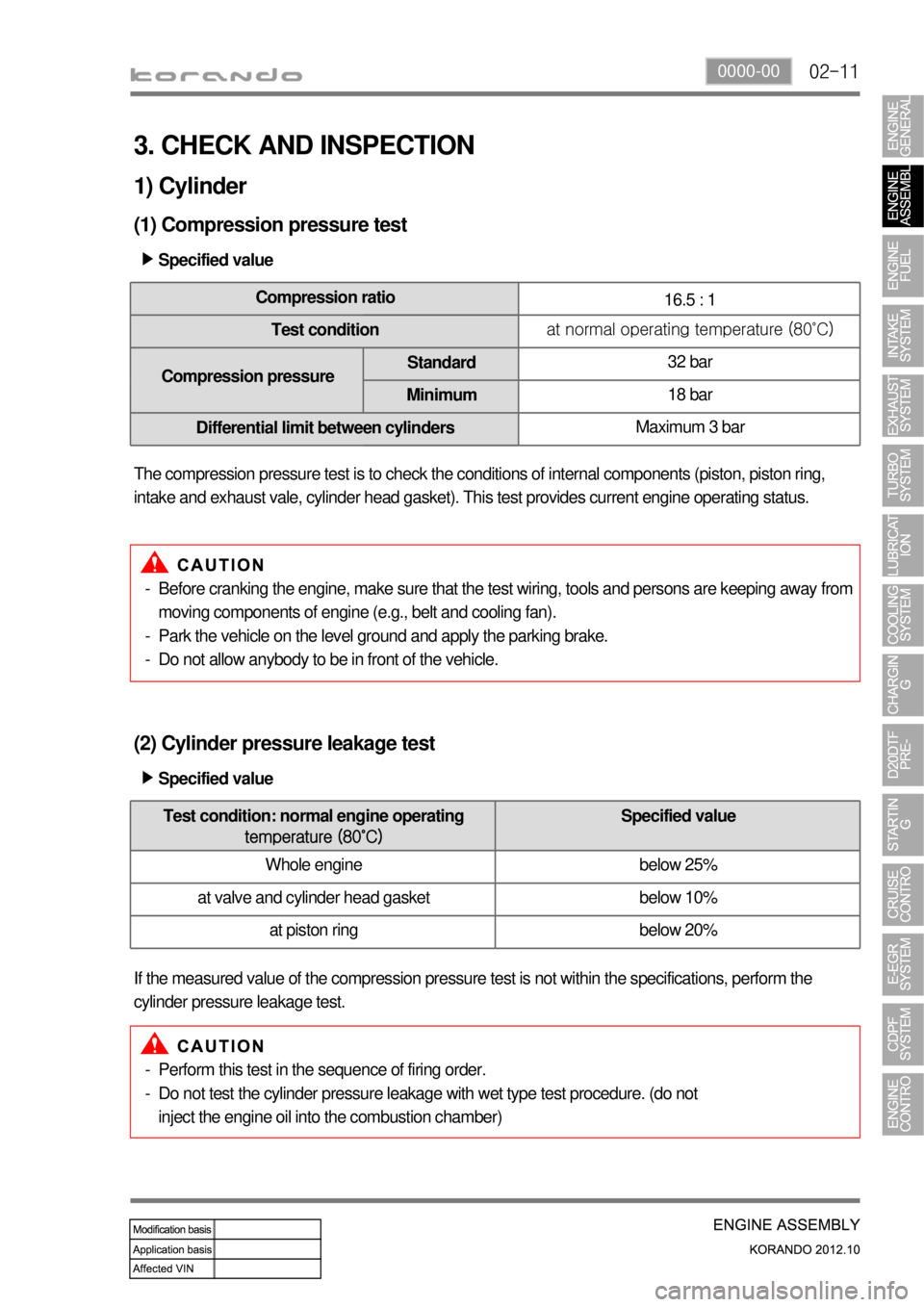
3. CHECK AND INSPECTION
1) Cylinder
(1) Compression pressure test
Specified value ▶
Compression ratio
16.5 : 1
Test conditionat normal operating temperature (80˚C)
Compression pressureStandard32 bar
Minimum18 bar
Differential limit between cylindersMaximum 3 bar
The compression pressure test is to check the conditions of internal components (piston, piston ring,
intake and exhaust vale, cylinder head gasket). This test provides current engine operating status.
Before cranking the engine, make sure that the test wiring, tools and persons are keeping away from
moving components of engine (e.g., belt and cooling fan).
Park the vehicle on the level ground and apply the parking brake.
Do not allow anybody to be in front of the vehicle. -
-
-
(2) Cylinder pressure leakage test
If the measured value of the compression pressure test is not within the specifications, perform the
cylinder pressure leakage test.Specified value ▶
Perform this test in the sequence of firing order.
Do not test the cylinder pressure leakage with wet type test procedure. (do not
inject the engine oil into the combustion chamber) -
-
Test condition: normal engine operating
temperature (80˚C)Specified value
Whole engine below 25%
at valve and cylinder head gasket below 10%
at piston ring below 20%
Page 124 of 1082
02-170000-00
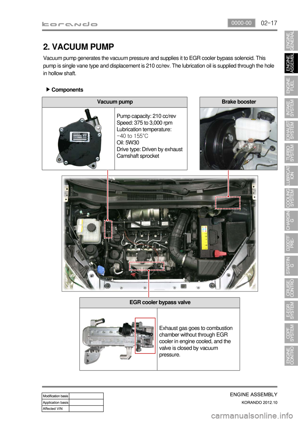
EGR cooler bypass valve
Exhaust gas goes to combustion
chamber without through EGR
cooler in engine cooled, and the
valve is closed by vacuum
pressure.
2. VACUUM PUMP
Vacuum pump generates the vacuum pressure and supplies it to EGR cooler bypass solenoid. This
pump is single vane type and displacement is 210 cc/rev. The lubrication oil is supplied through the hole
in hollow shaft.
Components ▶
Vacuum pump
Pump capacity: 210 cc/rev
Speed: 375 to 3,000 rpm
Lubrication temperature:
-40 to 155°C
Oil: 5W30
Drive type: Driven by exhaust
Camshaft sprocketBrake booster
Page 194 of 1082

06-170000-00
1. SYSTEM DESCRIPTION OF E-VGT
(Electric-Variable Geometry Turbine)
A turbocharger is a centrifugal compressor powered by a high speed turbine that is driven by an engine's
exhaust gases. Its benefit lies with the compressor increasing the mass of air entering the engine (forced
induction), thereby resulting in greater performance (for either, or both, power and efficiency). As the
turbine, at exhaust end, is rotated by exhaust gas pressure the impeller, at intake end, gets rotated to
send air around center of the impeller, being circumferentially accelerated by the centrifugal force, into
the diffuser. The air, which has been introduced to the diffuser having a passage with big surface,
transforms its speed energy into the pressure energy while being supplied to the cylinder improving the
volume efficiency. Also, the exhaust efficiency improves as the exhaust turbine rotates. The
turbocharger is often referred to as the exhaust turbine turbocharger.
The E-VGT system installed to the D20DTF engine variably controls the passages of the turbine
housing to regulate the flow rate of the exhaust gas. The actuator of E-VGT is a DC motor actuator (E-
Actuator) which controls more quickly and precisely than the previous vacuum type actuator.
The engine ECU controls the E-Actuator electronically as follows:
Diffuser: With the meaning of spreading out it is a device that transforms fluid's speed energy into the
pressure energy by enlarging the fluid's passage to slow down the flow.
At low speed: Narrows the flow passage for the exhaust gas, resulting in increasing the flow speed
of the exhaust gas and running the turbine quickly and powerfully.
At high speed: Expands the flow passage for the exhaust gas, resulting in increasing the mass flow
of the exhaust gas and running the turbine more powerfully. -
-
Page 195 of 1082
06-18
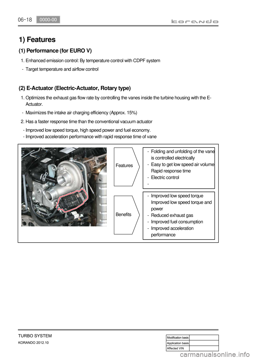
Maximizes the intake air charging efficiency (Approx. 15%) -Optimizes the exhaust gas flow rate by controlling the vanes inside the turbine housing with the E-
Actuator. 1.
(2) E-Actuator (Electric-Actuator, Rotary type)
Target temperature and airflow control -Enhanced emission control: By temperature control with CDPF system 1.
(1) Performance (for EURO V)
Has a faster response time than the conventional vacuum actuator 2.
Improved low speed torque, high speed power and fuel economy.
Improved acceleration performance with rapid response time of vane -
-
1) Features
Features
BenefitsFolding and unfolding of the vane
is controlled electrically
Easy to get low speed air volume
Rapid response time
Electric control -
-
-
-
Improved low speed torque
Improved low speed torque and
power
Reduced exhaust gas
Improved fuel consumption
Improved acceleration
performance -
-
-
-
Page 261 of 1082

13-31793-01
E-EGR bypass valve Solenoid valve Drivien byVacuum
(Solenoid valve)
1. SPECIFICATION
Item
E-EGR valve Motor EGR response time 50 mS
Driven by DC motor
Valve EGR gas flow rate 120 Kg/h
Position sensor Sensing type Hall sensor
Supply voltage 5V ± 10%
Signal range 5% ~ 95%
Max. current consumption<15mA
E-EGR cooler Cooling capacity 8.3 kW or more
Coolin fin type Wavy fin
Coller type U-shaped
Page 300 of 1082

15-24
HFM sensor
(intake air temp.)
Oxygen sensorD20DTF ECU
T-MAP sensor
(5) EGR control
a. Overview
The EGR (Electric-Exhaust Gas Recirculation) valve reduces the NOx emission level by recirculating
some of the exhaust gas to the intake system.
The major difference with the previous EURO 4 type, is that the DC motor with improved response rate
according to the EURO 5 regulation. The solenoid type actuator is used in the conventional model, but in
this new model, the DC motor type actuator with improved response rate is adopted. Also the hall senso
r
which provides a more stabilized signal than the potentiometer, and the EGR bypass flap which
improves engine warming up efficiency are also used. The HFM sensor and the position sensor are
used to feedback the amount of EGR for both EURO 4 and EURO 5.
b. Components
Electronic
throttle body
Coolant
temp.sensor
E-EGR valveCrankshaft posi.
sensor
Accelerator
pedalE-EGR cooler
Page 331 of 1082
01-70000-00
3) General Instructions
Before lifting up the vehicle with a lift, correctly support the lifting points.
When using a jack, park the vehicle on a level ground and place the wheel chocks under the tires.
Position the jack under the frame and lift up the vehicle and then support with chassis stand before
service work.
Make sure to disconnect the negative (-) cable from the battery to prevent any damage to electric
systems.
If you have to work on vehicle, cover the seats and floor with protection covers to avoid any
damage and contamination.
Brake fluid and anti-freeze can damage the painted surface of body. So carefully handle them
during service work.
To improve the efficiency of service work, use only recommended and specified tools.
Use only Ssangyong genuine spare parts.
Never reuse the cotter pin, gasket, O-ring, oil seal, lock washer and self-locking nut. Replace them
with new ones. If reused, normal functions cannot be maintained.
Store the disassembled parts as a set based on disassembly order and unit.
Pay particular attention not to miss or mix the fasteners.
If necessary, especially for inspection, clean the removed parts completely.
Apply the oil or grease on the running and sliding surfeces before installation. Use the specified
sealant and gasket to prevent leakage if necessary.
Tighten the fasteners to the specified tightening torque.
As a final stage of service work, check if the serviced system is working properly and the problem
has been eliminated clearly. (1)
(2)
(3)
(4)
(5)
(6)
(7)
(8)
(9)
(10)
(11)
(12)
(13)
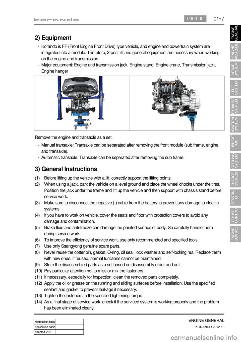
(14) Remove the engine and transaxle as a set.
Manual transaxle: Transaxle can be separated after removing the front module (sub frame, engine
and transaxle).
Automatic transaxle: Transaxle can be separated after removing the sub frame. -
-
2) Equipment
Korando is FF (Front Engine Front Drive) type vehicle, and engine and powertrain system are
integrated into a module. Therefore, 2-post lift and general equipment are necessary when working
on the engine and transmission.
Major equipment: Engine and transmission jack, Engine stand, Engine crane, Transmission jack,
Engine hanger -
-
Page 393 of 1082

03-32221-01
1. SPECIFICATION
Unit Specification
Fuel systemFuel Unleaded gasoline
Fuel injection MPI (Muilt Point Injecter) type
Fuel supply Returnless Fuel System
Fuel tankCapacity 57 L
Material Plastic
Fuel sender Dual sender type
Fuel filter Service interval Change every 100,000 km
Fuel pump Pressure 3.8 bar
InjectorColor Black
Capacity 187.2 g/min
Page 396 of 1082

03-6
Returnless Type
1. OVERVIEW
The fuel system is a returnless type that the fuel pressure regulator is mounted inside the fuel tank.
The engine ECU controls the fuel injection in each injector electronically.
According to the engine loads, the engine ECU draws or cuts off the evaporated gas in canister into the
combustion chamber. The fuel system consists of fuel tank, fuel lines, fuel pump and fuel pressure
regulator.
Fuel supply line to
sub tank
Fuel return lineFuel supply line
Maintain 3.8 bar