tire type SSANGYONG KORANDO 2012 Service Manual
[x] Cancel search | Manufacturer: SSANGYONG, Model Year: 2012, Model line: KORANDO, Model: SSANGYONG KORANDO 2012Pages: 1082, PDF Size: 96.1 MB
Page 103 of 1082
01-70000-00
3) General Instructions
Before lifting up the vehicle with a lift, correctly support the lifting points.
When using a jack, park the vehicle on a level ground and place the wheel chocks under the tires.
Position the jack under the frame and lift up the vehicle and then support with chassis stand before
service work.
Make sure to disconnect the negative (-) cable from the battery to prevent any damage to electric
systems.
If you have to work on vehicle, cover the seats and floor with protection covers to avoid any
damage and contamination.
Brake fluid and anti-freeze can damage the painted surface of body. So carefully handle them
during service work.
To improve the efficiency of service work, use only recommended and specified tools.
Use only Ssangyong genuine spare parts.
Never reuse the cotter pin, gasket, O-ring, oil seal, lock washer and self-locking nut. Replace them
with new ones. If reused, normal functions cannot be maintained.
Store the disassembled parts as a set based on disassembly order and unit.
Pay particular attention not to miss or mix the fasteners.
If necessary, especially for inspection, clean the removed parts completely.
Apply the oil or grease on the running and sliding surfeces before installation. Use the specified
sealant and gasket to prevent leakage if necessary.
Tighten the fasteners with the specified tightening torque.
As a final stage of service work, check if the serviced system is working properly and the problem
has been eliminated clearly. (1)
(2)
(3)
(4)
(5)
(6)
(7)
(8)
(9)
(10)
(11)
(12)
(13)
(14)
(15) Remove the engine and transaxle as a set.
Korando is FF (Front Engine Front Drive) type vehicle, and engine and powertrain system are
integrated into a module. Therefore, 2-post lift and general equipment are necessary when working
on the engine and transmission.
Major equipment: Engine and transmission jack, Engine stand, Engine crane, Transmission jack,
Engine hanger -
-
Page 331 of 1082
01-70000-00
3) General Instructions
Before lifting up the vehicle with a lift, correctly support the lifting points.
When using a jack, park the vehicle on a level ground and place the wheel chocks under the tires.
Position the jack under the frame and lift up the vehicle and then support with chassis stand before
service work.
Make sure to disconnect the negative (-) cable from the battery to prevent any damage to electric
systems.
If you have to work on vehicle, cover the seats and floor with protection covers to avoid any
damage and contamination.
Brake fluid and anti-freeze can damage the painted surface of body. So carefully handle them
during service work.
To improve the efficiency of service work, use only recommended and specified tools.
Use only Ssangyong genuine spare parts.
Never reuse the cotter pin, gasket, O-ring, oil seal, lock washer and self-locking nut. Replace them
with new ones. If reused, normal functions cannot be maintained.
Store the disassembled parts as a set based on disassembly order and unit.
Pay particular attention not to miss or mix the fasteners.
If necessary, especially for inspection, clean the removed parts completely.
Apply the oil or grease on the running and sliding surfeces before installation. Use the specified
sealant and gasket to prevent leakage if necessary.
Tighten the fasteners to the specified tightening torque.
As a final stage of service work, check if the serviced system is working properly and the problem
has been eliminated clearly. (1)
(2)
(3)
(4)
(5)
(6)
(7)
(8)
(9)
(10)
(11)
(12)
(13)
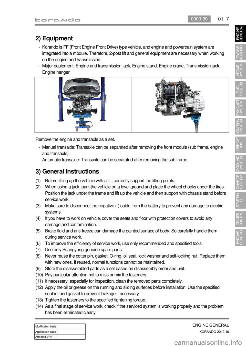
(14) Remove the engine and transaxle as a set.
Manual transaxle: Transaxle can be separated after removing the front module (sub frame, engine
and transaxle).
Automatic transaxle: Transaxle can be separated after removing the sub frame. -
-
2) Equipment
Korando is FF (Front Engine Front Drive) type vehicle, and engine and powertrain system are
integrated into a module. Therefore, 2-post lift and general equipment are necessary when working
on the engine and transmission.
Major equipment: Engine and transmission jack, Engine stand, Engine crane, Transmission jack,
Engine hanger -
-
Page 352 of 1082
02-6
3. GUIDELINES ON ENGINE SERVICE
G20DF engine is for FF (Front Engine Front Drive) type vehicle. Therefore, there are some deferent
maintenance and repair works compared to the engine for FR (Front Engine Rear Drive) type vehicle.
For safe and correct works, you must observe the working procedures and instructions in this manual.
And, use the designated tools as follow:
: Power train mounting stand / Engine hanger / Engine stand / Heavy duty engine jack.
Cautions before service works ▶
G20DF engine is FF (Front Engine Front Drive) type engine, and the engine and transmission are
integrated in a same module. Remember that there are many differences compared to
conventional engine in FR (Front Engine Rear Drive) type SUV vehicle.
To remove the engine, use the dedicated equipments such as engine jack, transmission jack,
engine stand and engine crane (1 ton).
To prevent the engine from abruptly starting during service in engine compartment, never allow
anybody to stay in the vehicle.
Make sure to disconnect the negative (-) cable from the battery to prevent any damage to electric
systems.
Make sure to clean the working area and to prepare the necessary tools before service works.
Always place the ignition switch to OFF position if not required. Otherwise, there could be
unexpected damage to electric devices or personal injuries due to short-circuit..
To prevent the foreign material from entering into the fuel injection system, completely seal the
inlets of HP pump, fuel hoses and high pressure pipes.
Do not remove the engine while supporting the oil pan with a jack. -
-
-
-
-
-
-
Lifting up the vehicle ▶
Before lifting up the vehicle with a lift, correctly support the lifting points.
To prevent the vehicle from rolling down, put the chocks under the tires (when using a 4-post lift).
Make sure to support the correct lifting points (when using a 2-post lift). -
-
-
Page 824 of 1082

01-14
Stabilizer bar assembly
The stabilizer bar assembly is not activated if the left/right
wheels move up/down simultaneously, but if both wheels
move up/down differently it is activated with frame to
minimize the tilting of the body.
5. FRONT SUSPENSION COMPONENT LAYOUT
Front suspension supports the vehicle weight and absorber the vibration from tires. And, in this type of
suspension, the steering linkage tie rod is mounted on the knuckle. The Macpherson Strut suspension
is an independent suspension which has a spring on the strut with a built-in shock absorber. The lower
arm is installed on sub frame and large strut damper is installed on the knuckle to support the tire.
Lower arm assembly
The lower arm assembly connects the frame and
knuckle. It supports the load transferred to the tire
knuckle, relieves the impact from the vehicle and ground
conditions, and ensures driving stability.
Stabilizer bar
Bushing
Clamp
Link
Page 833 of 1082
01-230000-00
3) General Instructions
Before lifting up the vehicle with a lift, correctly support the lifting points.
When using a jack, park the vehicle on a level ground and place the wheel chocks under the tires.
Position the jack under the frame and lift up the vehicle and then support with chassis stand before
service work.
Make sure to disconnect the negative (-) cable from the battery to prevent any damage to electric
systems.
If you have to work on vehicle, cover the seats and floor with protection covers to avoid any
damage and contamination.
Brake fluid and anti-freeze can damage the painted surface of body. So carefully handle them
during service work.
To improve the efficiency of service work, use only recommended and specified tools.
Use only Ssangyong genuine spare parts.
Never reuse the cotter pin, gasket, O-ring, oil seal, lock washer and self-locking nut. Replace them
with new ones. If reused, normal functions cannot be maintained.
Store the disassembled parts as a set based on disassembly order and unit.
Pay particular attention not to miss or mix the fasteners.
If necessary, especially for inspection, clean the removed parts completely.
Apply the oil or grease on the running and sliding surfeces before installation. Use the specified
sealant and gasket to prevent leakage if necessary.
Tighten the fasteners to the specified tightening torque.
As a final stage of service work, check if the serviced system is working properly and the problem
has been eliminated clearly. (1)
(2)
(3)
(4)
(5)
(6)
(7)
(8)
(9)
(10)
(11)
(12)
(13)
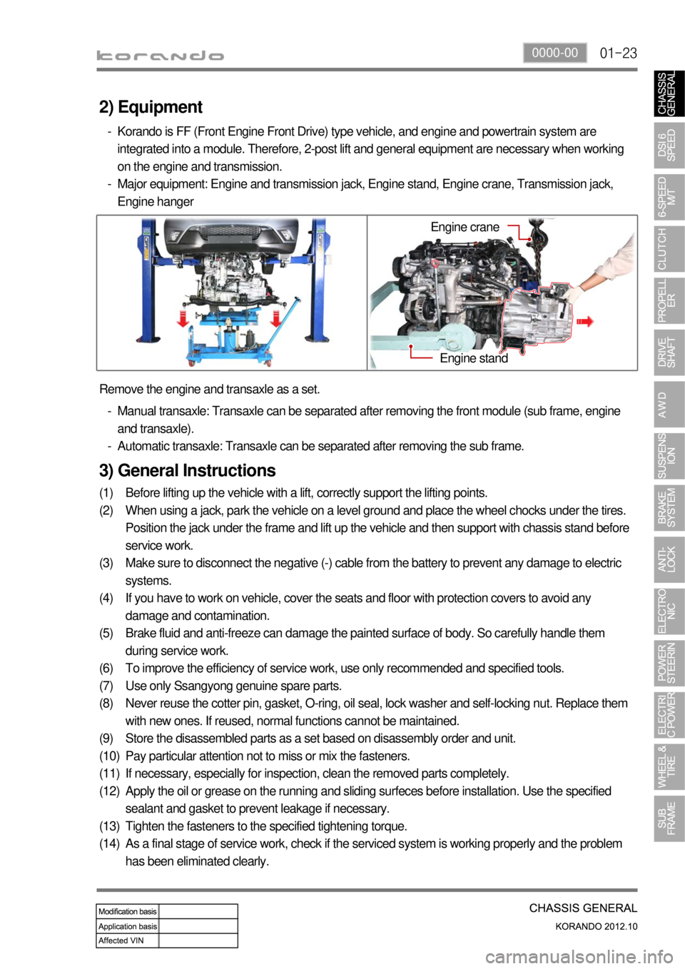
(14) Remove the engine and transaxle as a set.
Manual transaxle: Transaxle can be separated after removing the front module (sub frame, engine
and transaxle).
Automatic transaxle: Transaxle can be separated after removing the sub frame. -
-
2) Equipment
Korando is FF (Front Engine Front Drive) type vehicle, and engine and powertrain system are
integrated into a module. Therefore, 2-post lift and general equipment are necessary when working
on the engine and transmission.
Major equipment: Engine and transmission jack, Engine stand, Engine crane, Transmission jack,
Engine hanger -
-
Engine stand
Engine crane
Page 921 of 1082
08-8
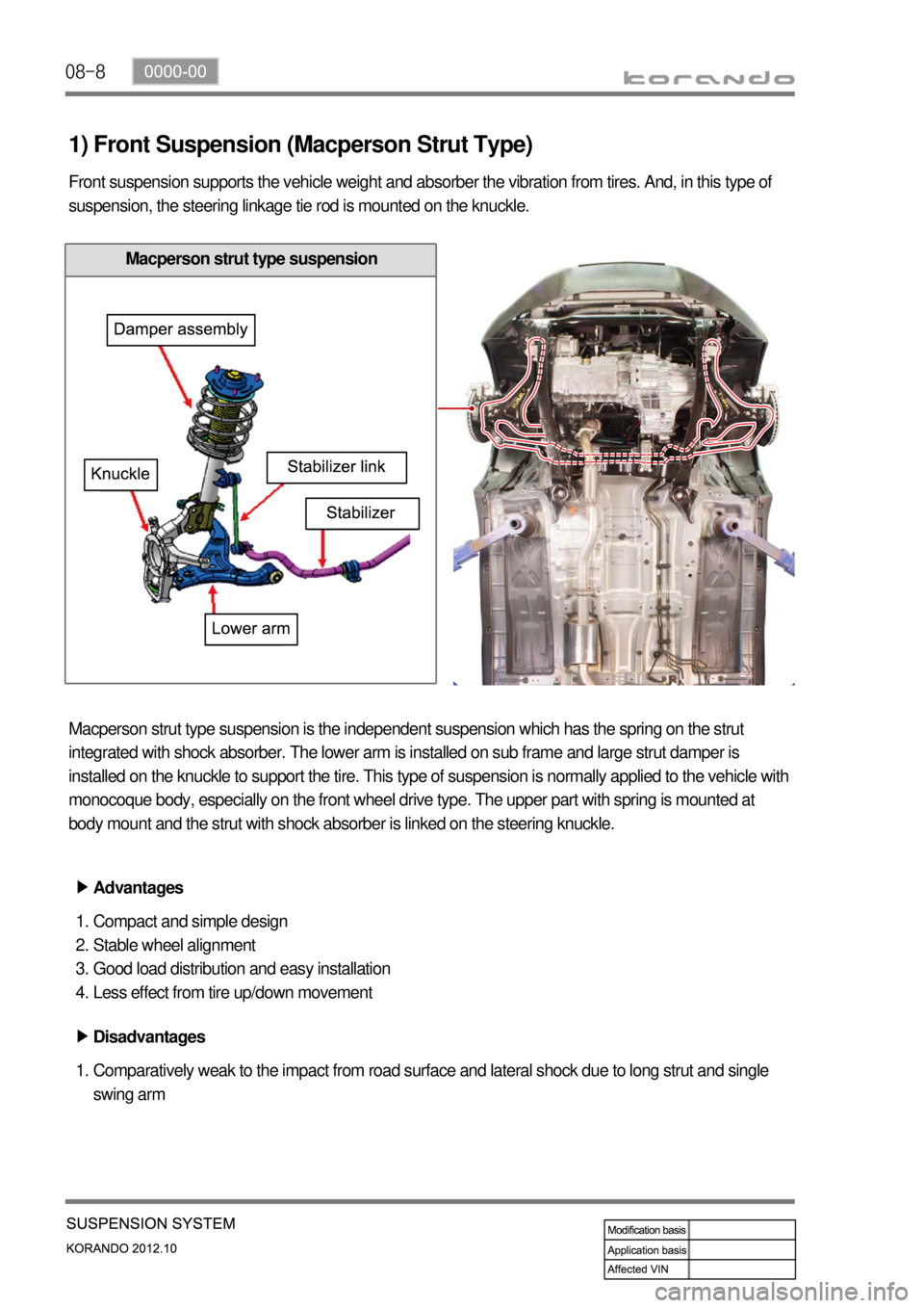
1) Front Suspension (Macperson Strut Type)
Front suspension supports the vehicle weight and absorber the vibration from tires. And, in this type of
suspension, the steering linkage tie rod is mounted on the knuckle.
Macperson strut type suspension is the independent suspension which has the spring on the strut
integrated with shock absorber. The lower arm is installed on sub frame and large strut damper is
installed on the knuckle to support the tire. This type of suspension is normally applied to the vehicle with
monocoque body, especially on the front wheel drive type. The upper part with spring is mounted at
body mount and the strut with shock absorber is linked on the steering knuckle.
Advantages ▶
Compact and simple design
Stable wheel alignment
Good load distribution and easy installation
Less effect from tire up/down movement 1.
2.
3.
4.
Disadvantages ▶
Comparatively weak to the impact from road surface and lateral shock due to long strut and single
swing arm 1.
Macperson strut type suspension
Page 991 of 1082
14-34170-00
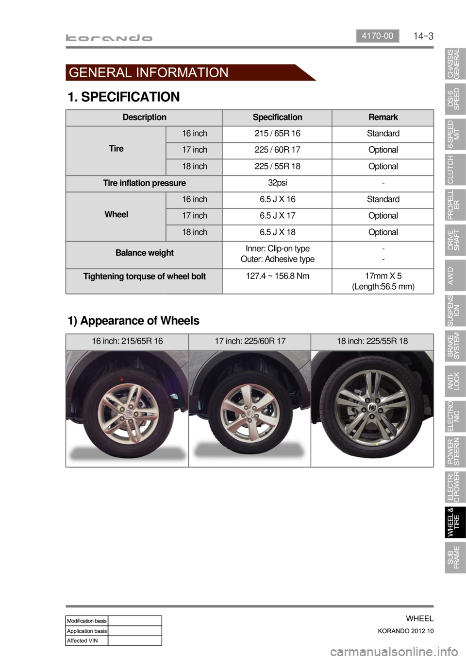
1. SPECIFICATION
1) Appearance of Wheels
16 inch: 215/65R 16 17 inch: 225/60R 17 18 inch: 225/55R 18
Description Specification Remark
Tire16 inch 215 / 65R 16 Standard
17 inch 225 / 60R 17 Optional
18 inch 225 / 55R 18 Optional
Tire inflation pressure32psi -
Wheel16 inch 6.5 J X 16 Standard
17 inch 6.5 J X 17 Optional
18 inch 6.5 J X 18 Optional
Balance weightInner: Clip-on type
Outer: Adhesive type-
-
Tightening torquse of wheel bolt127.4 ~ 156.8 Nm 17mm X 5
(Length:56.5 mm)
Page 992 of 1082
14-4
1. OVERVIEW
A radial tire uses a cord angle of 90 degrees. That is, the cord material runs in a radial or direct line from
one bead to the other across the tread. In addition, a radial tire has a belt overwrap under the tread
surface to provide greater structural stability. The belt overwrap of a radial tire distortion while the radial
structure enables high speed driving.
Tire supports the weight of the vehicle, reduces the impact from the road and at the same time,
transmits the power to propel, brake and steer on the road. It also functions to maintain a
<009d008c008f0090008a0093008c02c5009a004700940096009d008c0094008c0095009b0055004700700095004700960099008b008c00990047009b00960047008a0096009400970093008c009b008c0047009a009c008a008f0047009b0088009a009200
9a0053004700880047009b00900099008c00470094009c009a>t be structured to be a resilient
vessel of air.
There is wear limit mark on the tire, which protrudes as a strip shape located approximately 1.6 mm from
<009b008f008c0047008e009900960096009d008c004700890096009b009b0096009400550047007b008f0090009a0047009e008c0088009900470093009000940090009b0047009400880099009200470090009a004700950096009b0047009a008c008c00
950047008d0099009600940047009b008f008c00470096009c>tside so there is additional "▲"
mark on the shoulder to let the driver find the wear mark easily. To measure the tire groove depth,
measure at any point other than the point which has a wear limit mark.
The tire is worn unevenly according to the driver's driving habit, improper servicing, low tire inflation
pressure, changed tire location, etc.
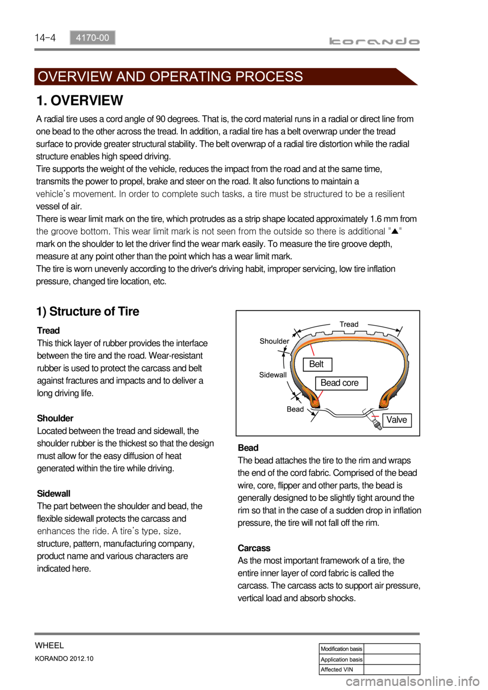
1) Structure of Tire
Tread
This thick layer of rubber provides the interface
between the tire and the road. Wear-resistant
rubber is used to protect the carcass and belt
against fractures and impacts and to deliver a
long driving life.
Shoulder
Located between the tread and sidewall, the
shoulder rubber is the thickest so that the design
must allow for the easy diffusion of heat
generated within the tire while driving.
Sidewall
The part between the shoulder and bead, the
flexible sidewall protects the carcass and
enhances the ride. A tire’s type, size,
structure, pattern, manufacturing company,
product name and various characters are
indicated here. Bead
The bead attaches the tire to the rim and wraps
the end of the cord fabric. Comprised of the bead
wire, core, flipper and other parts, the bead is
generally designed to be slightly tight around the
rim so that in the case of a sudden drop in inflation
pressure, the tire will not fall off the rim.
Carcass
As the most important framework of a tire, the
entire inner layer of cord fabric is called the
carcass. The carcass acts to support air pressure,
vertical load and absorb shocks.
Valve
Belt
Bead core
Page 996 of 1082
14-8
If weight is not equally distributed around the wheel, unbalance centrifugal force by the wheel rotation
produces vibration. As the centrifugal force is produced proportional to the square of the rotating speed,
the wheel weight should be balanced even at high speed. There are two types of the tire and wheel
balancing: static and dynamic. Abnormal vibration may also occur due to unbalanced rigidity or size of
tires.
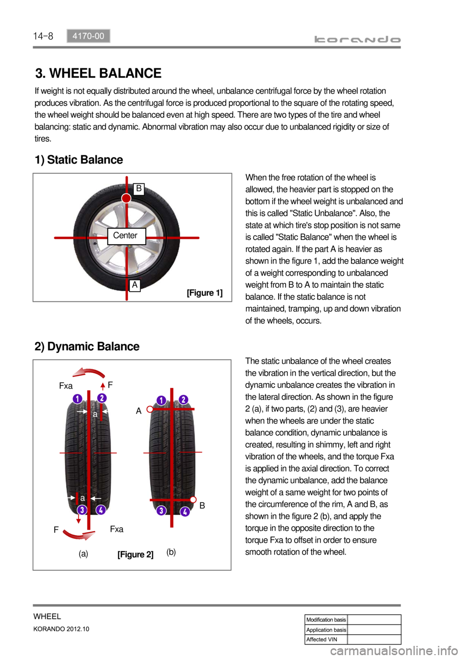
1) Static Balance
When the free rotation of the wheel is
allowed, the heavier part is stopped on the
bottom if the wheel weight is unbalanced and
this is called "Static Unbalance". Also, the
state at which tire's stop position is not same
is called "Static Balance" when the wheel is
rotated again. If the part A is heavier as
shown in the figure 1, add the balance weight
of a weight corresponding to unbalanced
weight from B to A to maintain the static
balance. If the static balance is not
maintained, tramping, up and down vibration
of the wheels, occurs.
2) Dynamic Balance
The static unbalance of the wheel creates
the vibration in the vertical direction, but the
dynamic unbalance creates the vibration in
the lateral direction. As shown in the figure
2 (a), if two parts, (2) and (3), are heavier
when the wheels are under the static
balance condition, dynamic unbalance is
created, resulting in shimmy, left and right
vibration of the wheels, and the torque Fxa
is applied in the axial direction. To correct
the dynamic unbalance, add the balance
weight of a same weight for two points of
the circumference of the rim, A and B, as
shown in the figure 2 (b), and apply the
torque in the opposite direction to the
torque Fxa to offset in order to ensure
smooth rotation of the wheel.
Center
A
B
a
a
Fxa
Fxa F
F
A
B
(a)(b)
[Figure 1]
[Figure 2]
3. WHEEL BALANCE