sensor SSANGYONG KORANDO 2013 Service Manual
[x] Cancel search | Manufacturer: SSANGYONG, Model Year: 2013, Model line: KORANDO, Model: SSANGYONG KORANDO 2013Pages: 1336, PDF Size: 92.18 MB
Page 952 of 1336

Shift lever
IP display (SVC only)
sensors in the rear bumper detect the distance to any obstacle. The PAS detects the returning signals
reflected to the obstacles at regular intervals when the vehicle is parked to indicate the display and alarm
for the distance between the obstacles by phase so as to allow the driver easy parking by securing safe
distance.
1. OVERVIEW
Buzzer for PAS
Buzzer sounds using instrument
cluster buzzer
Rearview camera
Page 953 of 1336

8790-00
PAS sensorParking aid unit
2. CONFIGURATION
Installation of PAS sensor
Page 955 of 1336

8790-00
While reversing, if obstacles are within stage 1, the warning beep sounds with long intervals. If within
stage 2, the warning beep sounds with short intervals and if within stage 3, the warning beep sounds
continuously.
Sensor detection range
Within 20 cm from the ground
(Objects may not be detected in this range.)
Buzzer interval when measuring distance
2) Rear PAS Sensor
Page 956 of 1336

Circuit diagram of ECU
Internal circuit diagram of sensors
Page 957 of 1336

8790-00
Sensor operating sequence
The ultrasonic sensors transmit ultrasonic waves
and receive the reflected waves from an obstacle
Page 958 of 1336

4. OUTPUT SPECIFICATIONS FOR SENSOR SELF-
DIAGNOSIS BUZZER SOUND
Fail condition (However, no obstacle should be within 30 cm)
1. The signal wire is open
2. The power wire (+ and -)is open -Conditions to "FAIL" in sensor diagnosis
Buzzer interval during self diagnosis
Timeout processing time for buzzer interval after measuring distance/self diagnosis: 600 ms
- If timeout is reached, the PAS returns to undetected condition.
Process while re-inputting
- After timeout, the process is performed normally if the signal required for display is received
from beginning to end. (not detectable if the signal is received in the midst of process) 1.
2.Exception/error handling
Self diagnosis is performed once when the ignition is switched on (gear shift lever in "R" position). If the
system is defective (Fail) due to open sensor or communication problem, the information for the failed
sensor is displayed as buzzer sound.
If it is normal, the warning buzzer sounds for 60 ms.
Page 984 of 1336

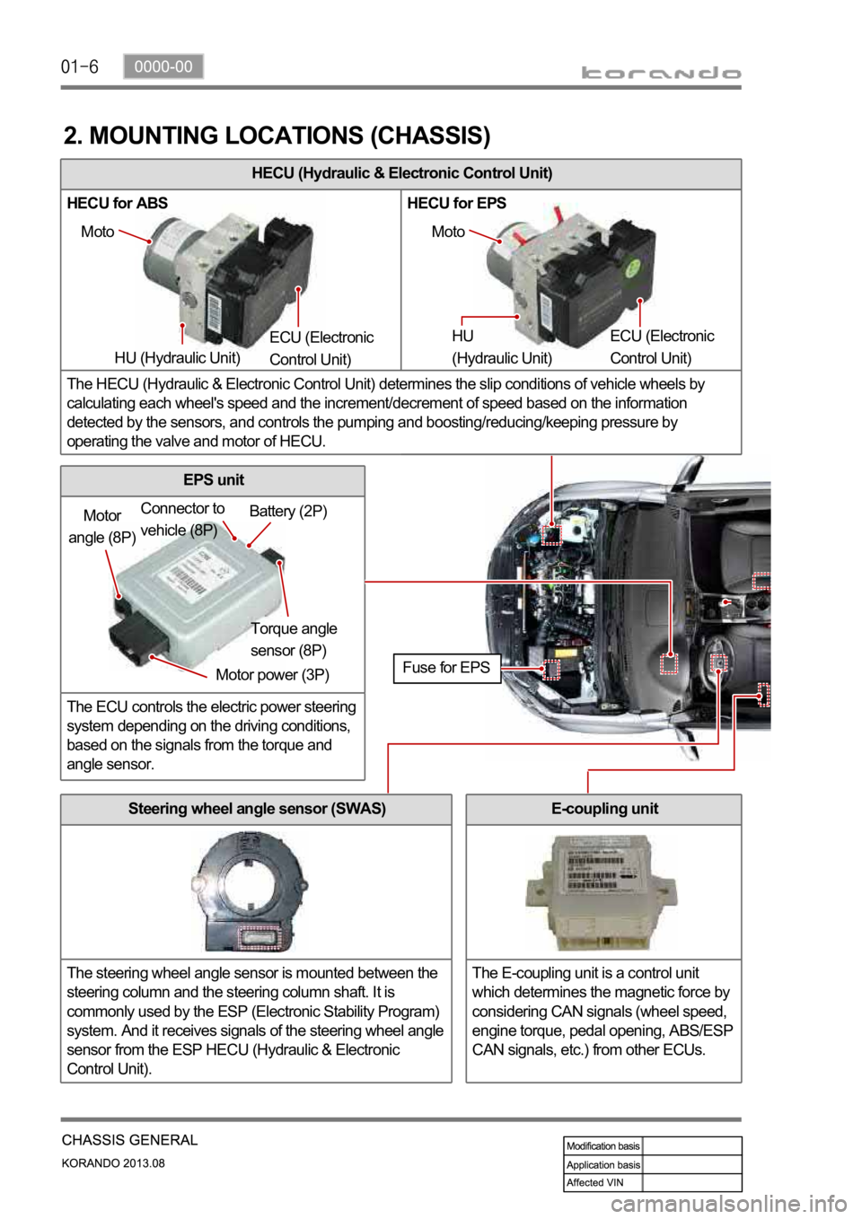
HECU (Hydraulic & Electronic Control Unit)
HECU for ABS HECU for EPS
The HECU (Hydraulic & Electronic Control Unit) determines the slip conditions of vehicle wheels by
calculating each wheel's speed and the increment/decrement of speed based on the information
detected by the sensors, and controls the pumping and boosting/reducing/keeping pressure by
operating the valve and motor of HECU.
2. MOUNTING LOCATIONS (CHASSIS)
Moto
HU (Hydraulic Unit) ECU (Electronic
Control Unit) Moto
HU
(Hydraulic Unit) ECU (Electronic
Control Unit)
Motor
angle (8P)
Motor power (3P)Torque angle
sensor (8P) Battery (2P) Connector to
vehicle (8P)
Fuse for EPS
Steering wheel angle sensor (SWAS)
The steering wheel angle sensor is mounted between the
steering column and the steering column shaft. It is
commonly used by the ESP (Electronic Stability Program)
system. And it receives signals of the steering wheel angle
sensor from the ESP HECU (Hydraulic & Electronic
Control Unit).
EPS unit
The ECU controls the electric power steering
system depending on the driving conditions,
based on the signals from the torque and
angle sensor.
E-coupling unit
The E-coupling unit is a control unit
which determines the magnetic force by
considering CAN signals (wheel speed,
engine torque, pedal opening, ABS/ESP
CAN signals, etc.) from other ECUs.
Page 985 of 1336

0000-00
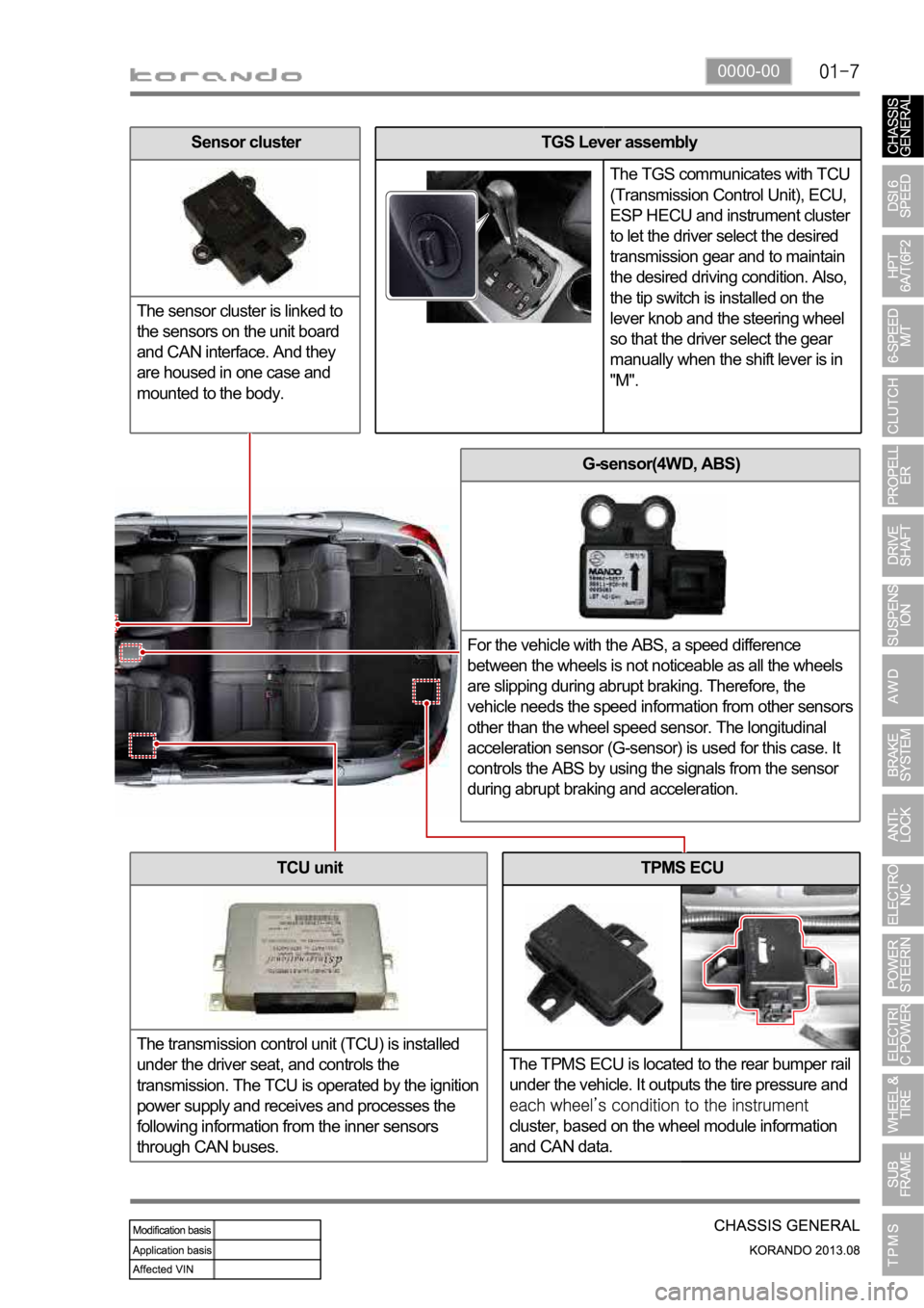
TPMS ECU
The TPMS ECU is located to the rear bumper rail
under the vehicle. It outputs the tire pressure and
cluster, based on the wheel module information
and CAN data.
G-sensor(4WD, ABS)
For the vehicle with the ABS, a speed difference
between the wheels is not noticeable as all the wheels
are slipping during abrupt braking. Therefore, the
vehicle needs the speed information from other sensors
other than the wheel speed sensor. The longitudinal
acceleration sensor (G-sensor) is used for this case. It
controls the ABS by using the signals from the sensor
during abrupt braking and acceleration.
TCU unit
The transmission control unit (TCU) is installed
under the driver seat, and controls the
transmission. The TCU is operated by the ignition
power supply and receives and processes the
following information from the inner sensors
through CAN buses.
TGS Lever assembly
The TGS communicates with TCU
(Transmission Control Unit), ECU,
ESP HECU and instrument cluster
to let the driver select the desired
transmission gear and to maintain
the desired driving condition. Also,
the tip switch is installed on the
lever knob and the steering wheel
so that the driver select the gear
manually when the shift lever is in
"M".Sensor cluster
The sensor cluster is linked to
the sensors on the unit board
and CAN interface. And they
are housed in one case and
mounted to the body.
Page 995 of 1336

0000-00
H. Parking brake
M/T A/T
The parking brake is the mechanical device to
hold the vehicle. When pulling up the lever, the
parking brake cable between the lever and the
rear drum brake trailing shoe pulls the parking
brake lining to contact to drum.
E. Rear brake assembly
The disc brake for 4WD vehicle has the same
structure with the one for 2WD vehicle, but the
appearance and knuckle shape is different from
each other.
Caliper
G. Brake pedal
Disc
F. Parking brake
4WD and 2WD
Front side2WD Rear side
The wheel speed sensor for 4WD has the same
structure and mounting location with the one for
2WD vehicle. But the rear side wheel speed
sensor for 2WD vehicle has different sensor
appearance and mounting status because the
knuckle shape is different from the 4WD vehicle.
Page 997 of 1336

0000-00
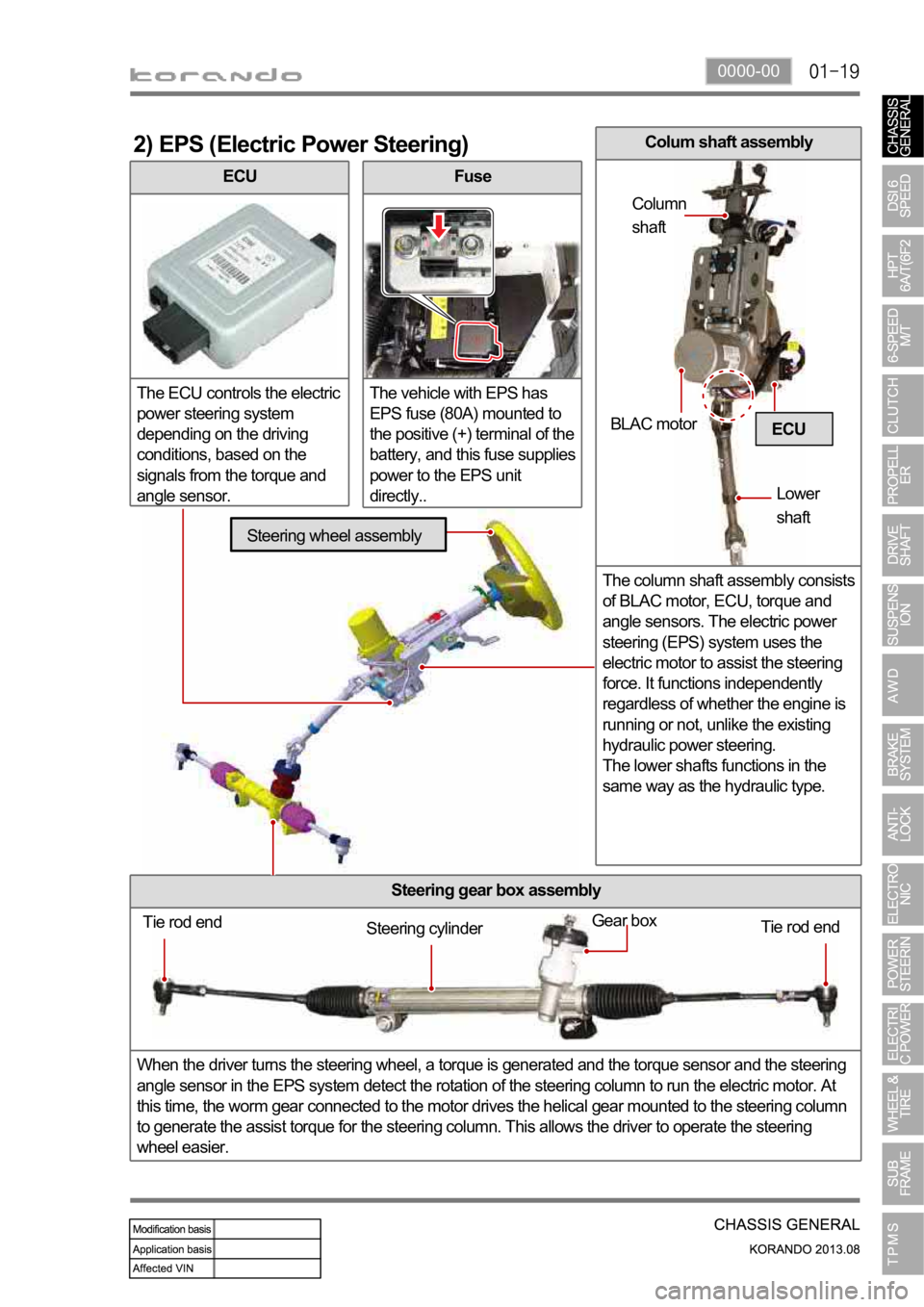
ECU
The ECU controls the electric
power steering system
depending on the driving
conditions, based on the
signals from the torque and
angle sensor.
2) EPS (Electric Power Steering)
Fuse
The vehicle with EPS has
EPS fuse (80A) mounted to
the positive (+) terminal of the
battery, and this fuse supplies
power to the EPS unit
directly..
Steering gear box assembly
When the driver turns the steering wheel, a torque is generated and the torque sensor and the steering
angle sensor in the EPS system detect the rotation of the steering column to run the electric motor. At
this time, the worm gear connected to the motor drives the helical gear mounted to the steering column
to generate the assist torque for the steering column. This allows the driver to operate the steering
wheel easier.
ECU
Tie rod end
Tie rod end Gear boxSteering cylinder
Steering wheel assembly
BLAC motor
Lower
shaft Column
shaft
Colum shaft assembly
The column shaft assembly consists
of BLAC motor, ECU, torque and
angle sensors. The electric power
steering (EPS) system uses the
electric motor to assist the steering
force. It functions independently
regardless of whether the engine is
running or not, unlike the existing
hydraulic power steering.
The lower shafts functions in the
same way as the hydraulic type.