ignition SSANGYONG KORANDO 2013 Service Manual
[x] Cancel search | Manufacturer: SSANGYONG, Model Year: 2013, Model line: KORANDO, Model: SSANGYONG KORANDO 2013Pages: 1336, PDF Size: 92.18 MB
Page 927 of 1336
7810-00
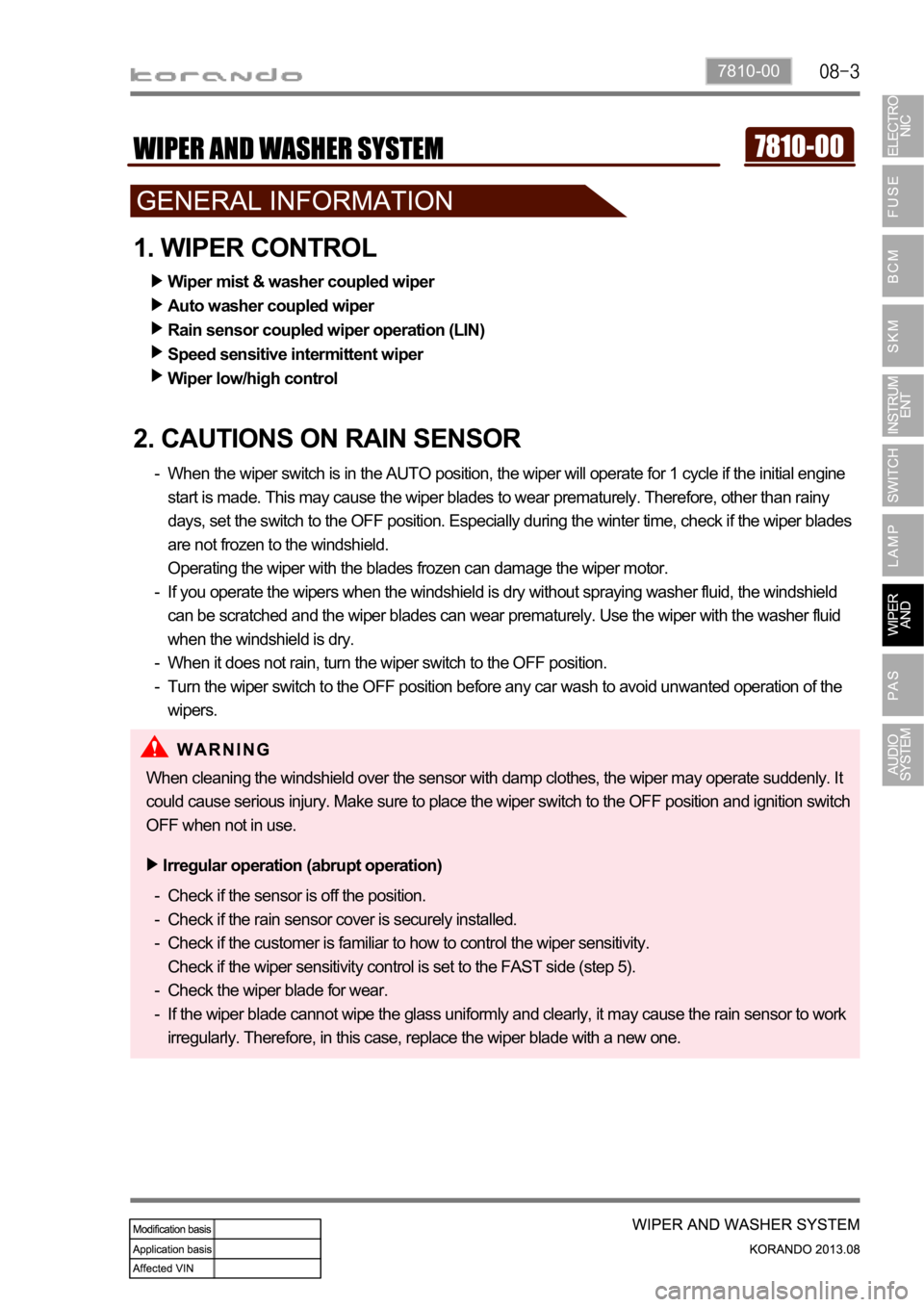
1. WIPER CONTROL
2. CAUTIONS ON RAIN SENSOR
When the wiper switch is in the AUTO position, the wiper will operate for 1 cycle if the initial engine
start is made. This may cause the wiper blades to wear prematurely. Therefore, other than rainy
days, set the switch to the OFF position. Especially during the winter time, check if the wiper blades
are not frozen to the windshield.
Operating the wiper with the blades frozen can damage the wiper motor.
If you operate the wipers when the windshield is dry without spraying washer fluid, the windshield
can be scratched and the wiper blades can wear prematurely. Use the wiper with the washer fluid
when the windshield is dry.
When it does not rain, turn the wiper switch to the OFF position.
Turn the wiper switch to the OFF position before any car wash to avoid unwanted operation of the
wipers. -
-
-
-Wiper mist & washer coupled wiper
Auto washer coupled wiper
Rain sensor coupled wiper operation (LIN)
Speed sensitive intermittent wiper
Wiper low/high control
Check if the sensor is off the position.
Check if the rain sensor cover is securely installed.
Check if the customer is familiar to how to control the wiper sensitivity.
Check if the wiper sensitivity control is set to the FAST side (step 5).
Check the wiper blade for wear.
If the wiper blade cannot wipe the glass uniformly and clearly, it may cause the rain sensor to work
irregularly. Therefore, in this case, replace the wiper blade with a new one. -
-
-
-
-Irregular operation (abrupt operation)
When cleaning the windshield over the sensor with damp clothes, the wiper may operate suddenly. It
could cause serious injury. Make sure to place the wiper switch to the OFF position and ignition switch
OFF when not in use.
Page 928 of 1336

1. WIPER AND WASHER SYSTEM
1) AUTO Washer Coupled Wiper Function
If you press the AUTO washer switch briefly with the ignition key ON and INT-AUTO switch "OFF", the
washer motor is operated for about 2 seconds to spray washer fluid once after the switch is turned ON
and the wiper relay is turned ON for 4 cycles. After that, the washer motor is operated for about 2
seconds to spray the washer fluid again and the relay is turned ON for 3 cycles and then the relay is
turned OFF.
2) Rear Washer Fluid Supply System
The front washer fluid reservoir supplies the rear washer fluid without additional washer fluid reservoir. Operating part for rear
wiper/washer
AUTO washer
switch (press)
Washer motor
Page 936 of 1336

(2) Wiper LO/HI control
The wiper LOW relay is turned on when the multifunction wiper switch is at the LO position. The wiper
HIGH relay is turned on when the wiper switch is at the HI position. When the wiper switch is at the HI
position, both the LOW relay (constant operation) and HIGH relay are operated.
The wiper motor returns to parking position and stops, even when turning off the ignition switch during
wiper operation.
The wiper relay should stay ON in low/high wiper operation mode even if the parking signal for the
wiper motor is not received. In INT/AUTO wiper operation mode, the wiper relay should be turned
OFF after 5 seconds if there is no parking signal for the wiper for 3 seconds and informs the driver of
parking position signal abnormality.
While the wiper operates at low/high speed, the front/rear washer switch can be operated but the auto
washer switch cannot.
The wiper motor returns to parking position and stops when turning off the ignition switch during wiper
operation in high mode. 1.
2.
3.
4.
5.
Page 941 of 1336
7810-00
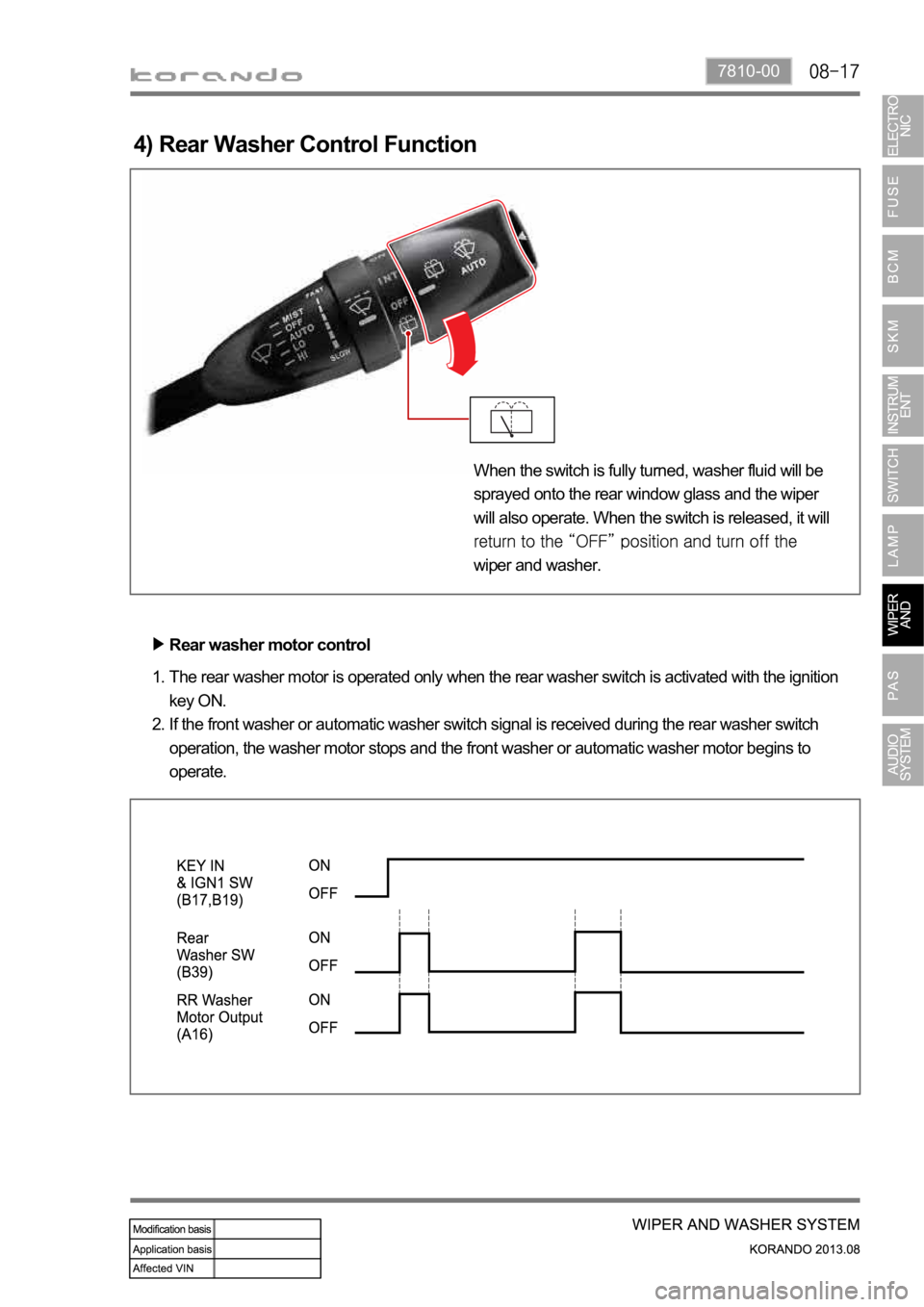
4) Rear Washer Control Function
The rear washer motor is operated only when the rear washer switch is activated with the ignition
key ON.
If the front washer or automatic washer switch signal is received during the rear washer switch
operation, the washer motor stops and the front washer or automatic washer motor begins to
operate. 1.
2.Rear washer motor control
When the switch is fully turned, washer fluid will be
sprayed onto the rear window glass and the wiper
will also operate. When the switch is released, it will
wiper and washer.
Page 944 of 1336

If the intermittent/automatic wiper switch is in "ON" position, the wiper motor does not operate even
when turning the ignition switch to ON from OFF position.
When the INT/AUTO wiper switch is turned on from off with the ignition switch ON, the wiper is
operated at low speed for the 1st cycle regardless of the rain sensor signals. After that, if the
INT/AUTO wiper switch is turned on from off, the wiper cycles one time at low speed only when the
rain sensor detects the presence of rain. 1.
2.
(2) Power-up reminder wiper
Page 949 of 1336
7810-00
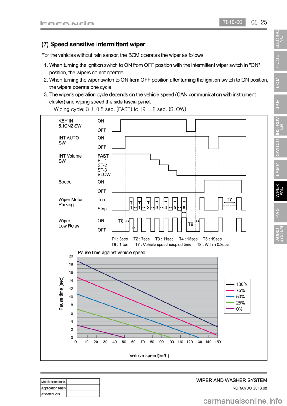
For the vehicles without rain sensor, the BCM operates the wiper as follows:
When turning the ignition switch to ON from OFF position with the intermittent wiper switch in "ON"
position, the wipers do not operate.
When turning the wiper switch to ON from OFF position after turning the ignition switch to ON position,
the wipers operate one cycle.
The wiper's operation cycle depends on the vehicle speed (CAN communication with instrument
cluster) and wiping speed the side fascia panel.
1.
2.
3.
(7) Speed sensitive intermittent wiper
Page 958 of 1336

4. OUTPUT SPECIFICATIONS FOR SENSOR SELF-
DIAGNOSIS BUZZER SOUND
Fail condition (However, no obstacle should be within 30 cm)
1. The signal wire is open
2. The power wire (+ and -)is open -Conditions to "FAIL" in sensor diagnosis
Buzzer interval during self diagnosis
Timeout processing time for buzzer interval after measuring distance/self diagnosis: 600 ms
- If timeout is reached, the PAS returns to undetected condition.
Process while re-inputting
- After timeout, the process is performed normally if the signal required for display is received
from beginning to end. (not detectable if the signal is received in the midst of process) 1.
2.Exception/error handling
Self diagnosis is performed once when the ignition is switched on (gear shift lever in "R" position). If the
system is defective (Fail) due to open sensor or communication problem, the information for the failed
sensor is displayed as buzzer sound.
If it is normal, the warning buzzer sounds for 60 ms.
Page 985 of 1336
0000-00
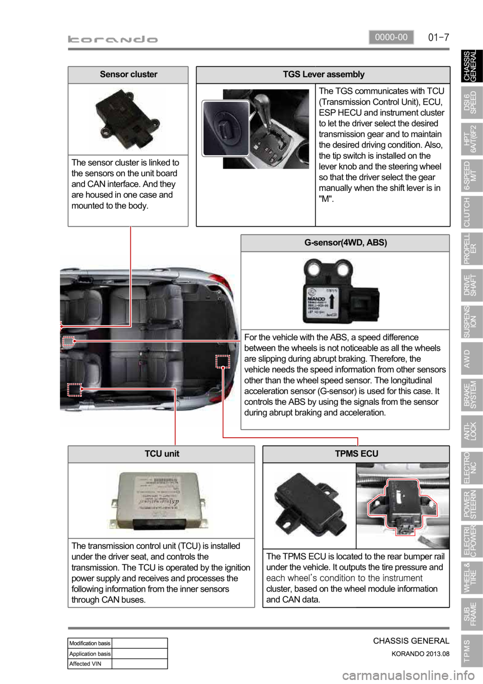
TPMS ECU
The TPMS ECU is located to the rear bumper rail
under the vehicle. It outputs the tire pressure and
cluster, based on the wheel module information
and CAN data.
G-sensor(4WD, ABS)
For the vehicle with the ABS, a speed difference
between the wheels is not noticeable as all the wheels
are slipping during abrupt braking. Therefore, the
vehicle needs the speed information from other sensors
other than the wheel speed sensor. The longitudinal
acceleration sensor (G-sensor) is used for this case. It
controls the ABS by using the signals from the sensor
during abrupt braking and acceleration.
TCU unit
The transmission control unit (TCU) is installed
under the driver seat, and controls the
transmission. The TCU is operated by the ignition
power supply and receives and processes the
following information from the inner sensors
through CAN buses.
TGS Lever assembly
The TGS communicates with TCU
(Transmission Control Unit), ECU,
ESP HECU and instrument cluster
to let the driver select the desired
transmission gear and to maintain
the desired driving condition. Also,
the tip switch is installed on the
lever knob and the steering wheel
so that the driver select the gear
manually when the shift lever is in
"M".Sensor cluster
The sensor cluster is linked to
the sensors on the unit board
and CAN interface. And they
are housed in one case and
mounted to the body.
Page 996 of 1336
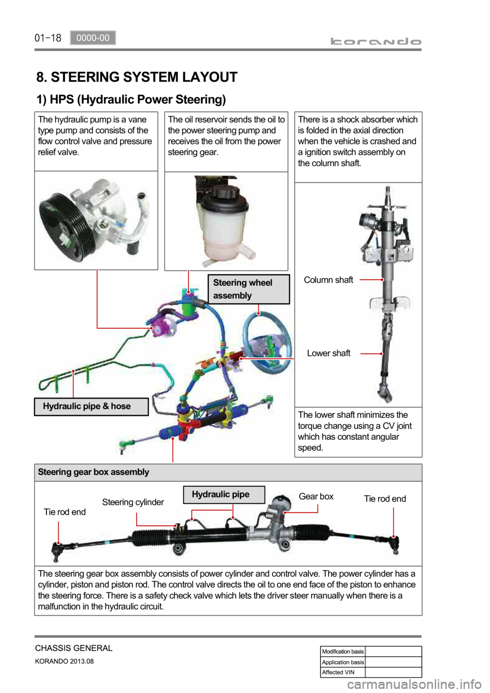
Steering gear box assembly
The steering gear box assembly consists of power cylinder and control valve. The power cylinder has a
cylinder, piston and piston rod. The control valve directs the oil to one end face of the piston to enhance
the steering force. There is a safety check valve which lets the driver steer manually when there is a
malfunction in the hydraulic circuit.
8. STEERING SYSTEM LAYOUT
1) HPS (Hydraulic Power Steering)
The hydraulic pump is a vane
type pump and consists of the
flow control valve and pressure
relief valve.The oil reservoir sends the oil to
the power steering pump and
receives the oil from the power
steering gear.There is a shock absorber which
is folded in the axial direction
when the vehicle is crashed and
a ignition switch assembly on
the column shaft.
The lower shaft minimizes the
torque change using a CV joint
which has constant angular
speed.
Tie rod endSteering cylinderGear box
Tie rod end
Hydraulic pipeColumn shaft
Lower shaft
Steering wheel
assembly
Hydraulic pipe & hose
Page 1003 of 1336
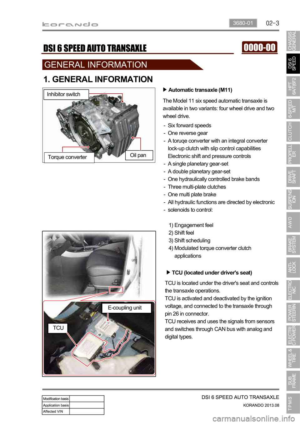
3680-01
1. GENERAL INFORMATION
Automatic transaxle (M11)
The Model 11 six speed automatic transaxle is
available in two variants: four wheel drive and two
wheel drive.
Six forward speeds
One reverse gear
A toruqe converter with an integral converter
lock-up clutch with slip control capabilities
Electronic shift and pressure controls
A single planetary gear-set
A double planetary gear-set
One hydraulically controlled brake bands
Three multi-plate clutches
One multi plate brake
All hydraulic functions are directed by electronic
solenoids to control: -
-
-
-
-
-
-
-
-
-
Engagement feel
Shift feel
Shift scheduling
Modulated torque converter clutch
applications 1)
2)
3)
4) Inhibitor switch
Oil pan
Torque converter
TCU (located under driver's seat)
TCU is located under the driver's seat and controls
the transaxle operations.
TCU is activated and deactivated by the ignition
voltage, and connected to the transaxle through
pin 26 in connector.
TCU receives and uses the signals from sensors
and switches through CAN bus with analog and
digital types.
E-coupling unit
TCU