timing SSANGYONG KORANDO 2013 User Guide
[x] Cancel search | Manufacturer: SSANGYONG, Model Year: 2013, Model line: KORANDO, Model: SSANGYONG KORANDO 2013Pages: 1336, PDF Size: 92.18 MB
Page 436 of 1336
1116-01
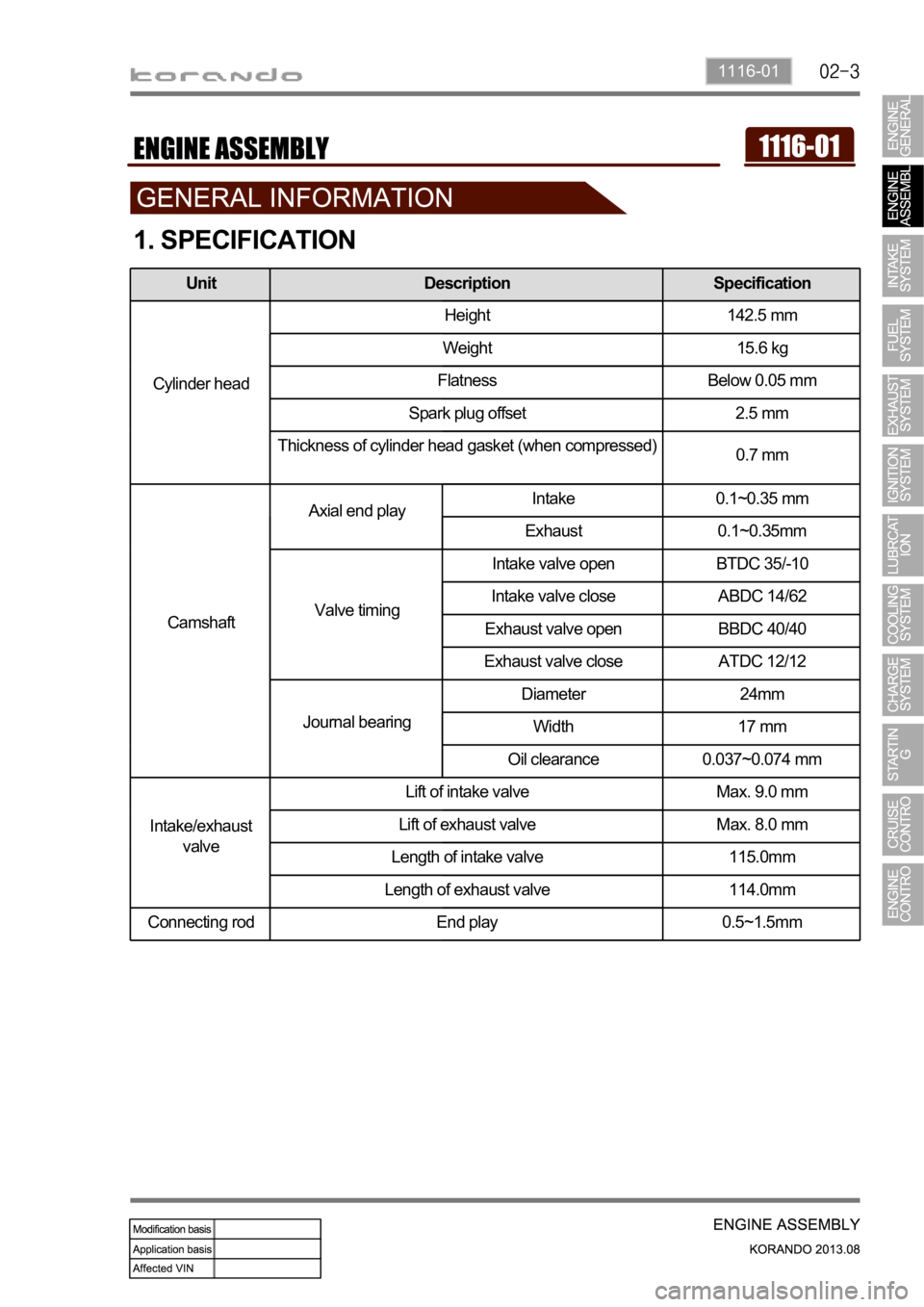
1. SPECIFICATION
Unit Description Specification
Cylinder headHeight 142.5 mm
Weight 15.6 kg
Flatness Below 0.05 mm
Spark plug offset 2.5 mm
Thickness of cylinder head gasket (when compressed)
0.7 mm
CamshaftAxial end playIntake 0.1~0.35 mm
Exhaust 0.1~0.35mm
Valve timingIntake valve open BTDC 35/-10
Intake valve close ABDC 14/62
Exhaust valve open BBDC 40/40
Exhaust valve close ATDC 12/12
Journal bearingDiameter 24mm
Width 17 mm
Oil clearance 0.037~0.074 mm
Intake/exhaust
valveLift of intake valve Max. 9.0 mm
Lift of exhaust valve Max. 8.0 mm
Length of intake valve 115.0mm
Length of exhaust valve 114.0mm
Connecting rod End play 0.5~1.5mm
Page 444 of 1336

1337-04
3) Crankshaft Pulley (CRS)
The strut type tensioner automatically adjusts the belt tension to provide the reliability and durability for
the system. And, the belt tension is decreased to minimize the friction loss and improve the belt
operating noise.Overview
Location
Crankshaft pulley (CRS)
Timing mark
Page 451 of 1336

3) Camshaft Assembly
Overview
The camshaft is hollow type, and contains the cam, octagon cam, OCV gallery, cam position rotor. The
camshaft operates the intake and exhaust valves.
Location
Exhaust camshaft
Intake camshaft
Timing marks
Align the timing marks (A) on the camshaft
flange and camshaft cap when installing the
intake/exhaust camshaft.
Page 454 of 1336

1311-01
The drive chain is single chain drive system with simple design and variable performance, and it utilizes
the hydraulic tensioner to reduce the wave impact generated by the chain. The silent chain provides the
silence during the operation. To improve NVH, the shoulder bolt has been introduced. Overview
Layout and Components
Hydraulic tensioner
Consists of tensioner housing
plug, spring, check valve, and
operated by hydraulic
pressure and spring in
tensioner
Timing chain
Chain type: Silent chain type
Links: 146 ea
Tensioner rail
Installed between exjaust
camshaft sprocket and
crankshaft sprocket
Crankshaft sprocket
Teeth: 21 ea
Oil pump sprocket
Teeth: 28 ea
Exhaust camshaft
sprocket
Teeth:42 eaIntake camshaft
sprocket
CVVT
Teeth: 42 ea
OCV
Controls the hydraulic circuit
to control the intake cam
sprocket variably
Clamping rail
Installed between intake
camshaft sprocket and
crankshaft sprocket
Mechanical tensioner
Operated by spring in
tensioner
Oil pump chain
Chain type: Silent chain type
Links: 58 ea
Page 455 of 1336
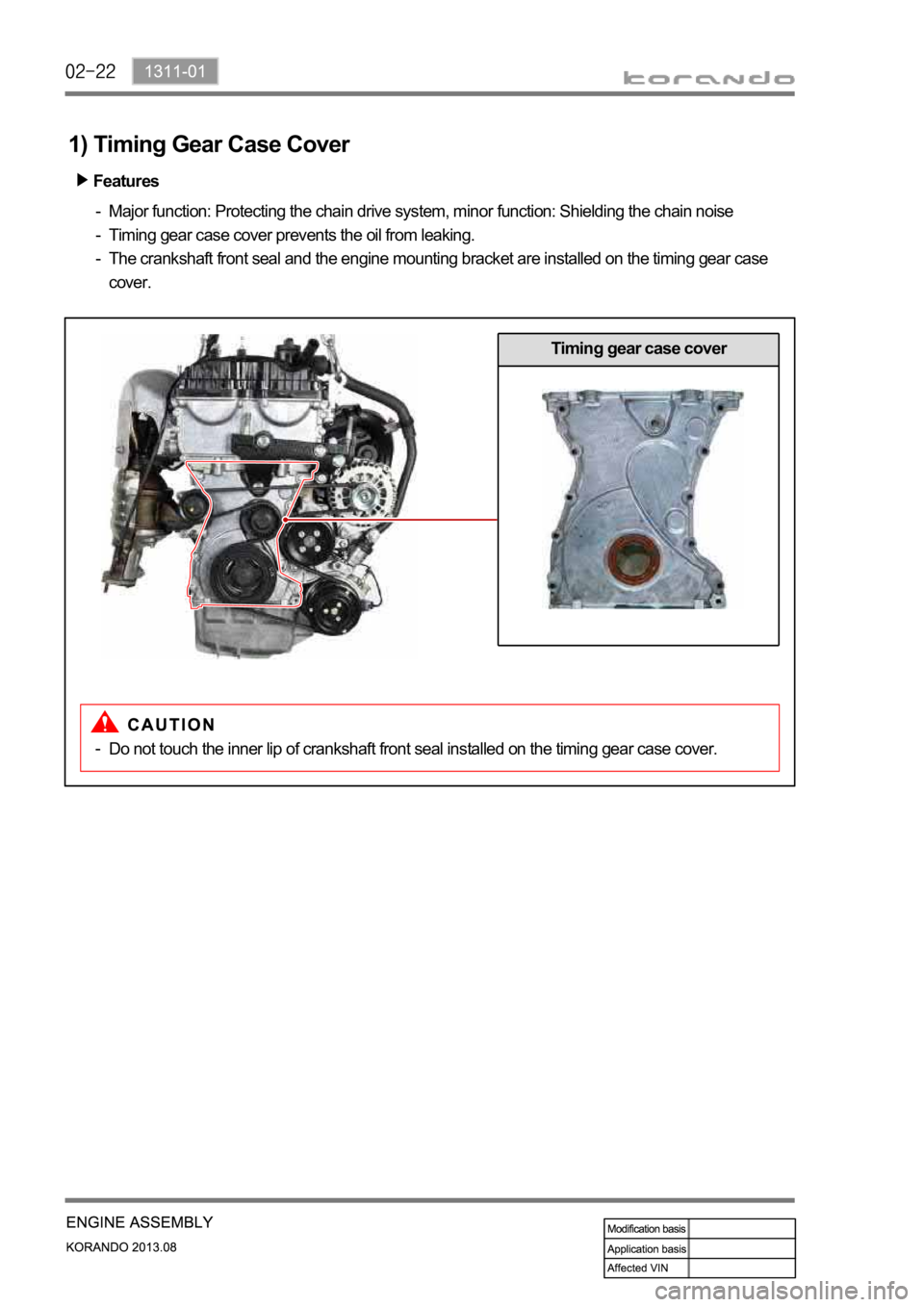
1) Timing Gear Case Cover
Features
Major function: Protecting the chain drive system, minor function: Shielding the chain noise
Timing gear case cover prevents the oil from leaking.
The crankshaft front seal and the engine mounting bracket are installed on the timing gear case
cover. -
-
-
Timing gear case cover
Do not touch the inner lip of crankshaft front seal installed on the timing gear case cover. -
Page 458 of 1336

1311-01
A. Timing chain
B. Oil pump chain
4) Timing Chain and Gear
Timing chain
Simple layout provides the optimized timing.
Decreased chain vibration and noise
Single stage layout: minimized chain load -
-
- Teeth: 146 ea
Teeth: 58 ea
Page 500 of 1336
1443-01
1. OVERVIEW
The ignition system is to supply high voltage generated from the ignition coil to the spark plug. The
G20DF engine is equipped with the independent type direct ignition system that the ignition coil is
installed in each cylinder.
The basic ignition timing in each cylinder is determined by the signals from camshaft position sensor and
crankshaft position sensor.
This ignition system controls the electronic ignition timing received from the engine ECU. To control the
ignition timing precisely, the ECU use the information below:
Engine load
Coolant temperature
Intake air temperature
Engine rpm
Camshaft position sensor (CPS)
Crankshaft position sensor (CKS) -
-
-
-
-
-
If the signal from the camshaft position sensor is not delivered to the engine ECU, the ignition coil and
fuel system cannot be operated.
Page 563 of 1336
1490-00
3. ECU CONTROL
1) Functions
ECU receives and analyzes signals from various sensors and then modifies those signals into
permissible voltage levels and analyzes to control respective actuators.
ECU microprocessor calculates injection period and injection timing proper for engine piston speed and
crankshaft angle based on input data and stored specific map to control the engine power and emission
gas.
Output signal of the ECU microprocessor activates the injector solenoid valve to control the fuel injection
period and injection timing; so controls various actuators in response to engine changes.
Auxiliary function of ECU has adopted to reduce emission gas, improve fuel economy and enhance
safety, comforts and conveniences. For example, there are autocruise and immobilizer and adopted
CAN communication to exchange data among electrical systems (automatic T/M and brake system) in
the vehicle fluently. And the diagnostic tool can be used to diagnose vehicle status and defectives.
water and electromagnetism and there should be no mechanical shocks.
2) Control Functions
Controls by operating stages:
To make optimum combustion under every operating stage, ECU should calculate proper injection
volume in each stage by considering various factors.
Starting injection volume control:
During initial starting, injecting fuel volume will be calculated by function of temperature and engine
cranking speed. Starting injection continues from when the ignition switch is turned to ignition
position to till the engine reaches to allowable minimum speed.
Driving mode control:
If the vehicle runs normally, fuel injection volume will be calculated by accelerator pedal travel and
engine rpm and the drive map will be used to match the drivers inputs with optimum engine power. -
-
-
Page 564 of 1336
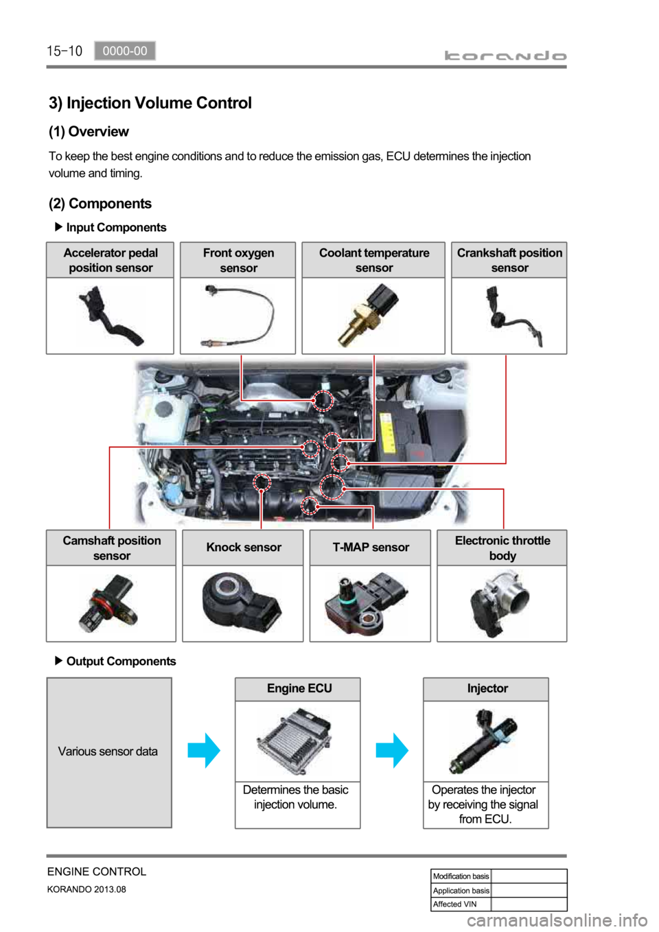
3) Injection Volume Control
(1) Overview
To keep the best engine conditions and to reduce the emission gas, ECU determines the injection
volume and timing.
(2) Components
Input Components
Accelerator pedal
position sensorFront oxygen
sensorCoolant temperature
sensorCrankshaft position
sensor
Camshaft position
sensorKnock sensorT-MAP sensorElectronic throttle
body
Output Components
Page 569 of 1336
0000-00
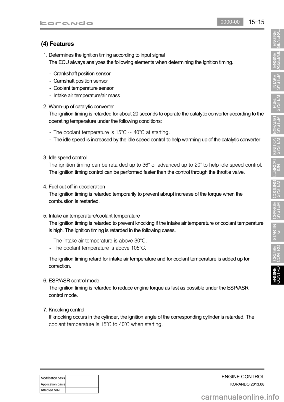
(4) Features
Determines the ignition timing according to input signal
The ECU always analyzes the following elements when determining the ignition timing. 1.
Crankshaft position sensor
Camshaft position sensor
Coolant temperature sensor
Intake air temperature/air mass -
-
-
-
Warm-up of catalytic converter
The ignition timing is retarded for about 20 seconds to operate the catalytic converter according to the
operating temperature under the following conditions: 2.
The idle speed is increased by the idle speed control to help warming up of the catalytic converter -
-
Idle speed control
The ignition timing control can be performed faster than the control through the throttle valve.
Fuel cut-off in deceleration
The ignition timing is retarded temporarily to prevent abrupt increase of the torque when the
combustion is restarted.
Intake air temperature/coolant temperature
The ignition timing is retarded to prevent knocking if the intake air temperature or coolant temperature
is high. The ignition timing is retarded in the following cases. 3.
4.
5.
-
-
The ignition timing retard for intake air temperature and for coolant temperature is added up for
correction.
ESP/ASR control mode
The ignition timing is retarded to reduce engine torque as fast as possible under the ESP/ASR
control mode.
Knocking control
If knocking occurs in the cylinder, the ignition angle of the corresponding cylinder is retarded. The
6.
7.