tow SSANGYONG KORANDO 2013 User Guide
[x] Cancel search | Manufacturer: SSANGYONG, Model Year: 2013, Model line: KORANDO, Model: SSANGYONG KORANDO 2013Pages: 1336, PDF Size: 92.18 MB
Page 875 of 1336
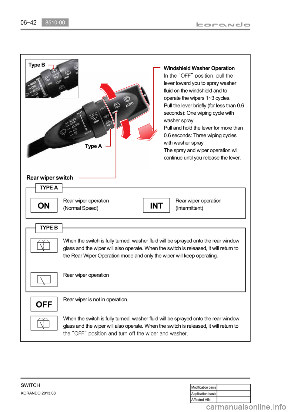
Rear wiper switch
Type B
Type AWindshield Washer Operation
lever toward you to spray washer
fluid on the windshield and to
operate the wipers 1~3 cycles.
Pull the lever briefly (for less than 0.6
seconds): One wiping cycle with
washer spray
Pull and hold the lever for more than
0.6 seconds: Three wiping cycles
with washer spray
The spray and wiper operation will
continue until you release the lever.
TYPE B
When the switch is fully turned, washer fluid will be sprayed onto the rear window
glass and the wiper will also operate. When the switch is released, it will return to
Rear wiper is not in operation.
TYPE A
INT
Rear wiper operation
(Intermittent)
ON
Rear wiper operation
(Normal Speed)
Rear wiper operation
When the switch is fully turned, washer fluid will be sprayed onto the rear window
glass and the wiper will also operate. When the switch is released, it will return to
the Rear Wiper Operation mode and only the wiper will keep operating.
Page 940 of 1336
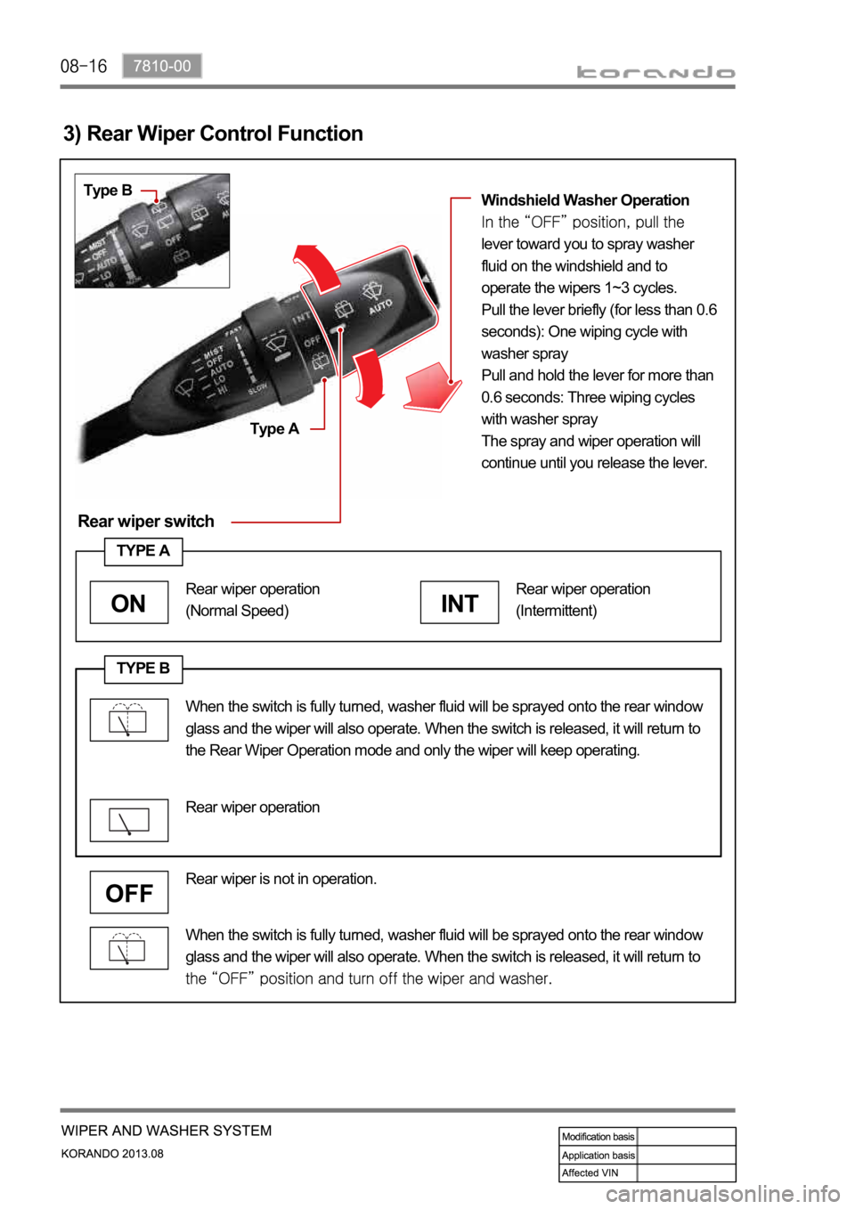
Rear wiper switch
3) Rear Wiper Control Function
Type B
Type AWindshield Washer Operation
lever toward you to spray washer
fluid on the windshield and to
operate the wipers 1~3 cycles.
Pull the lever briefly (for less than 0.6
seconds): One wiping cycle with
washer spray
Pull and hold the lever for more than
0.6 seconds: Three wiping cycles
with washer spray
The spray and wiper operation will
continue until you release the lever.
TYPE B
When the switch is fully turned, washer fluid will be sprayed onto the rear window
glass and the wiper will also operate. When the switch is released, it will return to
Rear wiper is not in operation.
TYPE A
INT
Rear wiper operation
(Intermittent)
ON
Rear wiper operation
(Normal Speed)
Rear wiper operation
When the switch is fully turned, washer fluid will be sprayed onto the rear window
glass and the wiper will also operate. When the switch is released, it will return to
the Rear Wiper Operation mode and only the wiper will keep operating.
Page 1009 of 1336

3680-01
2. FEATURES
1) Advantages
Early Downshift with Hard Braking and Skip Shifts
When heavy braking is detected, the transaxle downshifts early and skips gears to provide increased
engine braking to provide gear selection for tip-in.
Gear Hold going Uphill/Downhill
If the accelerator pedal is released when traveling uphill, upshifts are prevented to reduce busyness on
grades. If the accelerator pedal is released when traveling downhill, upshifts are prevented to enhance
engine braking.
Drive and Reverse Engagement
A soft engagement feature avoids harsh take up of drive when selecting Drive or Reverse. This is
achieved by limiting engine speed and engine torque which results in a rapid, but progressive
engagement of either Drive or Reverse when moving from the Park or Neutral positions. Drive and
Reverse engagements from either Park or Neutral are performed in less than 2.2 seconds. There is no
drive engagement prevention strategy implemented on the transaxle system as there is sufficient engine
strategy to protect the system. However, reverse engagement is prevented until engine speed is less
than 1,400 rpm and the accelerator pedal position is less than 12% and vehicle speed is less than 10
km/h.
Converter Clutch Lock-Up In All Gears
The transaxle features converter clutch lock-up in all gears. This feature provides improved fuel economy
and vehicle performance. It also improves transaxle cooling efficiency when towing heavy loads at low
speeds, e.g. in city driving or hill terrain.
Embedded Memory Module (EMM)
The embedded memory module (EMM) is
transaxle assembly to ensure refined shift quality.
The EMM is used to store data such as valve body
calibration data and valve body serial number.
Upon installation, the TCU will download the data
from the EMM and utilize this data in the operation
of the transaxle.
Page 1013 of 1336
3680-01
4. LIMP HOME MODE
When the transaxle is defective
In the event of a system fault, the TCU also provides for failure mode effect control (FMEC) to maintain
maximum functional operation of the transaxle.
In the event of a total loss of control or electrical power, the basic transaxle functions (Park, Reverse,
Neutral and Drive) are retained. The 4th and reverse gear ratios with the torque converter clutch in the
unlocked state are the retained gear states the hydraulic system supports without any electrical
assistance.
The TCU communicates with other vehicle electronic control modules by the controller area network
(CAN). If a major fault develops, the transaxle may automatically operate in a "limp home" (failure)
mode to enable the vehicle to be driven to an authorized dealer for repair.
The TCU also provides for transaxle diagnostics, which meet the requirements of OBD II legislation,
monitoring all components which may effect vehicle emissions. 1.
2.
3.
4.
When the transaxle overheats
Limp home mode may also be engaged if the battery charge falls below 8V.
If the transaxle overheats, the shift patterns will automatically change to enable improved transaxle
cooling.
During transaxle overheat, the instrument cluster transaxle selector position display and the over
cluster until normal transaxle operating temperature is reached. 1.
2.
3.
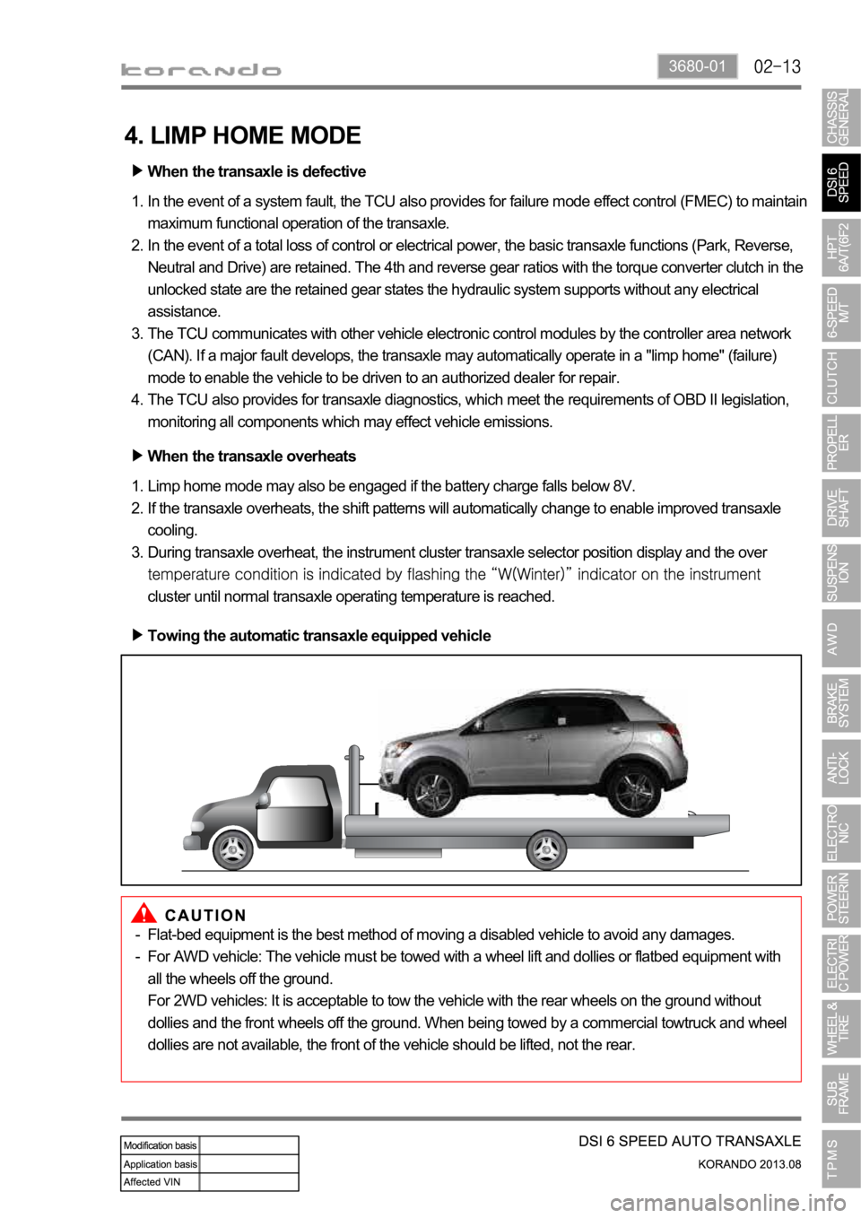
Towing the automatic transaxle equipped vehicle
Flat-bed equipment is the best method of moving a disabled vehicle to avoid any damages.
For AWD vehicle: The vehicle must be towed with a wheel lift and dollies or flatbed equipment with
all the wheels off the ground.
For 2WD vehicles: It is acceptable to tow the vehicle with the rear wheels on the ground without
dollies and the front wheels off the ground. When being towed by a commercial towtruck and wheel
dollies are not available, the front of the vehicle should be lifted, not the rear. -
-
Page 1042 of 1336
4. LIMP HOME MODE
When the transaxle is defective
In the event of a system fault, the TCU also provides for failure mode effect control (FMEC) to maintain
maximum functional operation of the transaxle. (There are 3 FMEC modes, mechanical limp-home
mode, electrical limp-home mode, limp-home mode C.)
In the event of a total loss of control or electrical power, the basic transaxle functions (Park, Reverse,
Neutral and Drive) are retained. The 4th and reverse gear ratios with the torque converter clutch in the
unlocked state are the retained gear states the hydraulic system supports without any electrical
assistance. (Mechanical limp-home)
If the speed sensor circuit is failed, the gear is fixed to 4th gear, but manual shifting
If the inhibitor switch signals are invalid, shifting to1st and 2nd gear is forbidden. (Limp-home C)
The TCU communicates with other vehicle electronic control modules by the controller area network
(CAN). If a major fault is developed, the transaxle may not accomplish the intelligent shift control. The
TCU controls the transaxle with preset values.
The TCU also provides for transaxle diagnostics, which meet the requirements of OBD II regulation,
monitoring all components which may effect vehicle emissions. 1.
2.
3.
4.
5.
6.
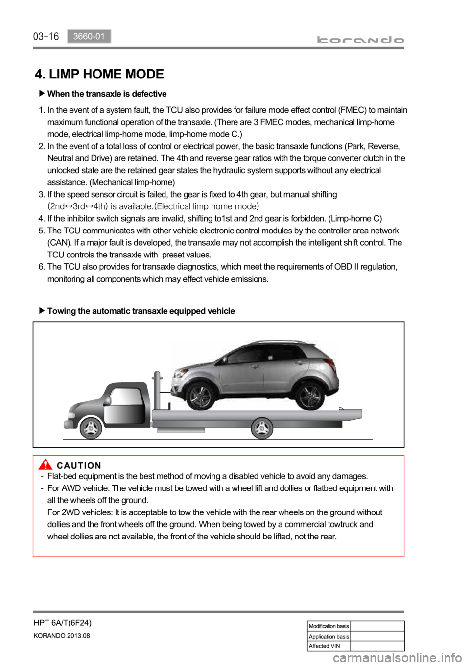
Towing the automatic transaxle equipped vehicle
Flat-bed equipment is the best method of moving a disabled vehicle to avoid any damages.
For AWD vehicle: The vehicle must be towed with a wheel lift and dollies or flatbed equipment with
all the wheels off the ground.
For 2WD vehicles: It is acceptable to tow the vehicle with the rear wheels on the ground without
dollies and the front wheels off the ground. When being towed by a commercial towtruck and
wheel dollies are not available, the front of the vehicle should be lifted, not the rear. -
-
Page 1128 of 1336
0000-00
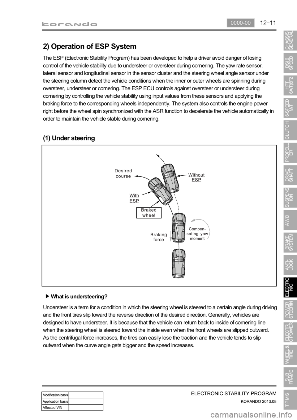
2) Operation of ESP System
The ESP (Electronic Stability Program) has been developed to help a driver avoid danger of losing
control of the vehicle stability due to understeer or oversteer during cornering. The yaw rate sensor,
lateral sensor and longitudinal sensor in the sensor cluster and the steering wheel angle sensor under
the steering column detect the vehicle conditions when the inner or outer wheels are spinning during
oversteer, understeer or cornering. The ESP ECU controls against oversteer or understeer during
cornering by controlling the vehicle stability using input values from these sensors and applying the
braking force to the corresponding wheels independently. The system also controls the engine power
right before the wheel spin synchronized with the ASR function to decelerate the vehicle automatically in
order to maintain the vehicle stable during cornering.
(1) Under steering
What is understeering?
Understeer is a term for a condition in which the steering wheel is steered to a certain angle during driving
and the front tires slip toward the reverse direction of the desired direction. Generally, vehicles are
designed to have understeer. It is because that the vehicle can return back to inside of cornering line
when the steering wheel is steered toward the inside even when the front wheels are slipped outward.
As the centrifugal force increases, the tires can easily lose the traction and the vehicle tends to slip
outward when the curve angle gets bigger and the speed increases.
Page 1129 of 1336
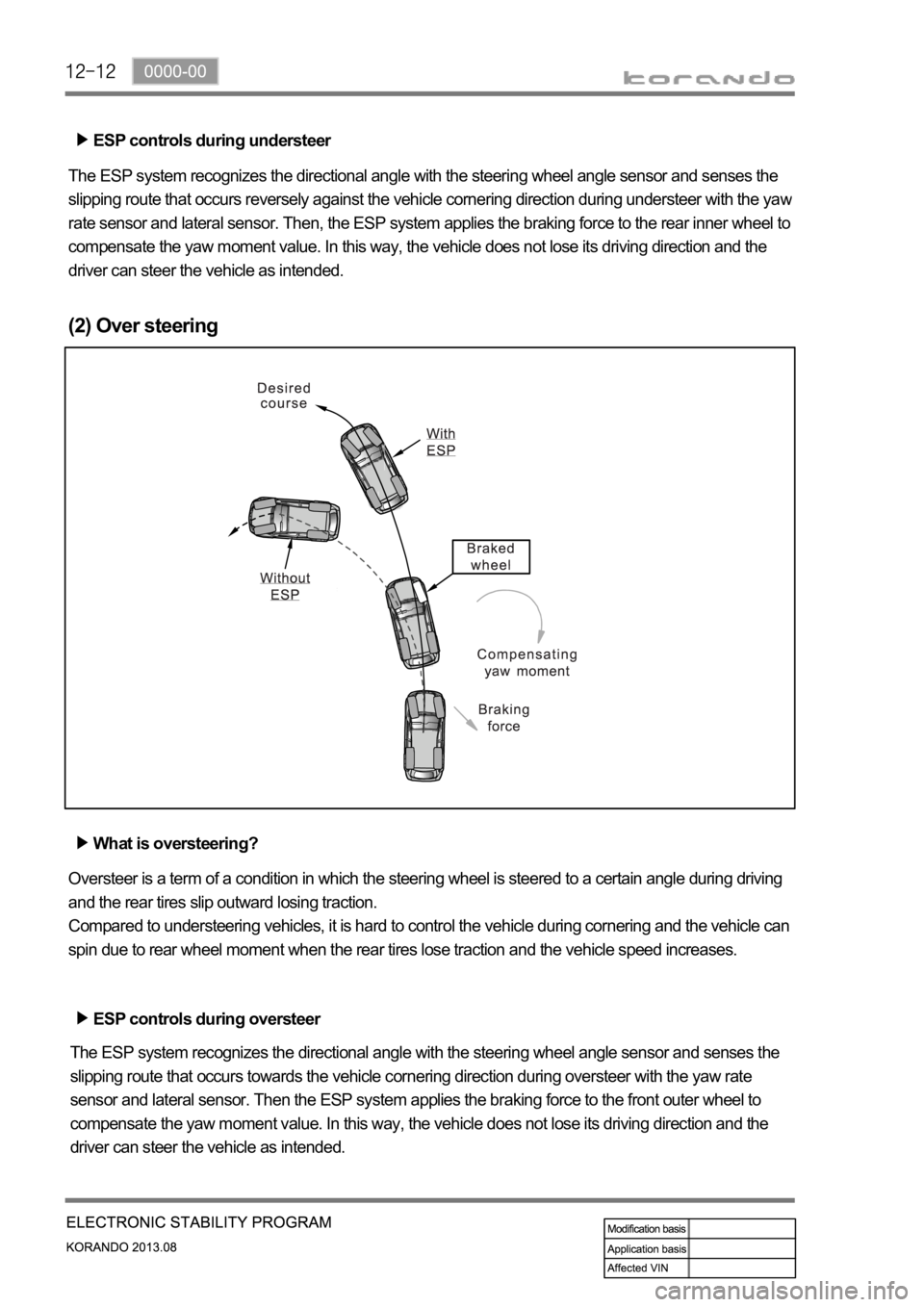
ESP controls during understeer
The ESP system recognizes the directional angle with the steering wheel angle sensor and senses the
slipping route that occurs reversely against the vehicle cornering direction during understeer with the ya
w
rate sensor and lateral sensor. Then, the ESP system applies the braking force to the rear inner wheel to
compensate the yaw moment value. In this way, the vehicle does not lose its driving direction and the
driver can steer the vehicle as intended.
(2) Over steering
What is oversteering?
Oversteer is a term of a condition in which the steering wheel is steered to a certain angle during driving
and the rear tires slip outward losing traction.
Compared to understeering vehicles, it is hard to control the vehicle during cornering and the vehicle can
spin due to rear wheel moment when the rear tires lose traction and the vehicle speed increases.
ESP controls during oversteer
The ESP system recognizes the directional angle with the steering wheel angle sensor and senses the
slipping route that occurs towards the vehicle cornering direction during oversteer with the yaw rate
sensor and lateral sensor. Then the ESP system applies the braking force to the front outer wheel to
compensate the yaw moment value. In this way, the vehicle does not lose its driving direction and the
driver can steer the vehicle as intended.
Page 1229 of 1336
3. CAUTIONS FOR AIR BAG SYSTEM
Cautions for air bag maintenance
Whenever installing or removing the devices related to the air bag system, disconnect the negative
battery cable and wait for at least 30 seconds.
Do not connect a tester probe to the inflator to measure the resistance of the component of the air
bag system. The detonator of the inflator may explode due to a sudden extra power supplied by the
tester.
Note that the used components related to the air bag system, especially the air bag unit, should be
packed in an air tight container and prevent it from any impact or damage.
When there is any deployed air bag (including curtain air bag and seat belt pretensioner), the entire
system including the air bag unit should be replaced. The deployed air bag unit should not be reused
since it has status data when it is deployed, and the data cannot be cleared with a diagnostic device.
The air bag and seat belt pretensioner systems contain explosive charges, so handle carefully when
disposing or replacing them. 1.
2.
3.
4.
5.
Cautions for air bag maintenance
Do not modify, change or apply impact on any air bag component. The air bag may be deployed
abruptly, causing serious injuries.
Children and infants should ride in a rear seat. Seating in the passenger seat with carrying a
child or infant is strictly prohibited. An infant or a child could be severely injured by the air bag
deployment.
A child restraint system must not be installed on the front seat. An infant or a child could be severely
injured by the air bag deployment when it is fitted to the passenger seat.
Do not place any objects on the air bag inflation location. You may get injured by those objects during
deployment.
Never put your arms around the front seat from behind, lean on the front seatback, or put your arms
out of the window. You can severely injured when the side air bag deploys.
Never lean on the door since it becomes very dangerous when the side air bag deploys.
The side air bag deploys when there is a severe side collision.
Do not slam the front door to close it. The side air bag may deploy unexpectedly.
When an occupant fastens the seat belt in an unstable or inclined posture, the air bag system cannot
protect the occupant properly. Moreover, the occupant can be injured by the air bag.
Do not move your seat too close to the steering wheel or dashboard. Being too close to the
steering wheel or instrument panel during the air bag deployment could cause serious injury,
including death
Hold only the outer rim of the steering so that the air bag can inflate without any hindrance.
Do not incline toward the steering wheel. Never allow the passenger to put hands or feet on the dash
board. The air bag cannot work properly Do not hold and operate the steering wheel by crossing your
arms You could get seriously injured when the air bag deploys. 1.
2.
3.
4.
5.
6.
7.
8.
9.
10.
11.
Page 1270 of 1336

7410-00
(3) Operating process
Driver seat
Passenger seat
For a vehicle with an active head restraint system, an active head restraint sensor is installed and its G
sensor is operated in the event of a rear-end collision. As the G sensor in the active head restraint
sensor is operated, the power is supplied to the driver's or passenger's active head restraint. Then, the
lock in the head restraint is disengaged and the front part of the head restraint is separated and moved
toward the neck of an occupant.