Start stop SSANGYONG KORANDO 2013 Service Manual
[x] Cancel search | Manufacturer: SSANGYONG, Model Year: 2013, Model line: KORANDO, Model: SSANGYONG KORANDO 2013Pages: 1336, PDF Size: 92.18 MB
Page 272 of 1336
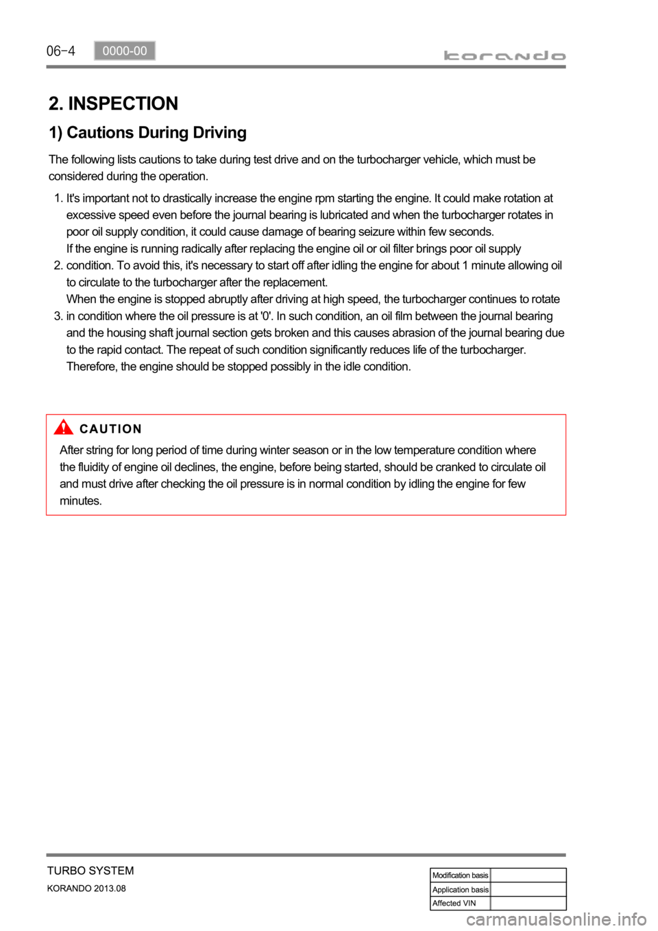
2. INSPECTION
1) Cautions During Driving
The following lists cautions to take during test drive and on the turbocharger vehicle, which must be
considered during the operation.
It's important not to drastically increase the engine rpm starting the engine. It could make rotation at
excessive speed even before the journal bearing is lubricated and when the turbocharger rotates in
poor oil supply condition, it could cause damage of bearing seizure within few seconds.
If the engine is running radically after replacing the engine oil or oil filter brings poor oil supply
condition. To avoid this, it's necessary to start off after idling the engine for about 1 minute allowing oil
to circulate to the turbocharger after the replacement.
When the engine is stopped abruptly after driving at high speed, the turbocharger continues to rotate
in condition where the oil pressure is at '0'. In such condition, an oil film between the journal bearing
and the housing shaft journal section gets broken and this causes abrasion of the journal bearing due
to the rapid contact. The repeat of such condition significantly reduces life of the turbocharger.
Therefore, the engine should be stopped possibly in the idle condition. 1.
2.
3.
After string for long period of time during winter season or in the low temperature condition where
the fluidity of engine oil declines, the engine, before being started, should be cranked to circulate oil
and must drive after checking the oil pressure is in normal condition by idling the engine for few
minutes.
Page 309 of 1336
0000-00
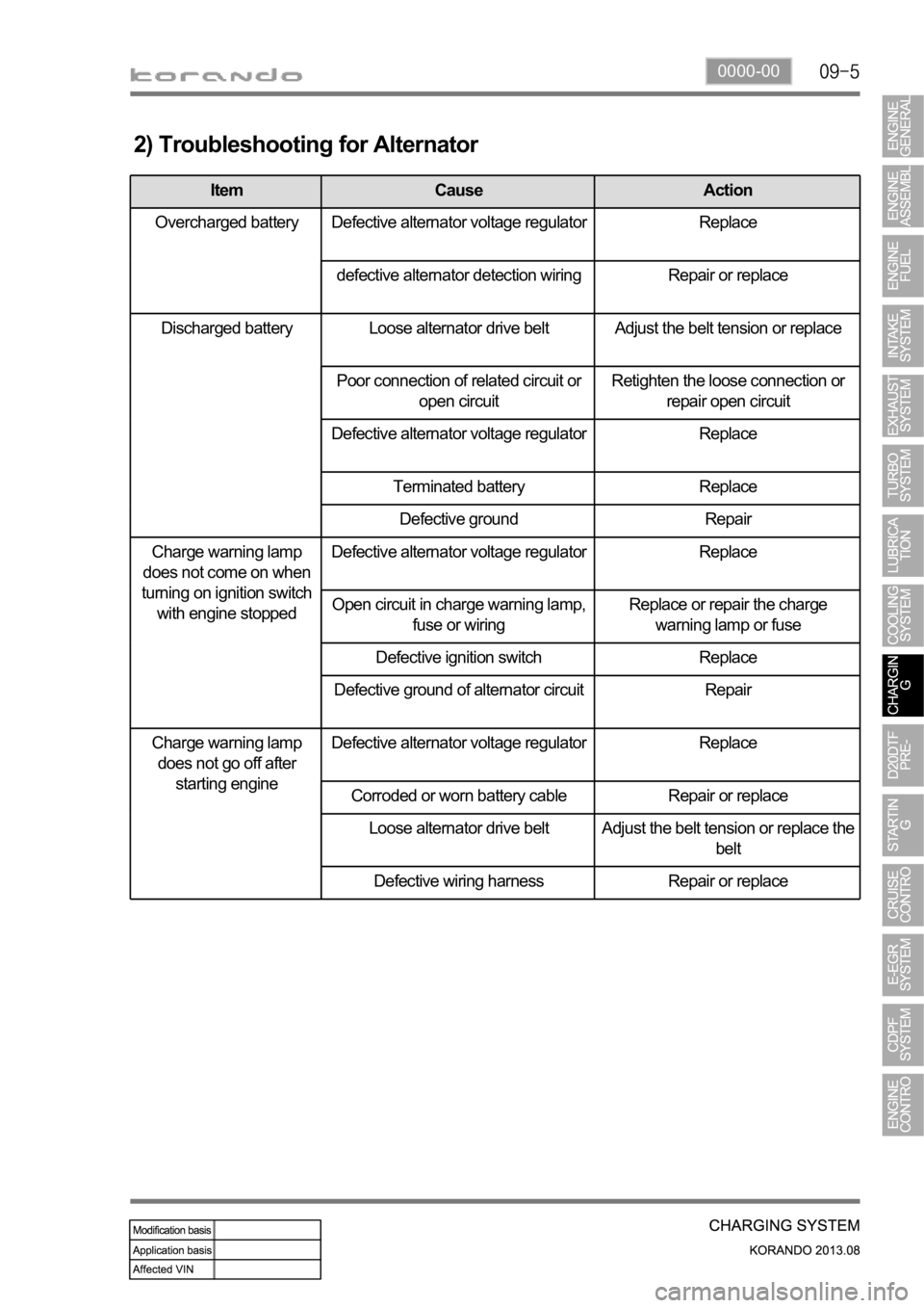
2) Troubleshooting for Alternator
Item Cause Action
Overcharged battery Defective alternator voltage regulator Replace
defective alternator detection wiring Repair or replace
Discharged battery Loose alternator drive belt Adjust the belt tension or replace
Poor connection of related circuit or
open circuitRetighten the loose connection or
repair open circuit
Defective alternator voltage regulator Replace
Terminated battery Replace
Defective ground Repair
Charge warning lamp
does not come on when
turning on ignition switch
with engine stoppedDefective alternator voltage regulator Replace
Open circuit in charge warning lamp,
fuse or wiringReplace or repair the charge
warning lamp or fuse
Defective ignition switch Replace
Defective ground of alternator circuit Repair
Charge warning lamp
does not go off after
starting engineDefective alternator voltage regulator Replace
Corroded or worn battery cable Repair or replace
Loose alternator drive belt
Adjust the belt tension or replace the
belt
Defective wiring harness Repair or replace
Page 333 of 1336
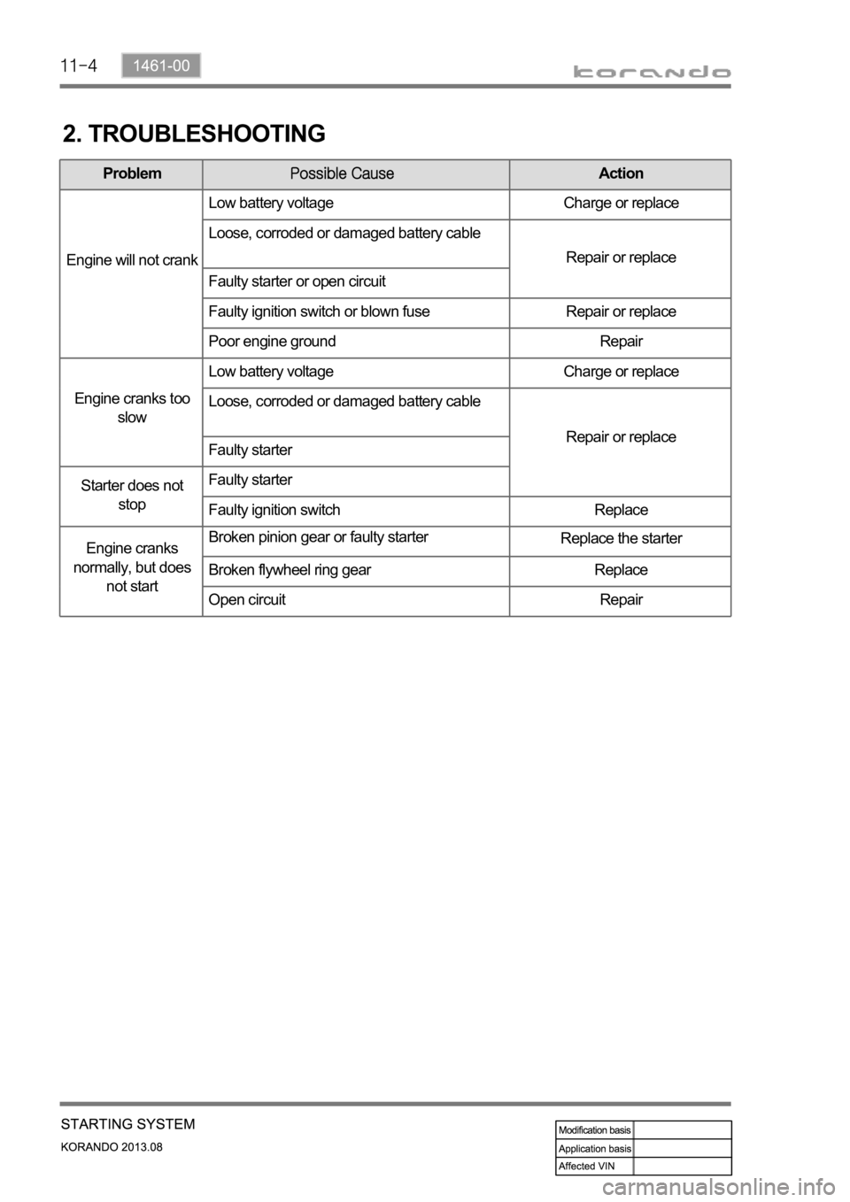
2. TROUBLESHOOTING
ProblemAction
Engine will not crankLow battery voltage Charge or replace
Loose, corroded or damaged battery cable
Repair or replace
Faulty starter or open circuit
Faulty ignition switch or blown fuse Repair or replace
Poor engine ground Repair
Engine cranks too
slowLow battery voltage Charge or replace
Loose, corroded or damaged battery cable
Repair or replace
Faulty starter
Starter does not
stopFaulty starter
Faulty ignition switch Replace
Engine cranks
normally, but does
not startBroken pinion gear or faulty starter
Replace the starter
Broken flywheel ring gear Replace
Open circuit Repair
Page 335 of 1336
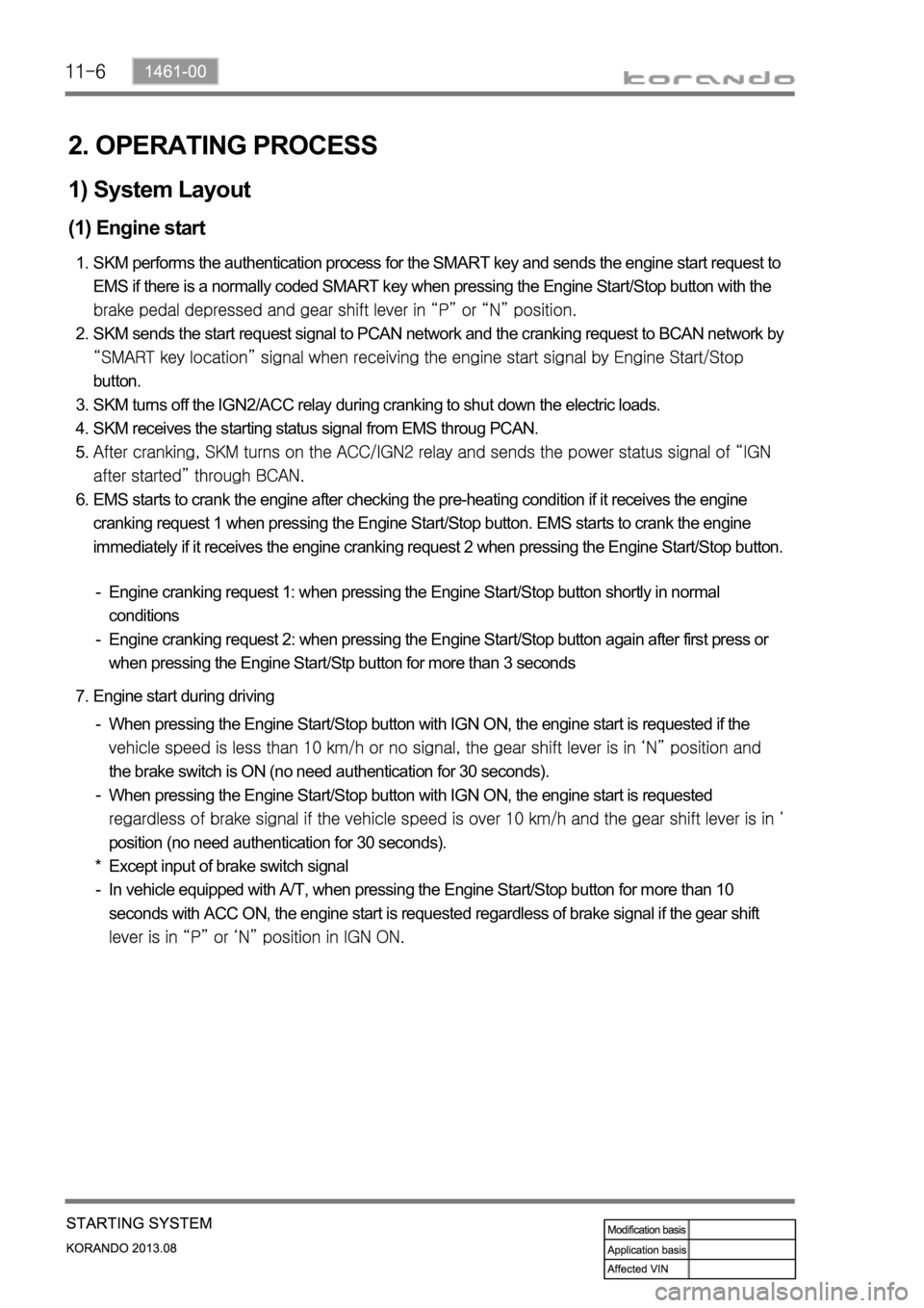
2. OPERATING PROCESS
1) System Layout
(1) Engine start
SKM performs the authentication process for the SMART key and sends the engine start request to
EMS if there is a normally coded SMART key when pressing the Engine Start/Stop button with the
SKM sends the start request signal to PCAN network and the cranking request to BCAN network by
button.
SKM turns off the IGN2/ACC relay during cranking to shut down the electric loads.
SKM receives the starting status signal from EMS throug PCAN.
EMS starts to crank the engine after checking the pre-heating condition if it receives the engine
cranking request 1 when pressing the Engine Start/Stop button. EMS starts to crank the engine
immediately if it receives the engine cranking request 2 when pressing the Engine Start/Stop button. 1.
2.
3.
4.
5.
6.
Engine cranking request 1: when pressing the Engine Start/Stop button shortly in normal
conditions
Engine cranking request 2: when pressing the Engine Start/Stop button again after first press or
when pressing the Engine Start/Stp button for more than 3 seconds -
-
Engine start during driving 7.
When pressing the Engine Start/Stop button with IGN ON, the engine start is requested if the
the brake switch is ON (no need authentication for 30 seconds).
When pressing the Engine Start/Stop button with IGN ON, the engine start is requested
position (no need authentication for 30 seconds).
Except input of brake switch signal
In vehicle equipped with A/T, when pressing the Engine Start/Stop button for more than 10
seconds with ACC ON, the engine start is requested regardless of brake signal if the gear shift
-
-
*
-
Page 373 of 1336
1114-00
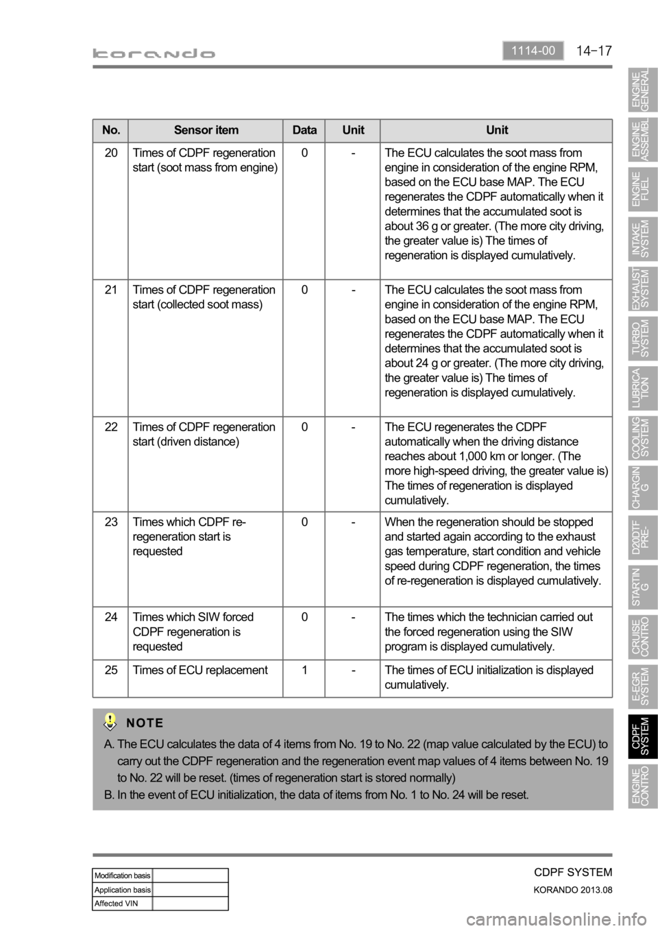
No. Sensor item Data Unit Unit
20 Times of CDPF regeneration
start (soot mass from engine)0 - The ECU calculates the soot mass from
engine in consideration of the engine RPM,
based on the ECU base MAP. The ECU
regenerates the CDPF automatically when it
determines that the accumulated soot is
about 36 g or greater. (The more city driving,
the greater value is) The times of
regeneration is displayed cumulatively.
21 Times of CDPF regeneration
start (collected soot mass)0 - The ECU calculates the soot mass from
engine in consideration of the engine RPM,
based on the ECU base MAP. The ECU
regenerates the CDPF automatically when it
determines that the accumulated soot is
about 24 g or greater. (The more city driving,
the greater value is) The times of
regeneration is displayed cumulatively.
22 Times of CDPF regeneration
start (driven distance)0 - The ECU regenerates the CDPF
automatically when the driving distance
reaches about 1,000 km or longer. (The
more high-speed driving, the greater value is)
The times of regeneration is displayed
cumulatively.
23 Times which CDPF re-
regeneration start is
requested0 - When the regeneration should be stopped
and started again according to the exhaust
gas temperature, start condition and vehicle
speed during CDPF regeneration, the times
of re-regeneration is displayed cumulatively.
24 Times which SIW forced
CDPF regeneration is
requested0 - The times which the technician carried out
the forced regeneration using the SIW
program is displayed cumulatively.
25 Times of ECU replacement 1 - The times of ECU initialization is displayed
cumulatively.
The ECU calculates the data of 4 items from No. 19 to No. 22 (map value calculated by the ECU) to
carry out the CDPF regeneration and the regeneration event map values of 4 items between No. 19
to No. 22 will be reset. (times of regeneration start is stored normally)
In the event of ECU initialization, the data of items from No. 1 to No. 24 will be reset. A.
B.
Page 414 of 1336
0000-00
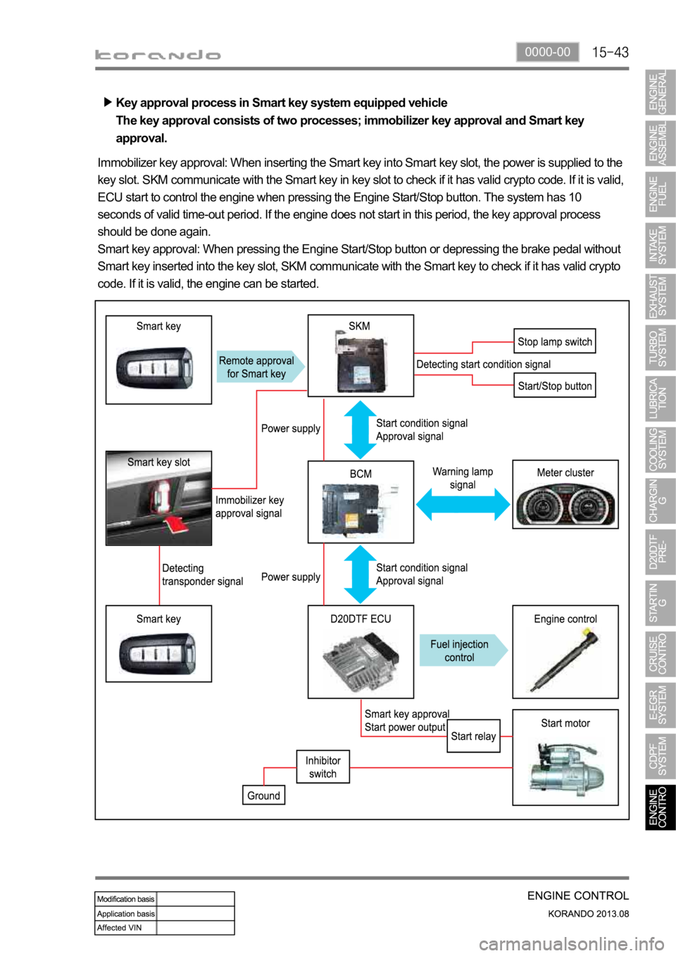
Key approval process in Smart key system equipped vehicle
The key approval consists of two processes; immobilizer key approval and Smart key
approval.
Immobilizer key approval: When inserting the Smart key into Smart key slot, the power is supplied to the
key slot. SKM communicate with the Smart key in key slot to check if it has valid crypto code. If it is valid,
ECU start to control the engine when pressing the Engine Start/Stop button. The system has 10
seconds of valid time-out period. If the engine does not start in this period, the key approval process
should be done again.
Smart key approval: When pressing the Engine Start/Stop button or depressing the brake pedal without
Smart key inserted into the key slot, SKM communicate with the Smart key to check if it has valid crypto
code. If it is valid, the engine can be started.
Page 440 of 1336
1116-01
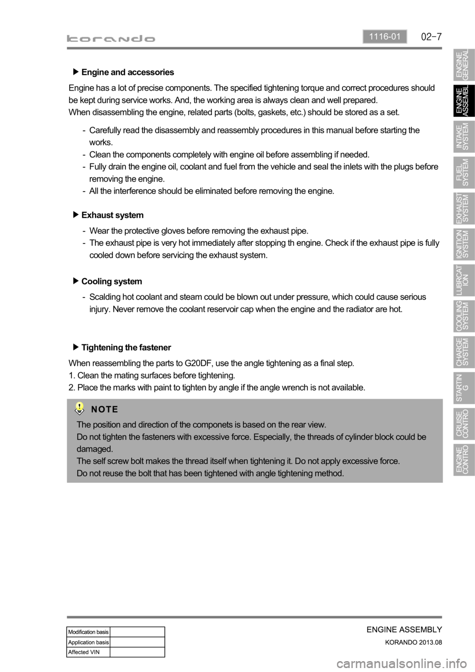
Engine and accessories
Engine has a lot of precise components. The specified tightening torque and correct procedures should
be kept during service works. And, the working area is always clean and well prepared.
When disassembling the engine, related parts (bolts, gaskets, etc.) should be stored as a set.
Carefully read the disassembly and reassembly procedures in this manual before starting the
works.
Clean the components completely with engine oil before assembling if needed.
Fully drain the engine oil, coolant and fuel from the vehicle and seal the inlets with the plugs before
removing the engine.
All the interference should be eliminated before removing the engine. -
-
-
-
Tightening the fastener
When reassembling the parts to G20DF, use the angle tightening as a final step.
1. Clean the mating surfaces before tightening.
2. Place the marks with paint to tighten by angle if the angle wrench is not available. Exhaust system
Wear the protective gloves before removing the exhaust pipe.
The exhaust pipe is very hot immediately after stopping th engine. Check if the exhaust pipe is fully
cooled down before servicing the exhaust system. -
-
Cooling system
Scalding hot coolant and steam could be blown out under pressure, which could cause serious
injury. Never remove the coolant reservoir cap when the engine and the radiator are hot. -
The position and direction of the componets is based on the rear view.
Do not tighten the fasteners with excessive force. Especially, the threads of cylinder block could be
damaged.
The self screw bolt makes the thread itself when tightening it. Do not apply excessive force.
Do not reuse the bolt that has been tightened with angle tightening method.
Page 530 of 1336
1452-01
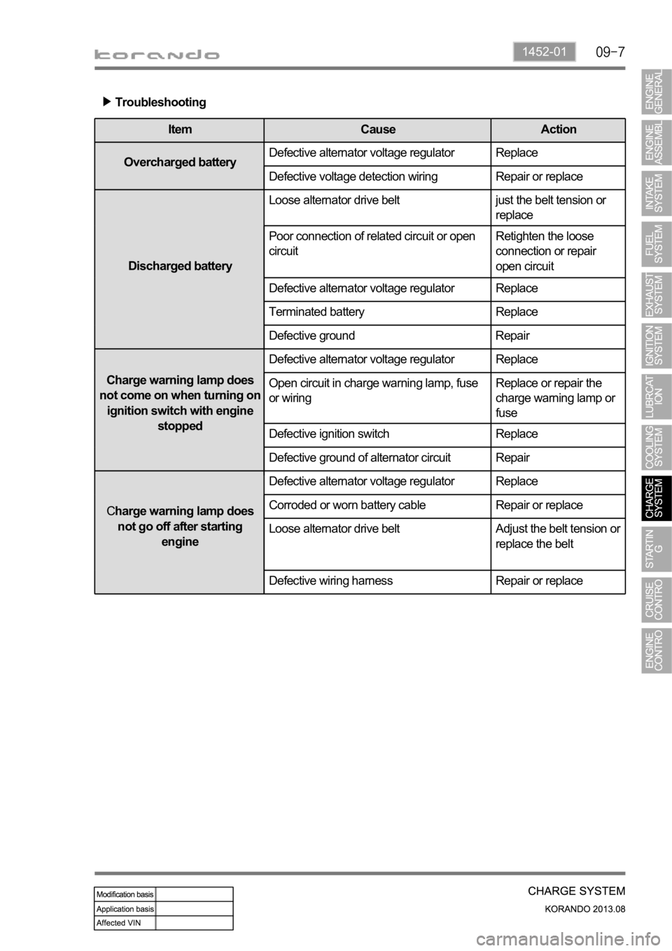
Troubleshooting
Item Cause Action
Overcharged batteryDefective alternator voltage regulator Replace
Defective voltage detection wiring Repair or replace
Discharged batteryLoose alternator drive belt
just the belt tension or
replace
Poor connection of related circuit or open
circuitRetighten the loose
connection or repair
open circuit
Defective alternator voltage regulator Replace
Terminated battery Replace
Defective ground Repair
Charge warning lamp does
not come on when turning on
ignition switch with engine
stoppedDefective alternator voltage regulator Replace
Open circuit in charge warning lamp, fuse
or wiringReplace or repair the
charge warning lamp or
fuse
Defective ignition switch Replace
Defective ground of alternator circuit Repair
Charge warning lamp does
not go off after starting
engineDefective alternator voltage regulator Replace
Corroded or worn battery cable Repair or replace
Loose alternator drive belt
Adjust the belt tension or
replace the belt
Defective wiring harness Repair or replace
Page 541 of 1336
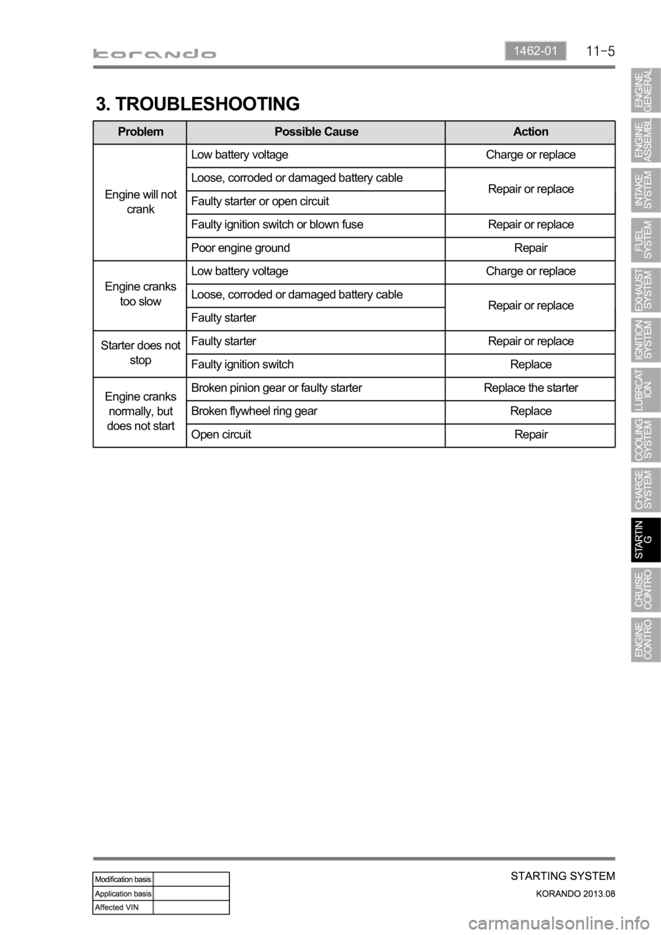
1462-01
3. TROUBLESHOOTING
Problem Possible Cause Action
Engine will not
crankLow battery voltage Charge or replace
Loose, corroded or damaged battery cable
Repair or replace
Faulty starter or open circuit
Faulty ignition switch or blown fuse Repair or replace
Poor engine ground Repair
Engine cranks
too slowLow battery voltage Charge or replace
Loose, corroded or damaged battery cable
Repair or replace
Faulty starter
Starter does not
stopFaulty starter Repair or replace
Faulty ignition switch Replace
Engine cranks
normally, but
does not startBroken pinion gear or faulty starter Replace the starter
Broken flywheel ring gear Replace
Open circuit Repair
Page 620 of 1336
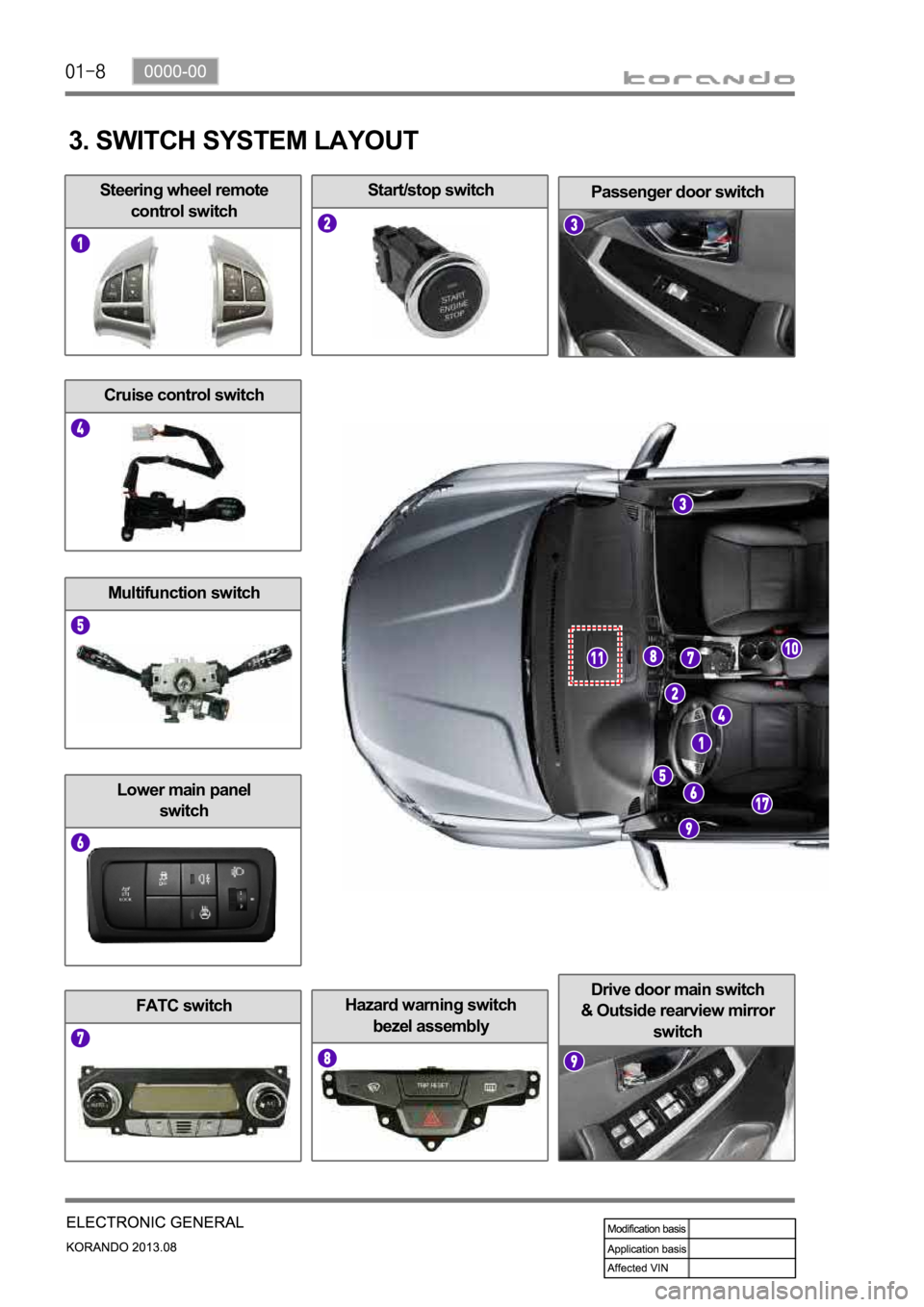
Hazard warning switch
bezel assembly
Drive door main switch
& Outside rearview mirror
switch
FATC switch
Steering wheel remote
control switchPassenger door switch
Lower main panel
switch
Start/stop switch
Cruise control switch
Multifunction switch
3. SWITCH SYSTEM LAYOUT