brake sensor SSANGYONG KORANDO 2013 Service Manual
[x] Cancel search | Manufacturer: SSANGYONG, Model Year: 2013, Model line: KORANDO, Model: SSANGYONG KORANDO 2013Pages: 1336, PDF Size: 92.18 MB
Page 374 of 1336
0000-00
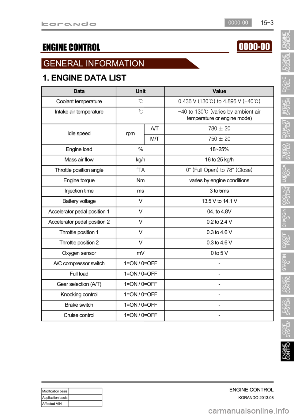
1. ENGINE DATA LIST
Data Unit Value
Coolant temperature
Intake air temperature
temperature or engine mode)
Idle speed rpmA/T
M/T
Engine load % 18~25%
Mass air flow kg/h 16 to 25 kg/h
Throttle position angle
Engine torque Nm varies by engine conditions
Injection time ms 3 to 5ms
Battery voltage V 13.5 V to 14.1 V
Accelerator pedal position 1 V 04. to 4.8V
Accelerator pedal position 2 V 0.2 to 2.4 V
Throttle position 1 V 0.3 to 4.6 V
Throttle position 2 V 0.3 to 4.6 V
Oxygen sensor mV 0 to 5 V
A/C compressor switch 1=ON / 0=OFF -
Full load 1=ON / 0=OFF -
Gear selection (A/T) 1=ON / 0=OFF -
Knocking control 1=ON / 0=OFF -
Brake switch 1=ON / 0=OFF -
Cruise control 1=ON / 0=OFF -
Page 378 of 1336
0000-00
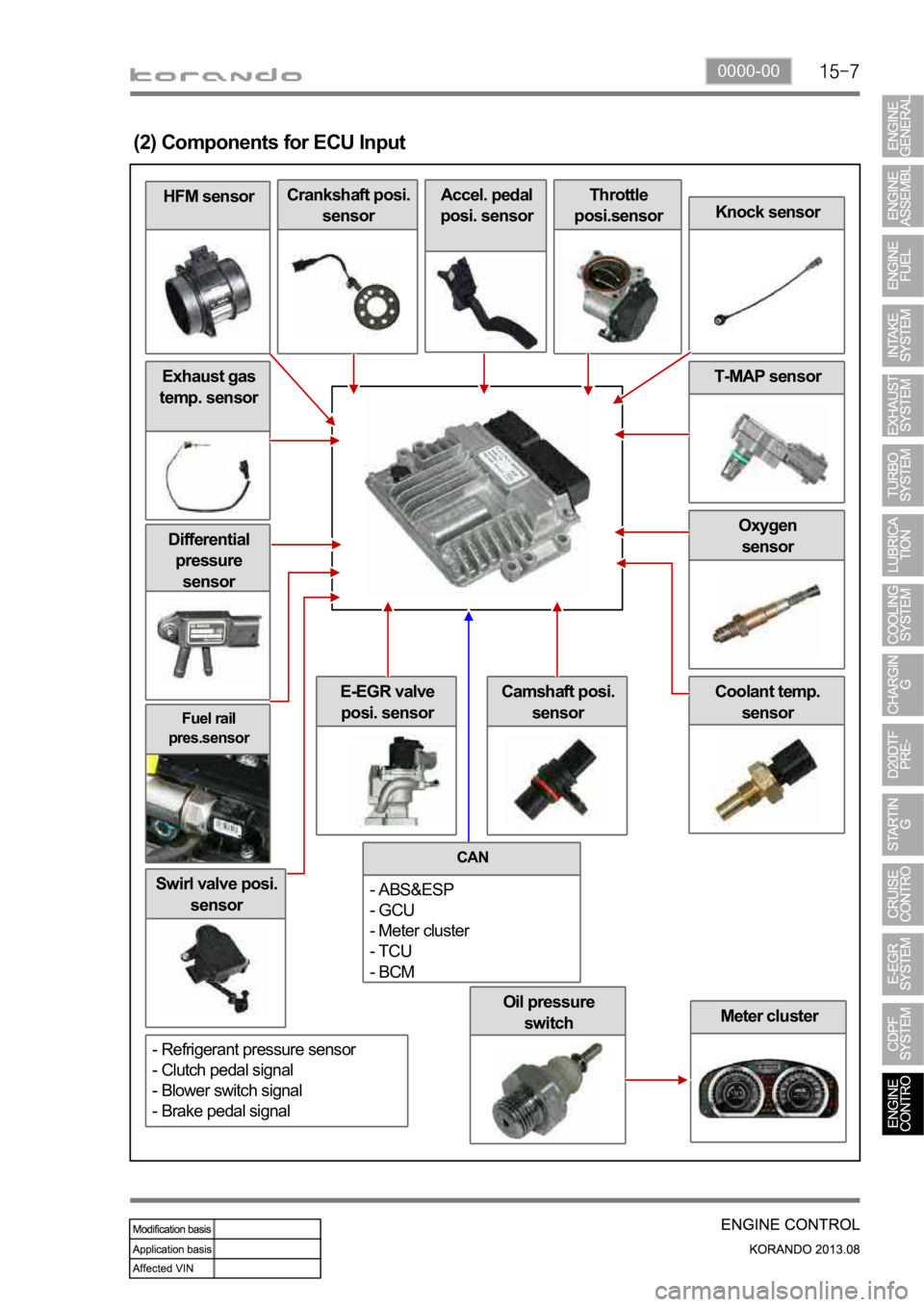
Oil pressure
switch
Fuel rail
pres.sensor
Differential
pressure
sensor
Swirl valve posi.
sensor
Meter cluster
Coolant temp.
sensorE-EGR valve
posi. sensor
Oxygen
sensor
Exhaust gas
temp. sensor
HFM sensor
(2) Components for ECU Input
Crankshaft posi.
sensorAccel. pedal
posi. sensorThrottle
posi.sensor
Knock sensor
T-MAP sensor
Camshaft posi.
sensor
CAN
- ABS&ESP
- GCU
- Meter cluster
- TCU
- BCM
- Refrigerant pressure sensor
- Clutch pedal signal
- Blower switch signal
- Brake pedal signal
Page 380 of 1336
0000-00
2) ECU Control
(1) Function
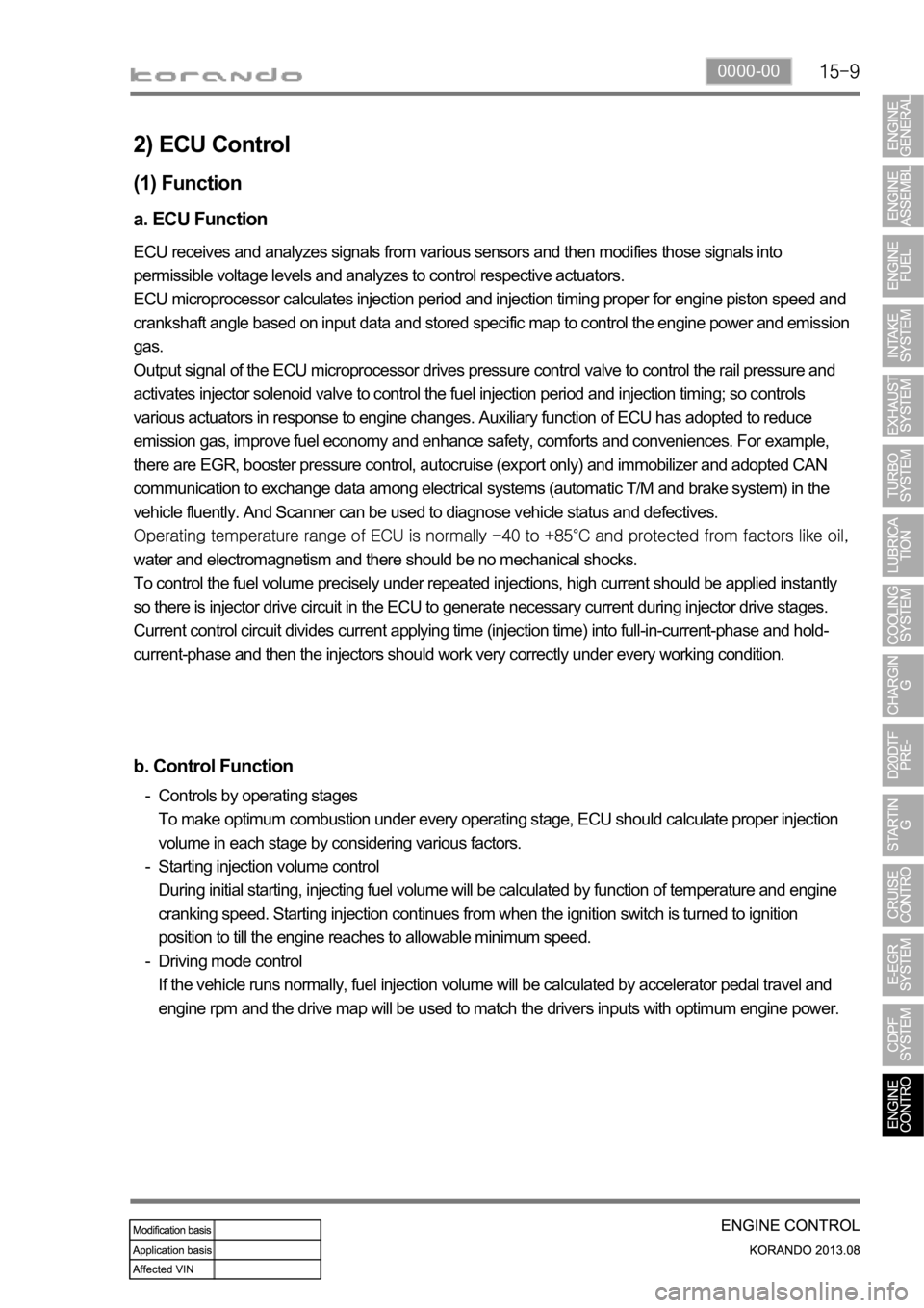
a. ECU Function
ECU receives and analyzes signals from various sensors and then modifies those signals into
permissible voltage levels and analyzes to control respective actuators.
ECU microprocessor calculates injection period and injection timing proper for engine piston speed and
crankshaft angle based on input data and stored specific map to control the engine power and emission
gas.
Output signal of the ECU microprocessor drives pressure control valve to control the rail pressure and
activates injector solenoid valve to control the fuel injection period and injection timing; so controls
various actuators in response to engine changes. Auxiliary function of ECU has adopted to reduce
emission gas, improve fuel economy and enhance safety, comforts and conveniences. For example,
there are EGR, booster pressure control, autocruise (export only) and immobilizer and adopted CAN
communication to exchange data among electrical systems (automatic T/M and brake system) in the
vehicle fluently. And Scanner can be used to diagnose vehicle status and defectives.
water and electromagnetism and there should be no mechanical shocks.
To control the fuel volume precisely under repeated injections, high current should be applied instantly
so there is injector drive circuit in the ECU to generate necessary current during injector drive stages.
Current control circuit divides current applying time (injection time) into full-in-current-phase and hold-
current-phase and then the injectors should work very correctly under every working condition.
b. Control Function
Controls by operating stages
To make optimum combustion under every operating stage, ECU should calculate proper injection
volume in each stage by considering various factors.
Starting injection volume control
During initial starting, injecting fuel volume will be calculated by function of temperature and engine
cranking speed. Starting injection continues from when the ignition switch is turned to ignition
position to till the engine reaches to allowable minimum speed.
Driving mode control
If the vehicle runs normally, fuel injection volume will be calculated by accelerator pedal travel and
engine rpm and the drive map will be used to match the drivers inputs with optimum engine power. -
-
-
Page 557 of 1336
1490-00
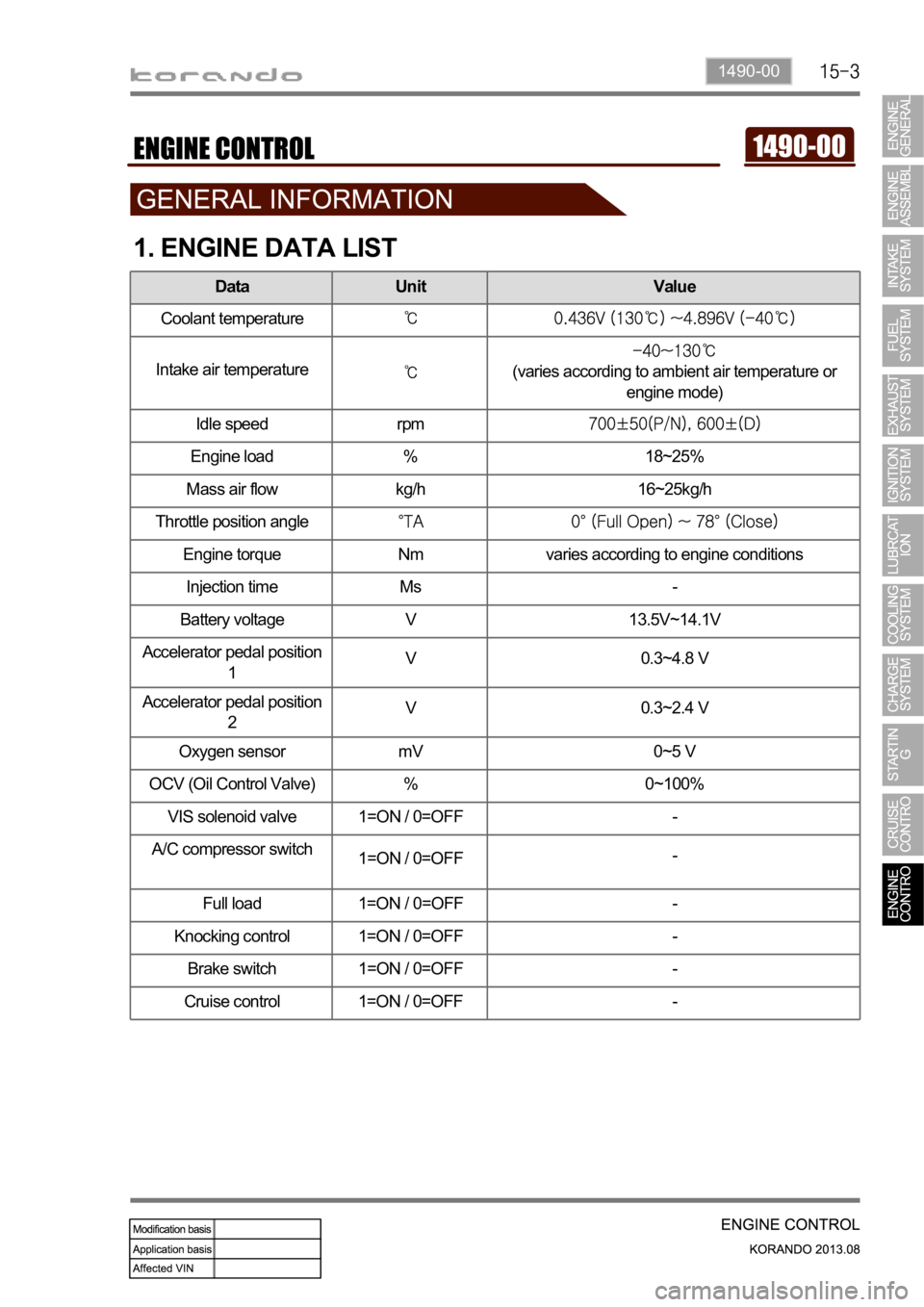
1. ENGINE DATA LIST
Data Unit Value
Coolant temperature
Intake air temperature(varies according to ambient air temperature or
engine mode)
Idle speed rpm
Engine load % 18~25%
Mass air flow kg/h 16~25kg/h
Throttle position angle
Engine torque Nm varies according to engine conditions
Injection time Ms -
Battery voltage V 13.5V~14.1V
Accelerator pedal position
1V 0.3~4.8 V
Accelerator pedal position
2V 0.3~2.4 V
Oxygen sensor mV 0~5 V
OCV (Oil Control Valve) % 0~100%
VIS solenoid valve 1=ON / 0=OFF -
A/C compressor switch
1=ON / 0=OFF-
Full load 1=ON / 0=OFF -
Knocking control 1=ON / 0=OFF -
Brake switch 1=ON / 0=OFF -
Cruise control 1=ON / 0=OFF -
Page 561 of 1336
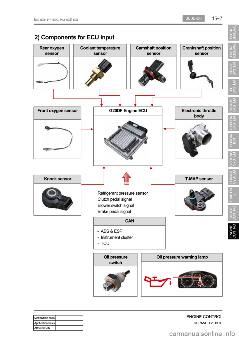
0000-00
Rear oxygen
sensor
2) Components for ECU Input
Coolant temperature
sensorCamshaft position
sensorCrankshaft position
sensor
Front oxygen sensor
Knock sensor
G20DF Engine ECUElectronic throttle
body
Refrigerant pressure sensor
Clutch pedal signal
Blower switch signal
Brake pedal signal
CAN
ABS & ESP
Instrument cluster
TCU -
-
-
Oil pressure
switchOil pressure warning lamp
T-MAP sensor
Page 563 of 1336
1490-00
3. ECU CONTROL
1) Functions
ECU receives and analyzes signals from various sensors and then modifies those signals into
permissible voltage levels and analyzes to control respective actuators.
ECU microprocessor calculates injection period and injection timing proper for engine piston speed and
crankshaft angle based on input data and stored specific map to control the engine power and emission
gas.
Output signal of the ECU microprocessor activates the injector solenoid valve to control the fuel injection
period and injection timing; so controls various actuators in response to engine changes.
Auxiliary function of ECU has adopted to reduce emission gas, improve fuel economy and enhance
safety, comforts and conveniences. For example, there are autocruise and immobilizer and adopted
CAN communication to exchange data among electrical systems (automatic T/M and brake system) in
the vehicle fluently. And the diagnostic tool can be used to diagnose vehicle status and defectives.
water and electromagnetism and there should be no mechanical shocks.
2) Control Functions
Controls by operating stages:
To make optimum combustion under every operating stage, ECU should calculate proper injection
volume in each stage by considering various factors.
Starting injection volume control:
During initial starting, injecting fuel volume will be calculated by function of temperature and engine
cranking speed. Starting injection continues from when the ignition switch is turned to ignition
position to till the engine reaches to allowable minimum speed.
Driving mode control:
If the vehicle runs normally, fuel injection volume will be calculated by accelerator pedal travel and
engine rpm and the drive map will be used to match the drivers inputs with optimum engine power. -
-
-
Page 774 of 1336
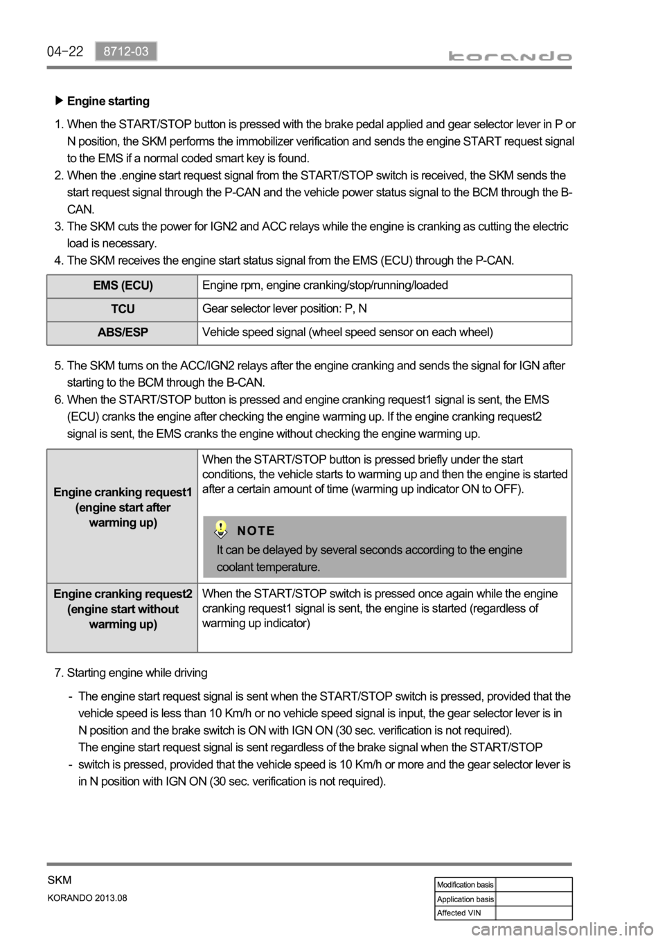
Engine starting
When the START/STOP button is pressed with the brake pedal applied and gear selector lever in P or
N position, the SKM performs the immobilizer verification and sends the engine START request signal
to the EMS if a normal coded smart key is found.
When the .engine start request signal from the START/STOP switch is received, the SKM sends the
start request signal through the P-CAN and the vehicle power status signal to the BCM through the B-
CAN.
The SKM cuts the power for IGN2 and ACC relays while the engine is cranking as cutting the electric
load is necessary.
The SKM receives the engine start status signal from the EMS (ECU) through the P-CAN. 1.
2.
3.
4.
EMS (ECU)Engine rpm, engine cranking/stop/running/loaded
TCUGear selector lever position: P, N
ABS/ESPVehicle speed signal (wheel speed sensor on each wheel)
The SKM turns on the ACC/IGN2 relays after the engine cranking and sends the signal for IGN after
starting to the BCM through the B-CAN.
When the START/STOP button is pressed and engine cranking request1 signal is sent, the EMS
(ECU) cranks the engine after checking the engine warming up. If the engine cranking request2
signal is sent, the EMS cranks the engine without checking the engine warming up. 5.
6.
Engine cranking request1
(engine start after
warming up)When the START/STOP button is pressed briefly under the start
conditions, the vehicle starts to warming up and then the engine is started
after a certain amount of time (warming up indicator ON to OFF).
Engine cranking request2
(engine start without
warming up)When the START/STOP switch is pressed once again while the engine
cranking request1 signal is sent, the engine is started (regardless of
warming up indicator)
It can be delayed by several seconds according to the engine
coolant temperature.
Starting engine while driving 7.
The engine start request signal is sent when the START/STOP switch is pressed, provided that the
vehicle speed is less than 10 Km/h or no vehicle speed signal is input, the gear selector lever is in
N position and the brake switch is ON with IGN ON (30 sec. verification is not required).
The engine start request signal is sent regardless of the brake signal when the START/STOP
switch is pressed, provided that the vehicle speed is 10 Km/h or more and the gear selector lever is
in N position with IGN ON (30 sec. verification is not required). -
-
Page 995 of 1336

0000-00
H. Parking brake
M/T A/T
The parking brake is the mechanical device to
hold the vehicle. When pulling up the lever, the
parking brake cable between the lever and the
rear drum brake trailing shoe pulls the parking
brake lining to contact to drum.
E. Rear brake assembly
The disc brake for 4WD vehicle has the same
structure with the one for 2WD vehicle, but the
appearance and knuckle shape is different from
each other.
Caliper
G. Brake pedal
Disc
F. Parking brake
4WD and 2WD
Front side2WD Rear side
The wheel speed sensor for 4WD has the same
structure and mounting location with the one for
2WD vehicle. But the rear side wheel speed
sensor for 2WD vehicle has different sensor
appearance and mounting status because the
knuckle shape is different from the 4WD vehicle.
Page 1003 of 1336
3680-01
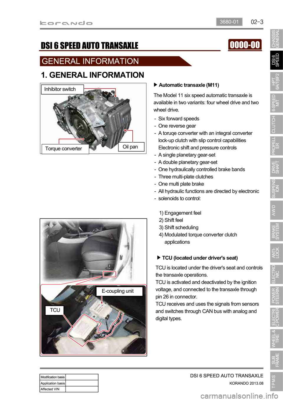
1. GENERAL INFORMATION
Automatic transaxle (M11)
The Model 11 six speed automatic transaxle is
available in two variants: four wheel drive and two
wheel drive.
Six forward speeds
One reverse gear
A toruqe converter with an integral converter
lock-up clutch with slip control capabilities
Electronic shift and pressure controls
A single planetary gear-set
A double planetary gear-set
One hydraulically controlled brake bands
Three multi-plate clutches
One multi plate brake
All hydraulic functions are directed by electronic
solenoids to control: -
-
-
-
-
-
-
-
-
-
Engagement feel
Shift feel
Shift scheduling
Modulated torque converter clutch
applications 1)
2)
3)
4) Inhibitor switch
Oil pan
Torque converter
TCU (located under driver's seat)
TCU is located under the driver's seat and controls
the transaxle operations.
TCU is activated and deactivated by the ignition
voltage, and connected to the transaxle through
pin 26 in connector.
TCU receives and uses the signals from sensors
and switches through CAN bus with analog and
digital types.
E-coupling unit
TCU
Page 1014 of 1336
5. TRANSAXLE ELECTRONIC CONTROL SYSTEM
1) General Information
The transmission control unit (TCU) and its input/output network control the following transmission
operations:
Shift timing
Line pressure
Clutch pressure (shift feel)
Torque converter clutch -
-
-
-
also uses these signals when determining transaxle operating strategy. Using all of these input signals,
the TCU can determine when the time and conditions are right for a shift, or when to apply or release the
torque converter clutch. It will also determine the pressure needed to optimise shift feel. To accomplish
this, the TCU operates six variable bleed control solenoids and four on/off solenoids to control transaxle
operation.
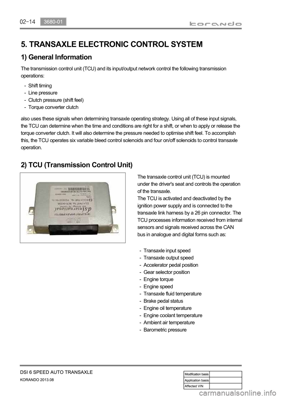
2) TCU (Transmission Control Unit)
The transaxle control unit (TCU) is mounted
under the driver's seat and controls the operation
of the transaxle.
The TCU is activated and deactivated by the
ignition power supply and is connected to the
transaxle link harness by a 26 pin connector. The
TCU processes information received from internal
sensors and signals received across the CAN
bus in analogue and digital forms such as:
Transaxle input speed
Transaxle output speed
Accelerator pedal position
Gear selector position
Engine torque
Engine speed
Transaxle fluid temperature
Brake pedal status
Engine oil temperature
Engine coolant temperature
Ambient air temperature
Barometric pressure -
-
-
-
-
-
-
-
-
-
-
-