SSANGYONG KORANDO 2013 Service Manual
KORANDO 2013
SSANGYONG
SSANGYONG
https://www.carmanualsonline.info/img/67/57503/w960_57503-0.png
SSANGYONG KORANDO 2013 Service Manual
Page 185 of 1336
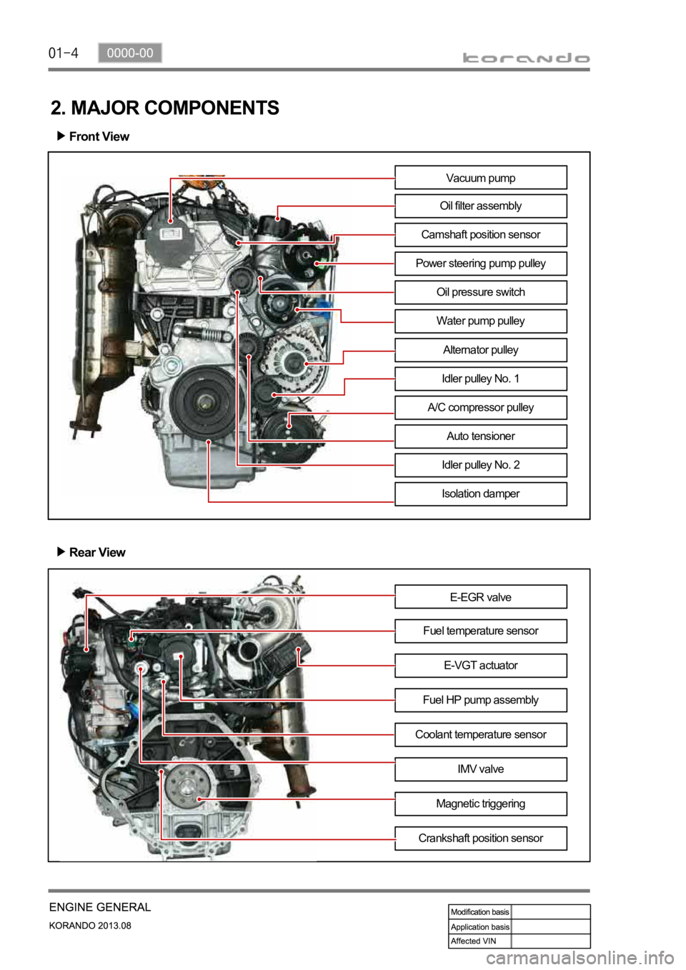
2. MAJOR COMPONENTS
Front View
Rear View
E-EGR valve
Fuel temperature sensor
Fuel HP pump assemblyE-VGT actuator
Coolant temperature sensor
IMV valve
Magnetic triggering
Crankshaft position sensor
Vacuum pump
Oil filter assembly
Camshaft position sensor
Power steering pump pulley
Water pump pulley
Alternator pulley
Idler pulley No. 1
A/C compressor pulley
Auto tensioner
Idler pulley No. 2
Isolation damper
Oil pressure switch
Page 197 of 1336
0000-00
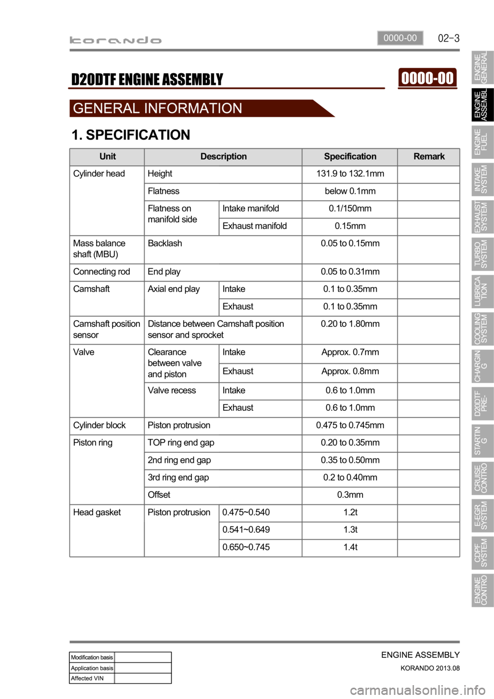
1. SPECIFICATION
Unit Description Specification Remark
Cylinder head Height 131.9 to 132.1mm
Flatness below 0.1mm
Flatness on
manifold sideIntake manifold 0.1/150mm
Exhaust manifold 0.15mm
Mass balance
shaft (MBU)Backlash 0.05 to 0.15mm
Connecting rod End play 0.05 to 0.31mm
Camshaft Axial end play Intake 0.1 to 0.35mm
Exhaust 0.1 to 0.35mm
Camshaft position
sensorDistance between Camshaft position
sensor and sprocket0.20 to 1.80mm
Valve Clearance
between valve
and pistonIntake Approx. 0.7mm
Exhaust Approx. 0.8mm
Valve recess Intake 0.6 to 1.0mm
Exhaust 0.6 to 1.0mm
Cylinder block Piston protrusion 0.475 to 0.745mm
Piston ring TOP ring end gap 0.20 to 0.35mm
2nd ring end gap 0.35 to 0.50mm
3rd ring end gap 0.2 to 0.40mm
Offset 0.3mm
Head gasket Piston protrusion 0.475~0.540 1.2t
0.541~0.649 1.3t
0.650~0.745 1.4t
Page 217 of 1336
0000-00
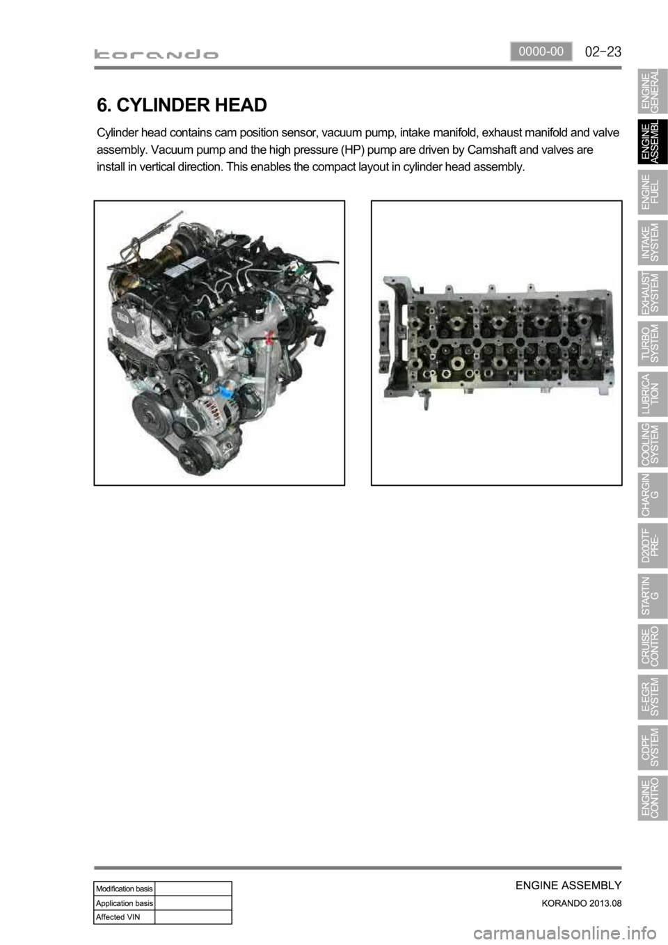
6. CYLINDER HEAD
Cylinder head contains cam position sensor, vacuum pump, intake manifold, exhaust manifold and valve
assembly. Vacuum pump and the high pressure (HP) pump are driven by Camshaft and valves are
install in vertical direction. This enables the compact layout in cylinder head assembly.
Page 218 of 1336
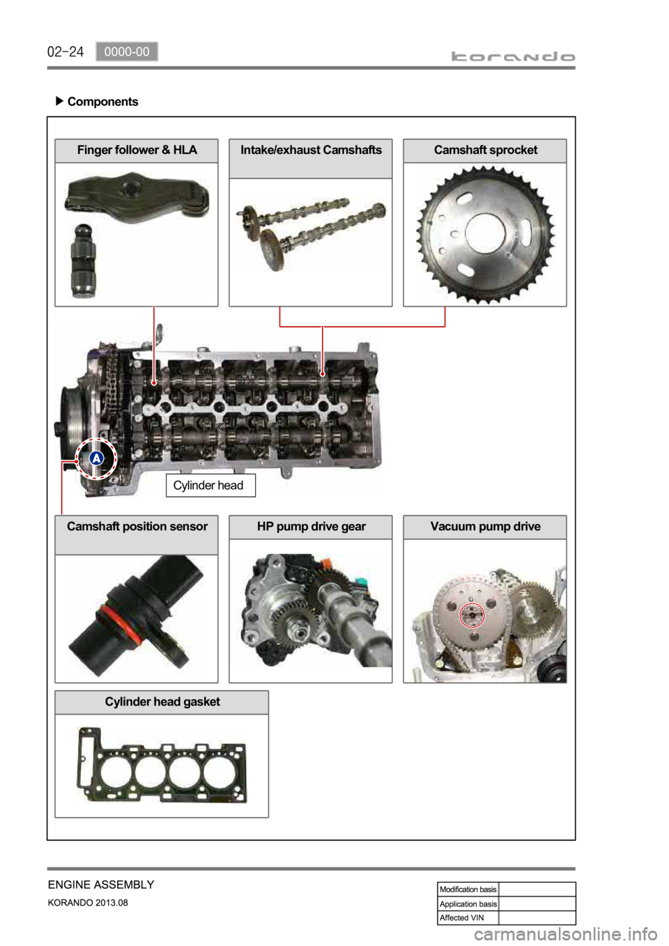
Vacuum pump drive
Intake/exhaust CamshaftsCamshaft sprocketFinger follower & HLA
Components
Cylinder head
Camshaft position sensorHP pump drive gear
Cylinder head gasket
Page 250 of 1336
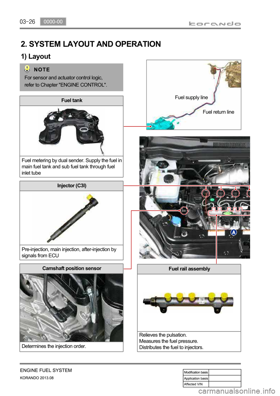
Fuel rail assembly
Relieves the pulsation.
Measures the fuel pressure.
Distributes the fuel to injectors.Camshaft position sensor
Determines the injection order.
Injector (C3I)
Pre-injection, main injection, after-injection by
signals from ECU
Fuel tank
Fuel metering by dual sender. Supply the fuel in
main fuel tank and sub fuel tank through fuel
inlet tube
2. SYSTEM LAYOUT AND OPERATION
1) Layout
Fuel supply line
Fuel return line
For sensor and actuator control logic,
refer to Chapter "ENGINE CONTROL".
Page 254 of 1336
The engine ECU calculates the accelerator pedal based on the input signals from various sensors, and
controls the overall operation of the vehicle.
The ECU receives the signals from various sensor through data line, and performs effective air-fuel ratio
control based on these signals.
The crankshaft speed (position) sensor measures the engine speed, and the camshaft speed (position)
sensor determines the order of injections, and the ECU detects the amount of the accelerator pedal
depressed (driver's will) by receiving the electrical signals from the accelerator pedal sensor.
The mass air flow sensor detects the volume of intake air and sends the value to the ECU.
The major function of the ECU is controlling air-fuel ratio to reduce the emission level (EGR valve control)
by detecting instantaneous air flow change with the signals from the mass air flow sensor.
Also, the ECU uses the signals from the coolant temperature & air temperature sensors, booster pressure
sensor, atmospheric pressure sensor to: a) determine injection starting point and set value for pilot
injection, and b) deal with various operations and variable conditions.
Page 375 of 1336
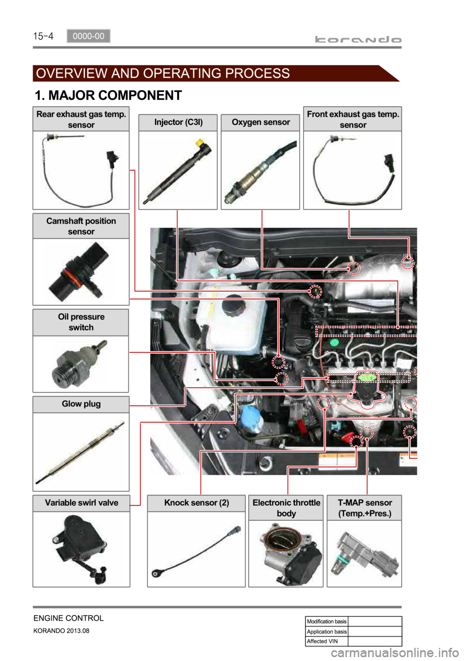
Variable swirl valveElectronic throttle
bodyT-MAP sensor
(Temp.+Pres.)
Injector (C3I)Oxygen sensorFront exhaust gas temp.
sensor
Glow plug
Knock sensor (2)
Oil pressure
switch
1. MAJOR COMPONENT
Rear exhaust gas temp.
sensor
Camshaft position
sensor
Page 423 of 1336
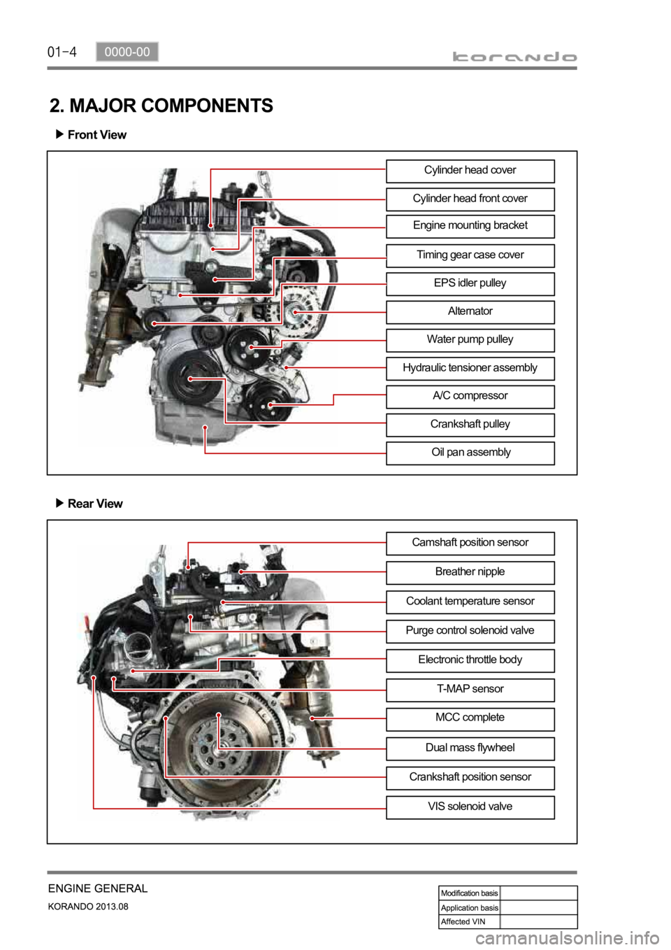
Engine mounting bracket
2. MAJOR COMPONENTS
Front View
Cylinder head front cover
Timing gear case cover
EPS idler pulley
Alternator
Water pump pulley
A/C compressor
Crankshaft pulley
Oil pan assembly
Rear View
Camshaft position sensor
Breather nipple
Purge control solenoid valveCoolant temperature sensor
Electronic throttle body
T-MAP sensor
MCC complete
VIS solenoid valve Cylinder head cover
Dual mass flywheel
Crankshaft position sensor
Hydraulic tensioner assembly
Page 449 of 1336
Components
Exhaust camshaftOCVFinger follower & HLA
Intake camshaftIntake camshaft CVVT
gearCamshaft position
sensor
Page 500 of 1336
1443-01
1. OVERVIEW
The ignition system is to supply high voltage generated from the ignition coil to the spark plug. The
G20DF engine is equipped with the independent type direct ignition system that the ignition coil is
installed in each cylinder.
The basic ignition timing in each cylinder is determined by the signals from camshaft position sensor and
crankshaft position sensor.
This ignition system controls the electronic ignition timing received from the engine ECU. To control the
ignition timing precisely, the ECU use the information below:
Engine load
Coolant temperature
Intake air temperature
Engine rpm
Camshaft position sensor (CPS)
Crankshaft position sensor (CKS) -
-
-
-
-
-
If the signal from the camshaft position sensor is not delivered to the engine ECU, the ignition coil and
fuel system cannot be operated.
