cooling SSANGYONG KORANDO 2013 Service Manual
[x] Cancel search | Manufacturer: SSANGYONG, Model Year: 2013, Model line: KORANDO, Model: SSANGYONG KORANDO 2013Pages: 1336, PDF Size: 92.18 MB
Page 207 of 1336
0000-00
4. CHECK AND INSPECTION
1) Cylinder
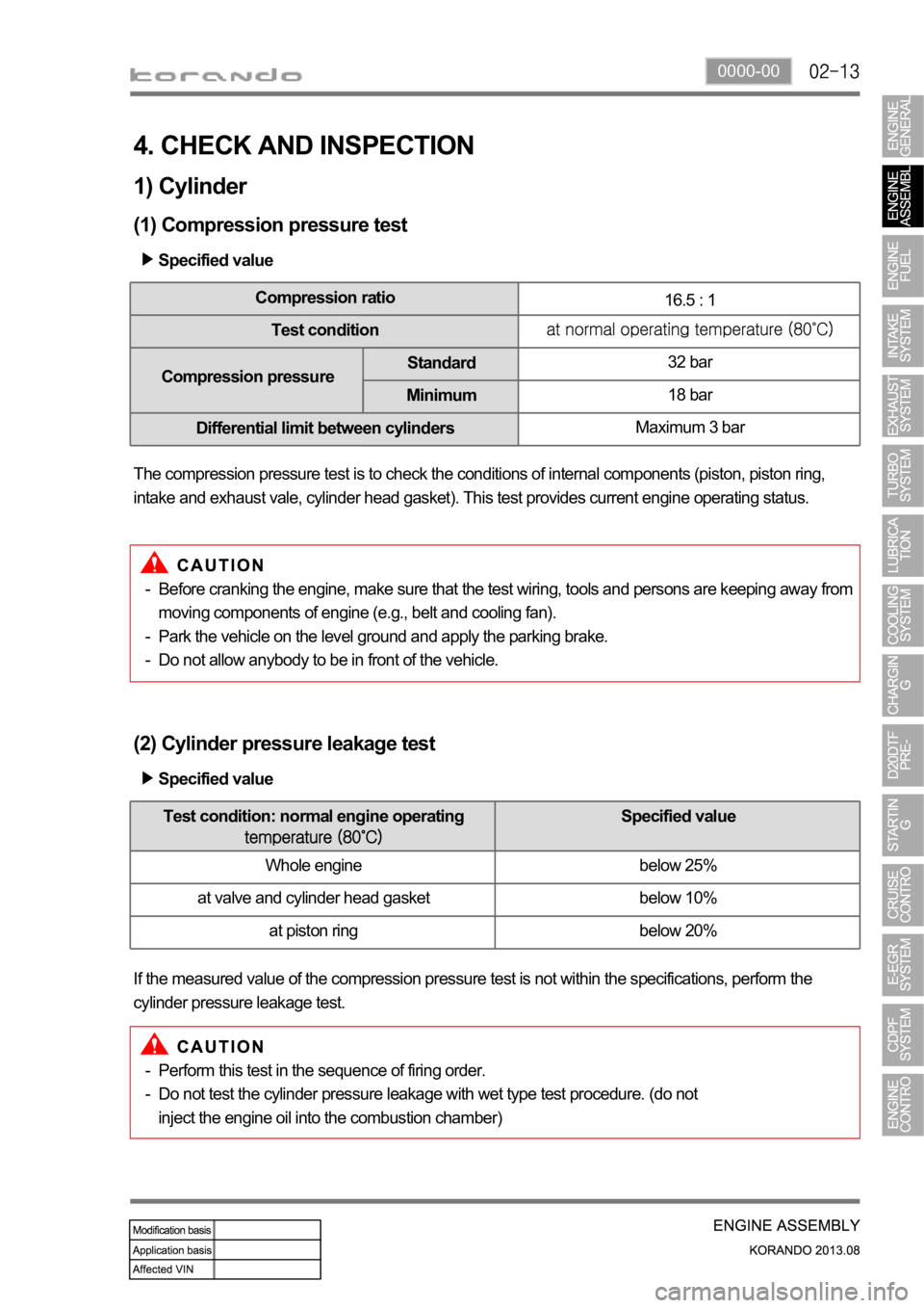
(1) Compression pressure test
Specified value
Compression ratio
16.5 : 1
Test condition
Compression pressureStandard32 bar
Minimum18 bar
Differential limit between cylindersMaximum 3 bar
The compression pressure test is to check the conditions of internal components (piston, piston ring,
intake and exhaust vale, cylinder head gasket). This test provides current engine operating status.
Before cranking the engine, make sure that the test wiring, tools and persons are keeping away from
moving components of engine (e.g., belt and cooling fan).
Park the vehicle on the level ground and apply the parking brake.
Do not allow anybody to be in front of the vehicle. -
-
-
(2) Cylinder pressure leakage test
If the measured value of the compression pressure test is not within the specifications, perform the
cylinder pressure leakage test.Specified value
Perform this test in the sequence of firing order.
Do not test the cylinder pressure leakage with wet type test procedure. (do not
inject the engine oil into the combustion chamber) -
-
Test condition: normal engine operating Specified value
Whole engine below 25%
at valve and cylinder head gasket below 10%
at piston ring below 20%
Page 295 of 1336
0000-00
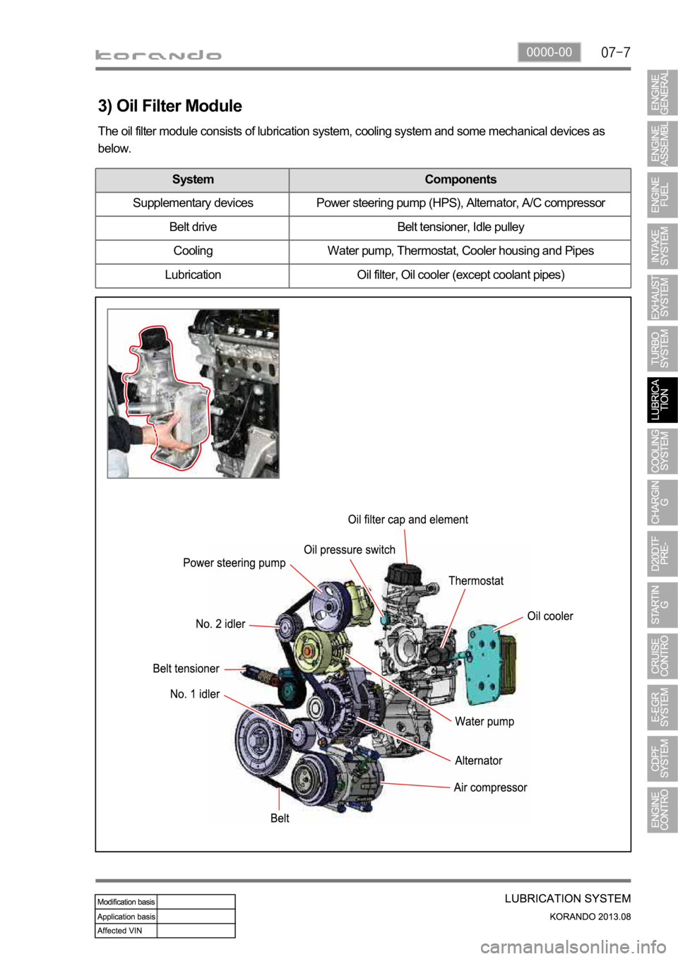
3) Oil Filter Module
The oil filter module consists of lubrication system, cooling system and some mechanical devices as
below.
System Components
Supplementary devices Power steering pump (HPS), Alternator, A/C compressor
Belt drive Belt tensioner, Idle pulley
Cooling Water pump, Thermostat, Cooler housing and Pipes
Lubrication Oil filter, Oil cooler (except coolant pipes)
Page 297 of 1336
0000-00
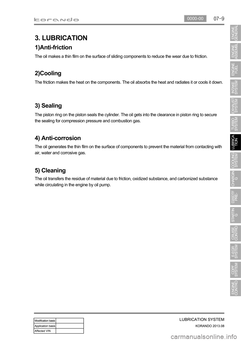
3. LUBRICATION
1)Anti-friction
The oil makes a thin film on the surface of sliding components to reduce the wear due to friction.
2)Cooling
The friction makes the heat on the components. The oil absorbs the heat and radiates it or cools it down.
3) Sealing
The piston ring on the piston seals the cylinder. The oil gets into the clearance in piston ring to secure
the sealing for compression pressure and combustion gas.
4) Anti-corrosion
The oil generates the thin film on the surface of components to prevent the material from contacting with
air, water and corrosive gas.
5) Cleaning
The oil transfers the residue of material due to friction, oxidized substance, and carbonized substance
while circulating in the engine by oil pump.
Page 298 of 1336
0000-00
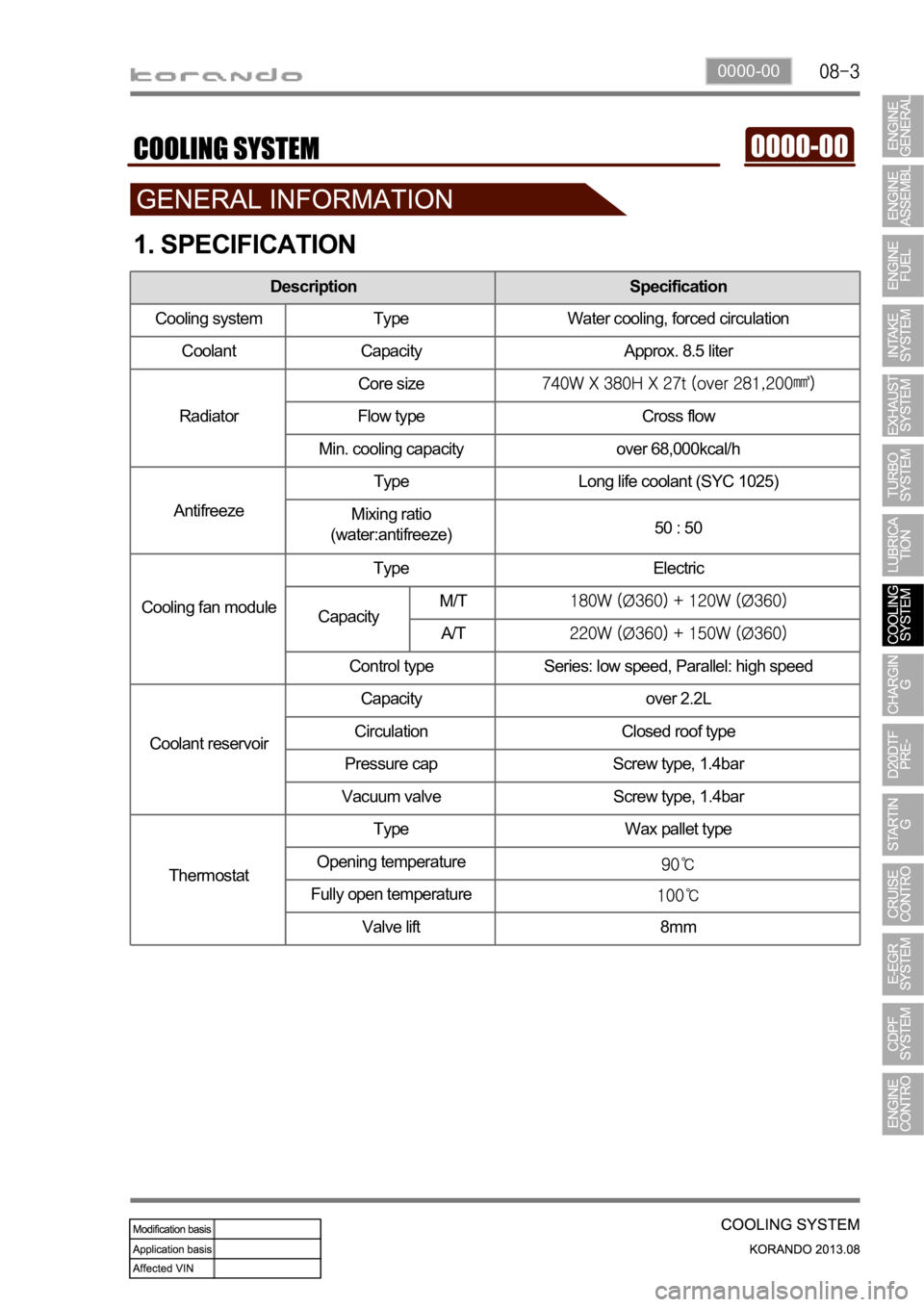
1. SPECIFICATION
Description Specification
Cooling system Type Water cooling, forced circulation
Coolant Capacity Approx. 8.5 liter
RadiatorCore size
Flow type Cross flow
Min. cooling capacity over 68,000kcal/h
AntifreezeType Long life coolant (SYC 1025)
Mixing ratio
(water:antifreeze)50 : 50
Cooling fan moduleType Electric
Control type Series: low speed, Parallel: high speed
Coolant reservoirCapacity over 2.2L
Circulation Closed roof type
Pressure cap Screw type, 1.4bar
Vacuum valve Screw type, 1.4bar
ThermostatType Wax pallet type
Opening temperature
Fully open temperature
Valve lift 8mm
CapacityM/T
A/T
Page 299 of 1336
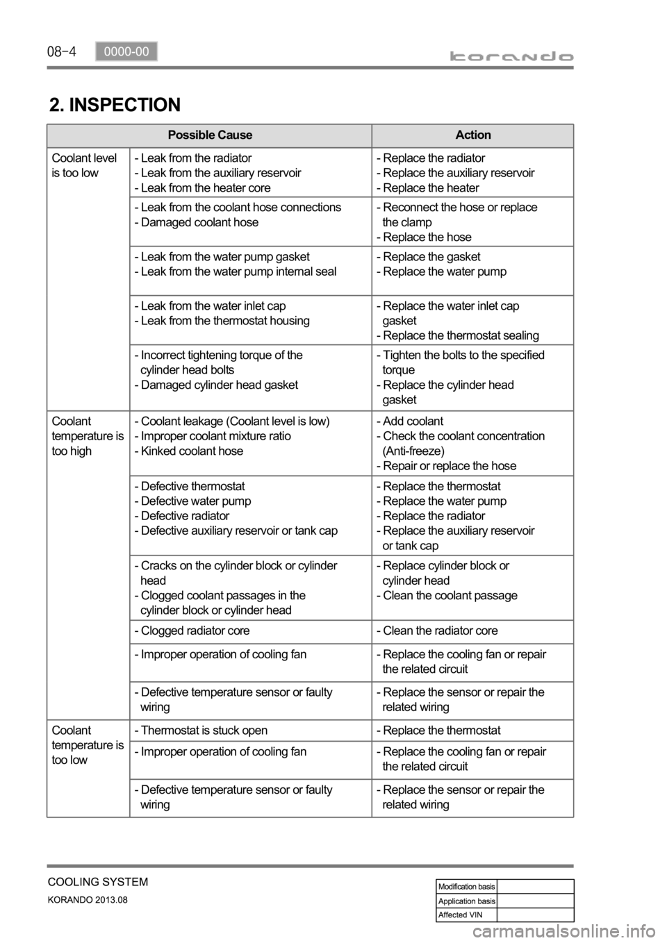
2. INSPECTION
Possible Cause Action
Coolant level
is too low- Leak from the radiator
- Leak from the auxiliary reservoir
- Leak from the heater core- Replace the radiator
- Replace the auxiliary reservoir
- Replace the heater
- Leak from the coolant hose connections
- Damaged coolant hose- Reconnect the hose or replace
the clamp
- Replace the hose
- Leak from the water pump gasket
- Leak from the water pump internal seal- Replace the gasket
- Replace the water pump
- Leak from the water inlet cap
- Leak from the thermostat housing- Replace the water inlet cap
gasket
- Replace the thermostat sealing
- Incorrect tightening torque of the
cylinder head bolts
- Damaged cylinder head gasket- Tighten the bolts to the specified
torque
- Replace the cylinder head
gasket
Coolant
temperature is
too high- Coolant leakage (Coolant level is low)
- Improper coolant mixture ratio
- Kinked coolant hose- Add coolant
- Check the coolant concentration
(Anti-freeze)
- Repair or replace the hose
- Defective thermostat
- Defective water pump
- Defective radiator
- Defective auxiliary reservoir or tank cap- Replace the thermostat
- Replace the water pump
- Replace the radiator
- Replace the auxiliary reservoir
or tank cap
- Cracks on the cylinder block or cylinder
head
- Clogged coolant passages in the
cylinder block or cylinder head- Replace cylinder block or
cylinder head
- Clean the coolant passage
- Clogged radiator core - Clean the radiator core
- Improper operation of cooling fan - Replace the cooling fan or repair
the related circuit
- Defective temperature sensor or faulty
wiring- Replace the sensor or repair the
related wiring
Coolant
temperature is
too low- Thermostat is stuck open - Replace the thermostat
- Improper operation of cooling fan - Replace the cooling fan or repair
the related circuit
- Defective temperature sensor or faulty
wiring- Replace the sensor or repair the
related wiring
Page 302 of 1336
0000-00
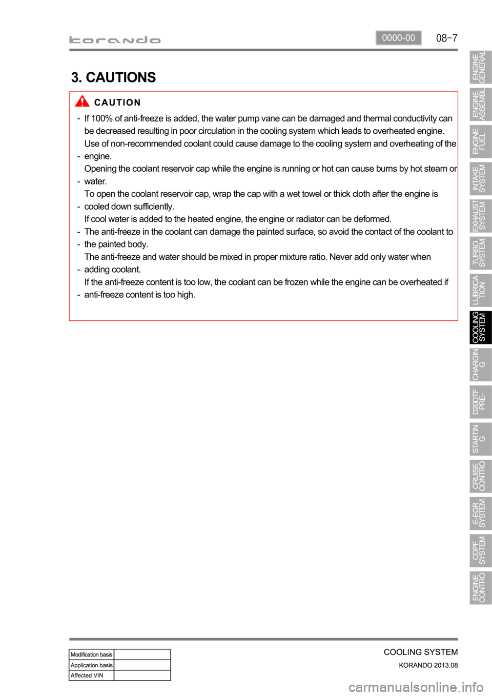
3. CAUTIONS
If 100% of anti-freeze is added, the water pump vane can be damaged and thermal conductivity can
be decreased resulting in poor circulation in the cooling system which leads to overheated engine.
Use of non-recommended coolant could cause damage to the cooling system and overheating of the
engine.
Opening the coolant reservoir cap while the engine is running or hot can cause burns by hot steam o
r
water.
To open the coolant reservoir cap, wrap the cap with a wet towel or thick cloth after the engine is
cooled down sufficiently.
If cool water is added to the heated engine, the engine or radiator can be deformed.
The anti-freeze in the coolant can damage the painted surface, so avoid the contact of the coolant to
the painted body.
The anti-freeze and water should be mixed in proper mixture ratio. Never add only water when
adding coolant.
If the anti-freeze content is too low, the coolant can be frozen while the engine can be overheated if
anti-freeze content is too high. -
-
-
-
-
-
-
-
Page 354 of 1336

1793-01
E-EGR bypass valve Solenoid valve Drivien byVacuum
(Solenoid valve)
1. SPECIFICATION
Item
E-EGR valve Motor EGR response time 50 mS
Driven by DC motor
Valve EGR gas flow rate 120 Kg/h
Position sensor Sensing type Hall sensor
Supply voltage
Signal range 5% ~ 95%
Max. current consumption
E-EGR cooler Cooling capacity 8.3 kW or more
Coolin fin type Wavy fin
Coller type U-shaped
Page 379 of 1336
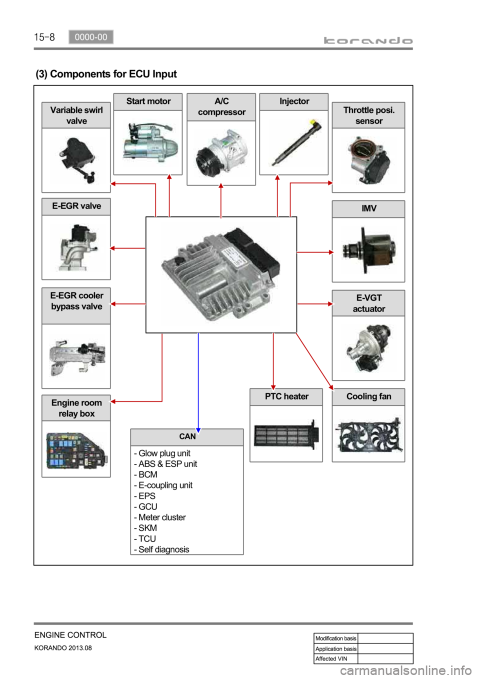
Engine room
relay box
E-EGR valve
Cooling fan
E-EGR cooler
bypass valveE-VGT
actuator
IMV
Throttle posi.
sensor
InjectorA/C
compressorStart motor
Variable swirl
valve
(3) Components for ECU Input
PTC heater
CAN
- Glow plug unit
- ABS & ESP unit
- BCM
- E-coupling unit
- EPS
- GCU
- Meter cluster
- SKM
- TCU
- Self diagnosis
Page 405 of 1336
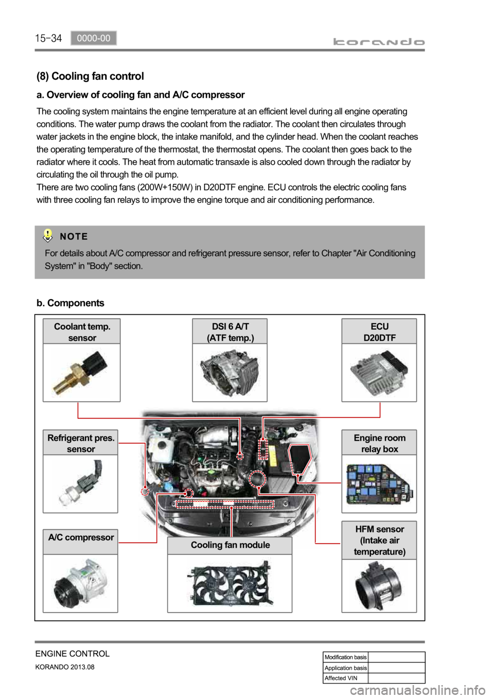
Coolant temp.
sensor
Refrigerant pres.
sensor
A/C compressor
ECU
D20DTFDSI 6 A/T
(ATF temp.)
Cooling fan module
HFM sensor
(Intake air
temperature)
Engine room
relay box
(8) Cooling fan control
a. Overview of cooling fan and A/C compressor
The cooling system maintains the engine temperature at an efficient level during all engine operating
conditions. The water pump draws the coolant from the radiator. The coolant then circulates through
water jackets in the engine block, the intake manifold, and the cylinder head. When the coolant reaches
the operating temperature of the thermostat, the thermostat opens. The coolant then goes back to the
radiator where it cools. The heat from automatic transaxle is also cooled down through the radiator by
circulating the oil through the oil pump.
There are two cooling fans (200W+150W) in D20DTF engine. ECU controls the electric cooling fans
with three cooling fan relays to improve the engine torque and air conditioning performance.
For details about A/C compressor and refrigerant pressure sensor, refer to Chapter "Air Conditioning
System" in "Body" section.
b. Components
Page 406 of 1336

0000-00
c. Input/Output for cooling fan and A/C compressor