lights SSANGYONG KORANDO 2013 Service Manual
[x] Cancel search | Manufacturer: SSANGYONG, Model Year: 2013, Model line: KORANDO, Model: SSANGYONG KORANDO 2013Pages: 1336, PDF Size: 92.18 MB
Page 245 of 1336
0000-00
4. CAUTIONS FOR DI ENGINE
1) Cautions for DI Engine
This chapter describes the cautions for DI engine equipped vehicle. This includes the water separation
from engine, warning lights, symptoms when engine malfunctioning, causes and actions.
DI Engine 1.
Comparatively conventional diesel engines, DI engine controls the fuel injection and timing electrically,
delivers high power and reduces less emission.
System Safety Mode 2.
When a severe failure has been occurred in a vehicle, the system safety mode is activated to protect the
system. It reduces the driving force, restricts the engine speed (rpm) and stops engine operation. Refer
to "Diagnosis" section in this manual.
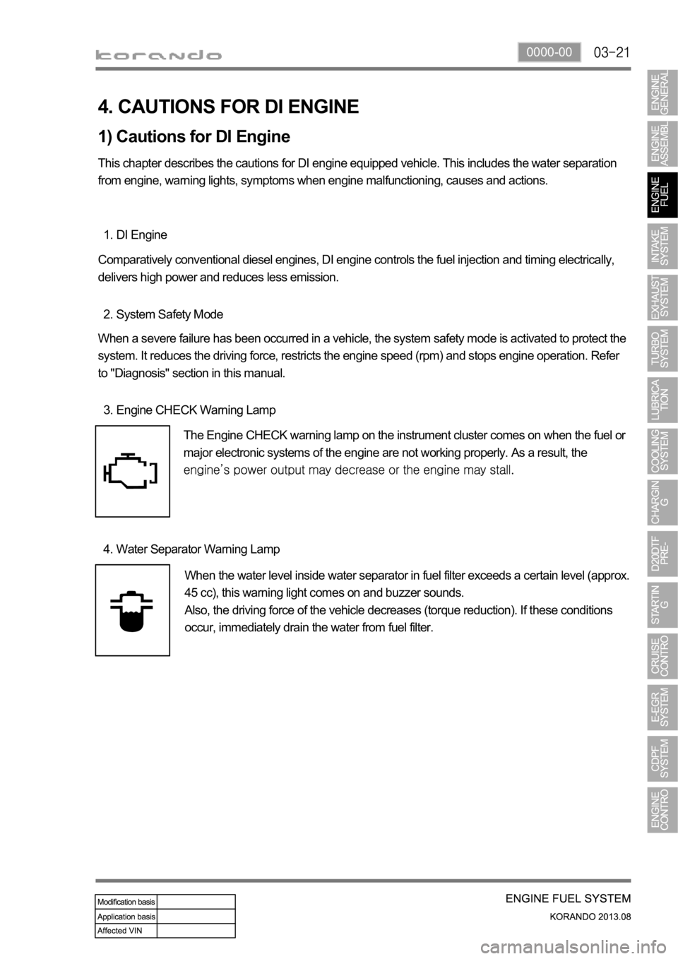
Engine CHECK Warning Lamp 3.
The Engine CHECK warning lamp on the instrument cluster comes on when the fuel or
major electronic systems of the engine are not working properly. As a result, the
Water Separator Warning Lamp 4.
When the water level inside water separator in fuel filter exceeds a certain level (approx.
45 cc), this warning light comes on and buzzer sounds.
Also, the driving force of the vehicle decreases (torque reduction). If these conditions
occur, immediately drain the water from fuel filter.
Page 344 of 1336
2) Traffic Conditions for Using Cruise Control
Use the cruise control system only when the traffic is not jammed, driving on motorways or highways
where there is no sudden change in the driving condition due to traffic lights, pedestrian, etc.
Improper use of the cruise control could be dangerous.
Do not use on winding roadsyy .
Do not use in heavy traffic.
Do not use on slippery, wet roads.
This could result in a loss of control, collision, and/or personal injuries. -
-
-
Page 547 of 1336
2) Traffic Conditions for Using Cruise Control
Use the cruise control system only when the traffic is not jammed, driving on motorways or highways
where there is no sudden change in the driving condition due to traffic lights, pedestrian, etc.
Improper use of the cruise control could be dangerous.
Do not use on winding roads.yy
Do not use in heavy traffic.yy
Do not use on slippery, wet roads. -
-
-
This could result in a loss of control, collision, and/or personal injuries.
The described speed value may vary slightly depending on the road conditions.
Page 807 of 1336
8010-01
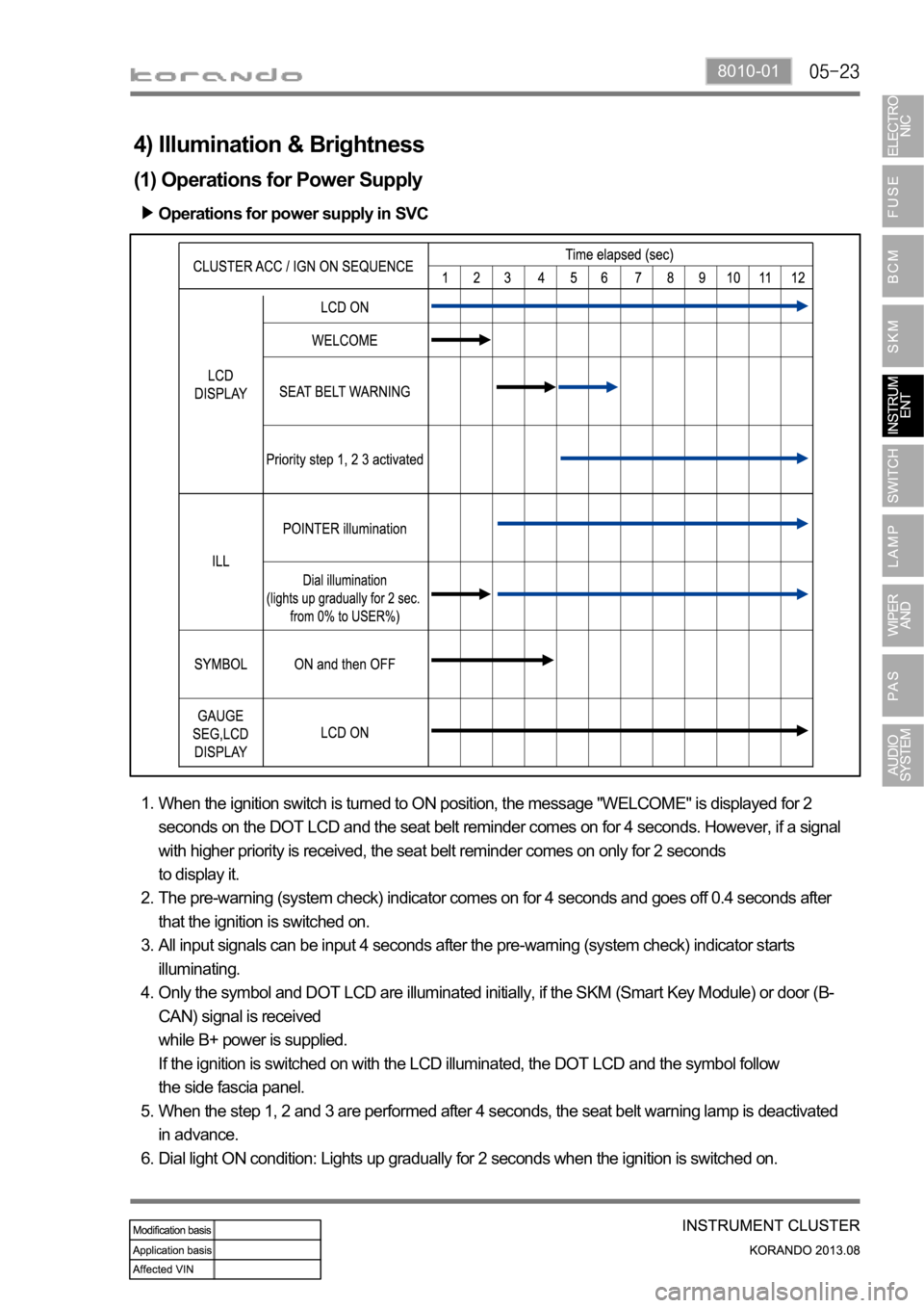
Operations for power supply in SVC
When the ignition switch is turned to ON position, the message "WELCOME" is displayed for 2
seconds on the DOT LCD and the seat belt reminder comes on for 4 seconds. However, if a signal
with higher priority is received, the seat belt reminder comes on only for 2 seconds
to display it.
The pre-warning (system check) indicator comes on for 4 seconds and goes off 0.4 seconds after
that the ignition is switched on.
All input signals can be input 4 seconds after the pre-warning (system check) indicator starts
illuminating.
Only the symbol and DOT LCD are illuminated initially, if the SKM (Smart Key Module) or door (B-
CAN) signal is received
while B+ power is supplied.
If the ignition is switched on with the LCD illuminated, the DOT LCD and the symbol follow
the side fascia panel.
When the step 1, 2 and 3 are performed after 4 seconds, the seat belt warning lamp is deactivated
in advance.
Dial light ON condition: Lights up gradually for 2 seconds when the ignition is switched on. 1.
2.
3.
4.
5.
6.
4) Illumination & Brightness
(1) Operations for Power Supply
Page 873 of 1336
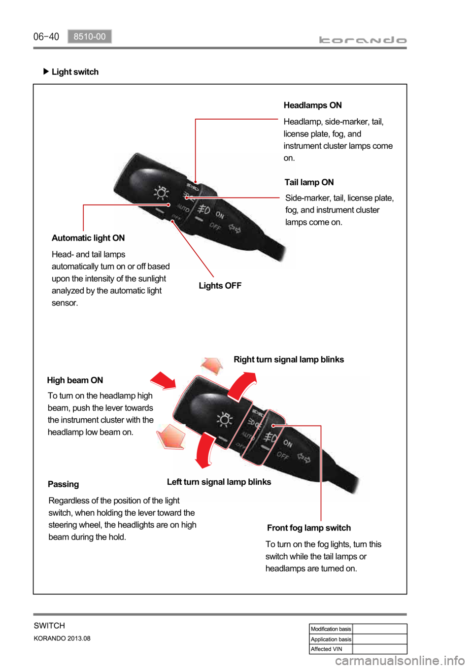
Light switch
Headlamps ON
Headlamp, side-marker, tail,
license plate, fog, and
instrument cluster lamps come
on.
Tail lamp ON
Side-marker, tail, license plate,
fog, and instrument cluster
lamps come on.
Automatic light ON
Head- and tail lamps
automatically turn on or off based
upon the intensity of the sunlight
analyzed by the automatic light
sensor.Lights OFF
High beam ON
To turn on the headlamp high
beam, push the lever towards
the instrument cluster with the
headlamp low beam on.Right turn signal lamp blinks
Passing
Regardless of the position of the light
switch, when holding the lever toward the
steering wheel, the headlights are on high
beam during the hold.Front fog lamp switch
To turn on the fog lights, turn this
switch while the tail lamps or
headlamps are turned on. Left turn signal lamp blinks
Page 911 of 1336
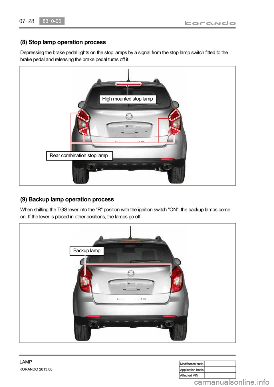
(8) Stop lamp operation process
Depressing the brake pedal lights on the stop lamps by a signal from the stop lamp switch fitted to the
brake pedal and releasing the brake pedal turns off it.
(9) Backup lamp operation process
When shifting the TGS lever into the "R" position with the ignition switch "ON", the backup lamps come
on. If the lever is placed in other positions, the lamps go off.
High mounted stop lamp
Rear combination stop lamp
Backup lamp
Page 1015 of 1336
3680-01
This information is used by the TCU to decide which shift pattern to select and for shift energy
management. Electro-hydraulic solenoid valves and variable bleed solenoids control the transaxle gear
changes.
Six variable bleed solenoids and four on/off solenoids are used to direct transaxle fluid flow to control the
fluid pressure within the three clutches and two bands. Separate pressure regulators are used
exclusively for torque converter clutch control and main transaxle line pressure.
The TCU monitors all TCU inputs and outputs to confirm correct system operation. If a fault occurs the
TCU is able to perform default action and inform the driver of the problem through the instrument cluster
warning lights. Detailed information is available via trouble codes which can be read with the service tool.
Page 1043 of 1336
3660-01
5. TRANSAXLE ELECTRONIC CONTROL SYSTEM
1) General Information
The transmission control unit (TCU) and its input/output network control the following transmission
operations:
Shift timing
Line pressure
Clutch pressure (shift feel)
Torque converter clutch -
-
-
-
also uses these signals when determining transaxle operating strategy. Using all of these input signals,
the TCU can determine when the time and conditions are right for a shift, or when to apply or release the
torque converter clutch. It will also determine the pressure needed to optimise shift feel.
2) TCU (Transmission Control Unit)
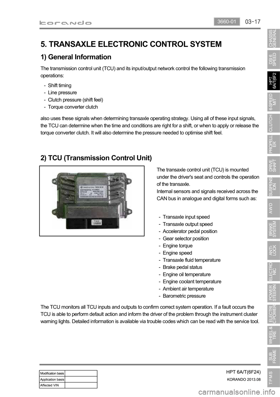
The transaxle control unit (TCU) is mounted
under the driver's seat and controls the operation
of the transaxle.
Internal sensors and signals received across the
CAN bus in analogue and digital forms such as:
Transaxle input speed
Transaxle output speed
Accelerator pedal position
Gear selector position
Engine torque
Engine speed
Transaxle fluid temperature
Brake pedal status
Engine oil temperature
Engine coolant temperature
Ambient air temperature
Barometric pressure -
-
-
-
-
-
-
-
-
-
-
-
The TCU monitors all TCU inputs and outputs to confirm correct system operation. If a fault occurs the
TCU is able to perform default action and inform the driver of the problem through the instrument cluster
warning lights. Detailed information is available via trouble codes which can be read with the service tool.