4WD SSANGYONG MUSSO 2003 Owner's Manual
[x] Cancel search | Manufacturer: SSANGYONG, Model Year: 2003, Model line: MUSSO, Model: SSANGYONG MUSSO 2003Pages: 1574, PDF Size: 26.41 MB
Page 1059 of 1574
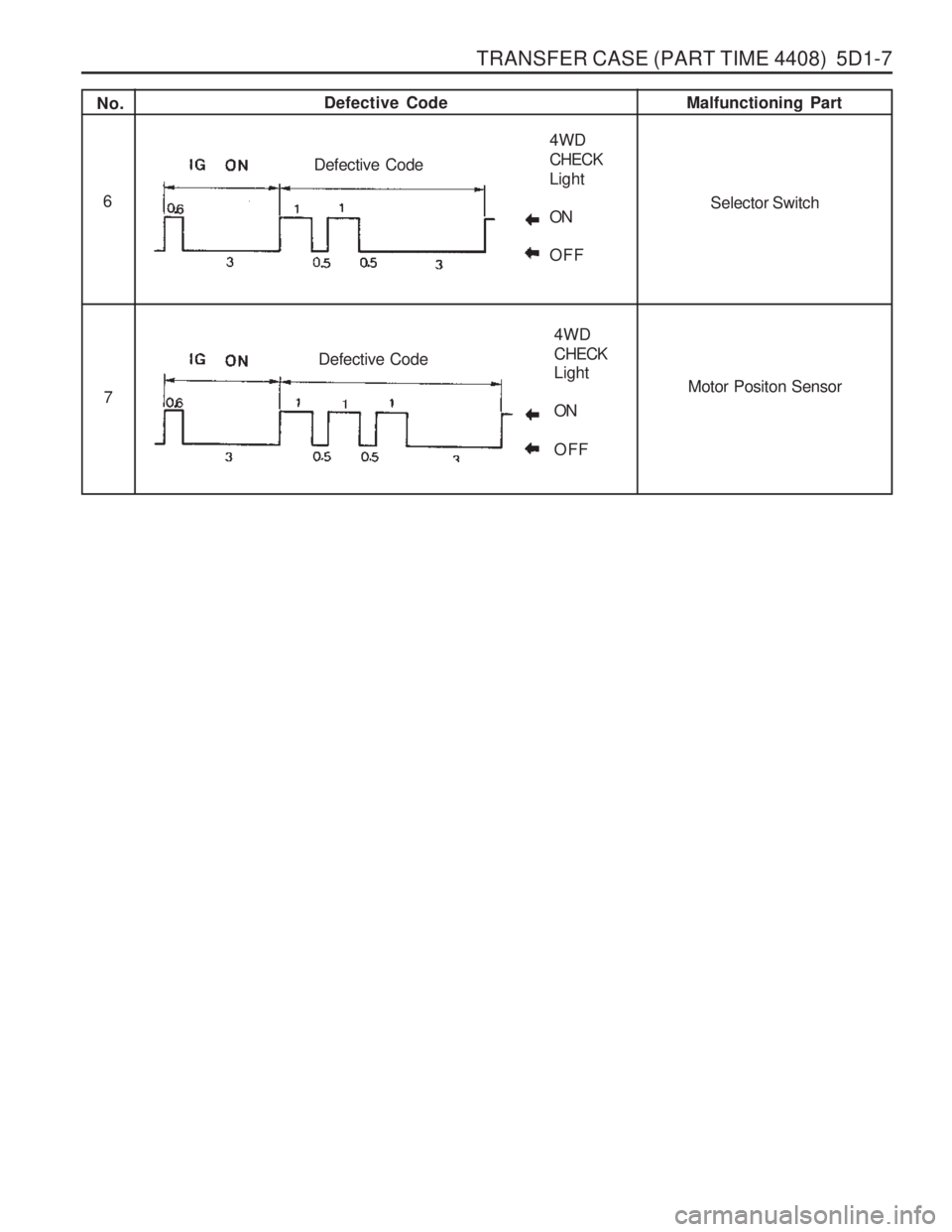
TRANSFER CASE (PART TIME 4408) 5D1-7
No.Defective Code
Malfunctioning Part
6
7
Selector Switch
Motor Positon Sensor
4WD CHECKLight ONOFF
Defective Code
4WD CHECK Light ON OFF
Defective Code
Page 1070 of 1574
5D1-18 TRANSFER CASE (PART TIME 4408)
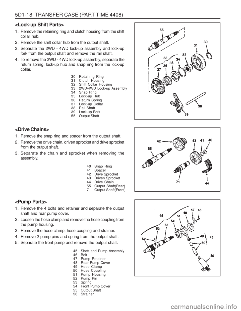
1. Remove the retaining ring and clutch housing from the shiftcollar hub.
2. Remove the shift collar hub from the output shaft.
3. Separate the 2WD - 4WD lock-up assembly and lock-up fork from the output shaft and remove the rail shaft.
4. To remove the 2WD - 4WD lock-up assembly, separate the return spring, lock-up hub and snap ring from the lock-up
collar.
30 Retaining Ring
31 Clutch Housing
32 Shift Collar Housing
33 2WD/4WD Lock-up Assembly
34 Snap Ring
35 Lock-up Hub
36 Return Spring
37 Lock-up Collar
38 Rail Shaft
39 Lock-up Fork
55 Output Shaft
40 Snap Ring
41 Spacer
42 Drive Sprocket
43 Driven Sprocket
44 Drive Chain
55 Output Shaft(Rear)
71 Output Shaft(Front)
1. Remove the snap ring and spacer from the output shaft.
2. Remove the drive chain, driven sprocket and drive sprocket
from the output shaft.
3. Separate the chain and sprocket when removing the assembly.
1. Remove the 4 bolts and retainer and separate the output
shaft and rear pump cover.
2. Loosen the hose clamp and remove the hose coupling from the pump housing.
3. Remove the hose clamp, hose coupling and strainer.
4. Remove 2 pump pins and spring from the output shaft.
5. Separate the front pump and remove the output shaft.
45 Shaft and Pump Assembly
46 Bolt
47 Pump Retainer
48 Rear Pump Cover
49 Hose Clamp
50 Hose Coupling
51 Pump Housing
52 Pump Pin
53 Spring
54 Front Pump Cover
55 Output Shaft
56 Strainer
Page 1083 of 1574
TRANSFER CASE (PART TIME 4408) 5D1-31
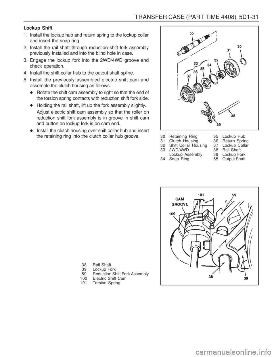
Lockup Shift
1. Install the lockup hub and return spring to the lockup collarand insert the snap ring.
2. Install the rail shaft through reduction shift fork assembly previously installed and into the blind hole in case.
3. Engage the lockup fork into the 2WD/4WD groove and check operation.
4. Install the shift collar hub to the output shaft spline.
5. Install the previously assembled electric shift cam and assemble the clutch housing as follows.
� Rotate the shift cam assembly to right so that the end of
the torsion spring contacts with reduction shift fork side.
� Holding the rail shaft, lift up the fork assembly slightly. Adjust electric shift cam assembly so that the roller on
reduction shift fork assembly is in groove in shift cam and button on lockup fork is on cam end.
� Install the clutch housing over shift collar hub and insert
the retaining ring into the clutch collar hub groove. 30 Retaining Ring
31 Clutch Housing
32 Shift Collar Housing
33 2WD/4WD
Lockup Assembly
34 Snap Ring
38 Rail Shaft
39 Lockup Fork
59 Reduction Shift Fork Assembly
100 Electric Shift Cam
101 Torsion Spring 35 Lockup Hub
36 Return Spring
37 Lockup Collar
38 Rail Shaft
39 Lockup Fork
55 Output Shaft
Page 1088 of 1574
5D1-36 TRANSFER CASE (PART TIME 4408)
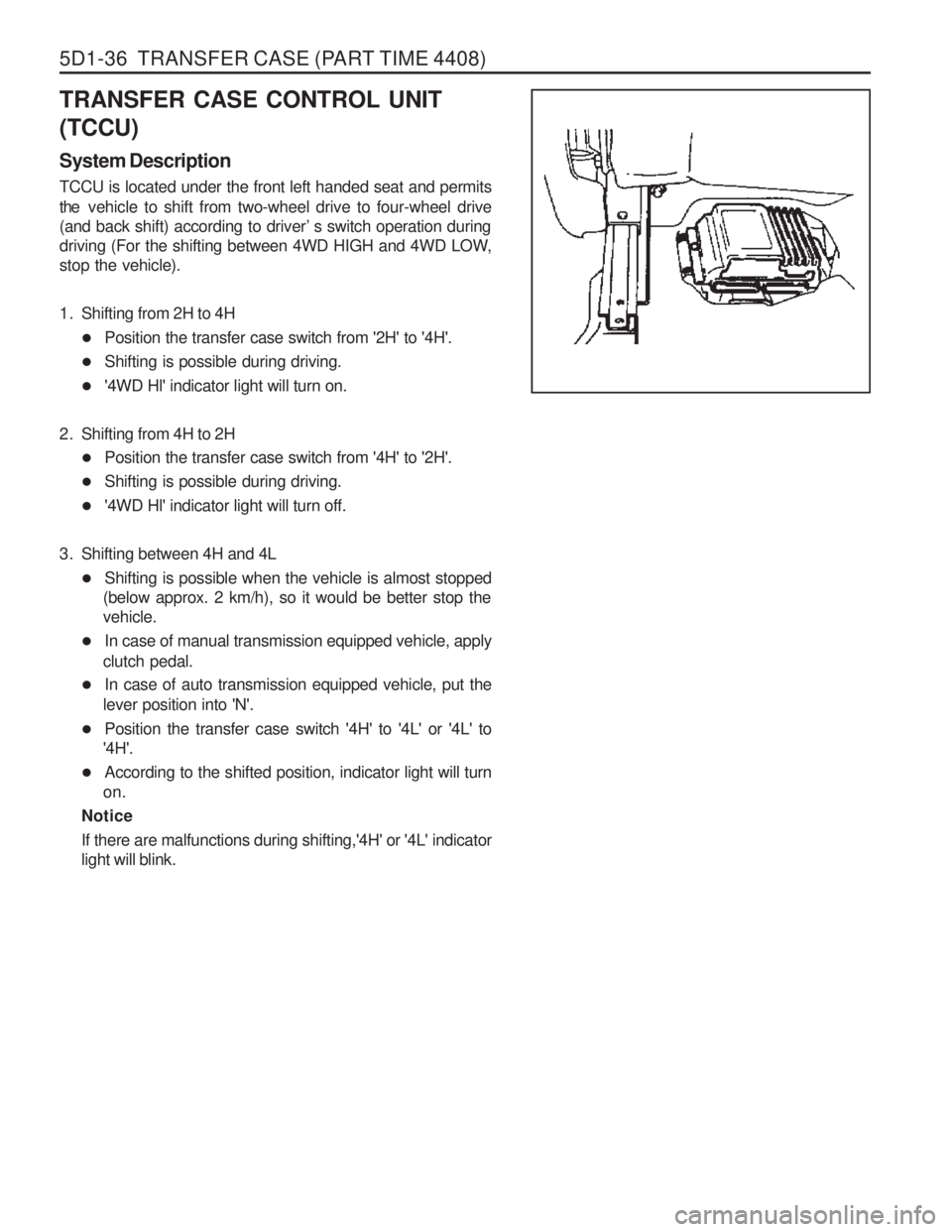
TRANSFER CASE CONTROL UNIT (TCCU) System Description TCCU is located under the front left handed seat and permits the vehicle to shift from two-wheel drive to four-wheel drive
(and back shift) according to driver ’s switch operation during
driving (For the shifting between 4WD HIGH and 4WD LOW, stop the vehicle).
1. Shifting from 2H to 4H
� Position the transfer case switch from '2H' to '4H'.
� Shifting is possible during driving.
� '4WD Hl' indicator light will turn on.
2. Shifting from 4H to 2H � Position the transfer case switch from '4H' to '2H'.
� Shifting is possible during driving.
� '4WD Hl' indicator light will turn off.
3. Shifting between 4H and 4L � Shifting is possible when the vehicle is almost stopped
(below approx. 2 km/h), so it would be better stop the vehicle.
� In case of manual transmission equipped vehicle, apply
clutch pedal.
� In case of auto transmission equipped vehicle, put the
lever position into 'N'.
� Position the transfer case switch '4H' to '4L' or '4L' to
'4H'.
� According to the shifted position, indicator light will turn
on.
Notice
If there are malfunctions during shifting,'4H' or '4L' indicator light will blink.
Page 1095 of 1574
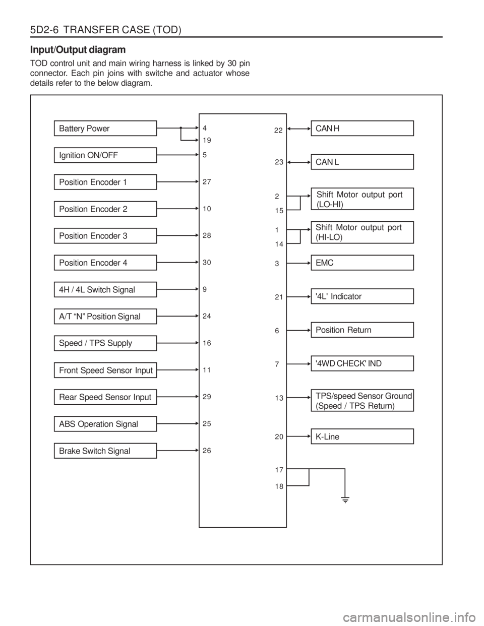
5D2-6 TRANSFER CASE (TOD) Input/Output diagram TOD control unit and main wiring harness is linked by 30 pin
connector. Each pin joins with switche and actuator whosedetails refer to the below diagram.
Battery Power
Ignition ON/OFF
Position Encoder 1
Position Encoder 2
Position Encoder 3
Position Encoder 4
4H / 4L Switch Signal
A/T “N” Position Signal
Speed / TPS Supply
Front Speed Sensor Input
Rear Speed Sensor Input
ABS Operation Signal
Brake Switch Signal
4 5271028309241611292526
19 CAN H
CAN L
Shift Motor output port (LO-HI)
Shift Motor output port (HI-LO)
EMC
'4L' Indicator
Position Return
'4WD CHECK' IND
TPS/speed Sensor Ground (Speed / TPS Return)
2 13216713
1514
K-Line
20
22
23
17 18
Page 1096 of 1574
TRANSFER CASE (TOD) 5D2-7
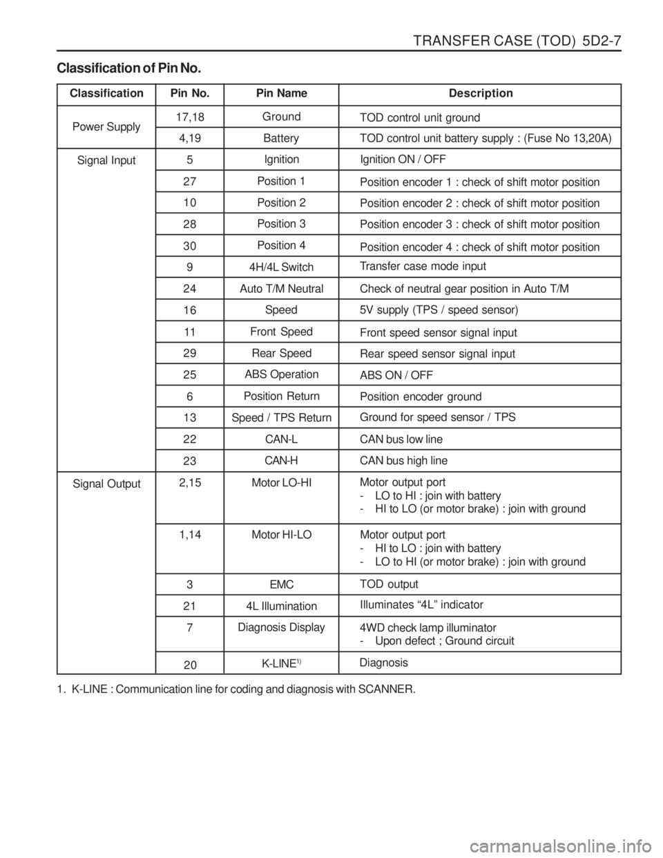
1. K-LINE : Communication line for coding and diagnosis with SCANNER.
Classification of Pin No.
Classification
Pin No. Pin Name Description
Power Supply 17,18
Ground
TOD control unit ground
4,19 Battery TOD control unit battery supply : (Fuse No 13,20A)
5 Ignition Ignition ON / OFF
27 Position 1
Position encoder 1 : check of shift motor position
10 Position 2 Position encoder 2 : check of shift motor position
28 Position 3
Position encoder 3 : check of shift motor position
30 Position 4
Position encoder 4 : check of shift motor position
9 4H/4L Switch Transfer case mode input
24 Auto T/M Neutral Check of neutral gear position in Auto T/M 16 Speed 5V supply (TPS / speed sensor)
11 Front Speed
Front speed sensor signal input
Signal Input
29 Rear Speed Rear speed sensor signal input
25 ABS Operation
ABS ON / OFF
6 Position Return
Position encoder ground
13 Speed / TPS Return Ground for speed sensor / TPS
2 2 CAN-L CAN bus low line
23 CAN-H
CAN bus high line
2,15 Motor LO-HI Motor output port
- LO to HI : join with battery
- HI to LO (or motor brake) : join with ground
1,14 Motor HI-LO Motor output port
- HI to LO : join with battery
- LO to HI (or motor brake) : join with ground
3 EMC TOD output
Signal Output
21 4L Illumination Illuminates
“4L ” indicator
7 Diagnosis Display
4WD check lamp illuminator
- Upon defect ; Ground circuit
20K-LINE1)
Diagnosis
Page 1097 of 1574
5D2-8 TRANSFER CASE (TOD)Position Code 1/2/3/4 111 0
1010 0010 0000 111 0
Initial Operation of TOD Control Unit When ignition
“ON ”, “4L ” and "4WD check" lamps illuminates
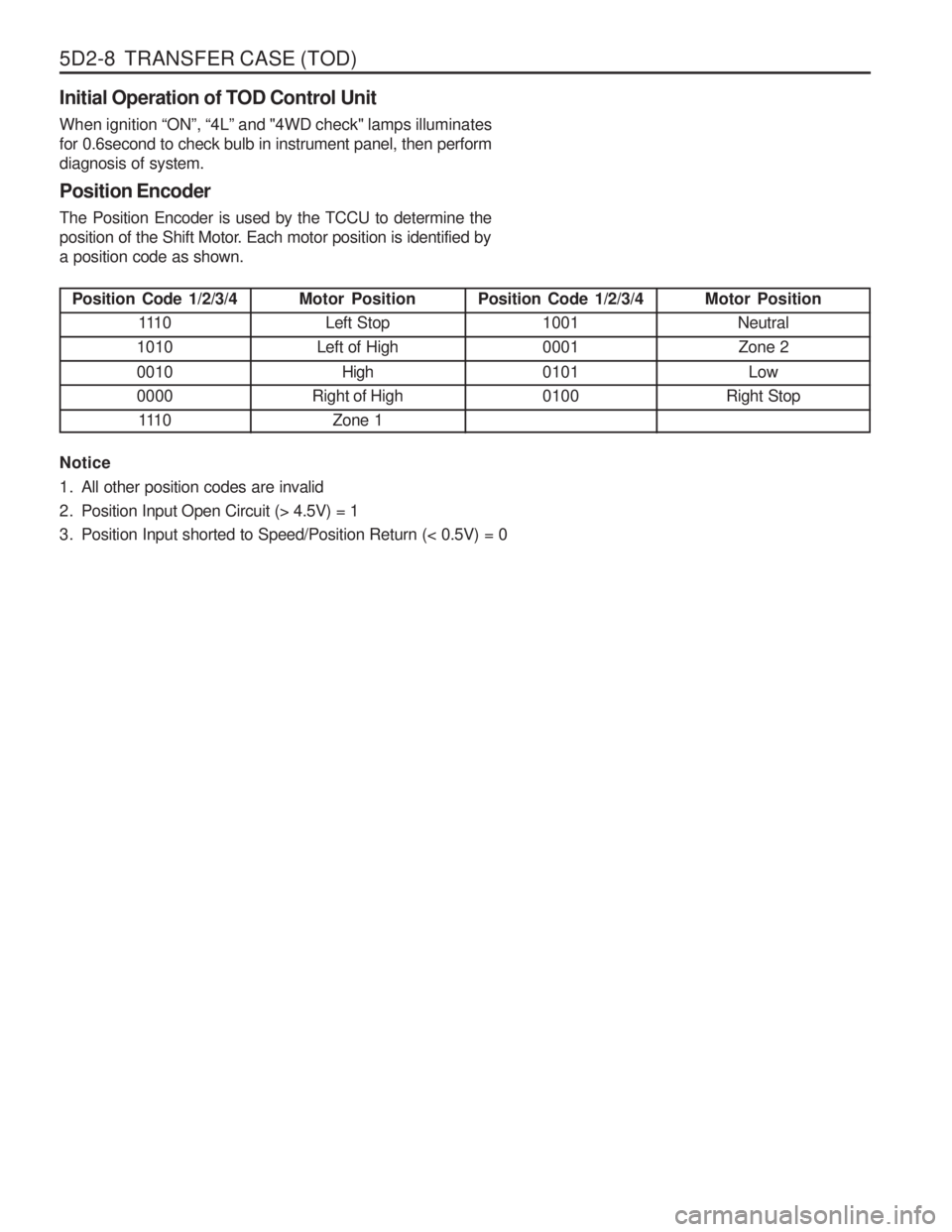
for 0.6second to check bulb in instrument panel, then perform diagnosis of system. Position Encoder The Position Encoder is used by the TCCU to determine the
position of the Shift Motor. Each motor position is identified bya position code as shown. Notice
1. All other position codes are invalid
2. Position Input Open Circuit (> 4.5V) = 1
3. Position Input shorted to Speed/Position Return (< 0.5V) = 0
Motor Position
Left Stop
Left of High
High
Right of High Zone 1 Position Code 1/2/3/4
1001 0001 0101 0100 Motor Position
NeutralZone 2
Low
Right Stop
Page 1100 of 1574
TRANSFER CASE (TOD) 5D2-11
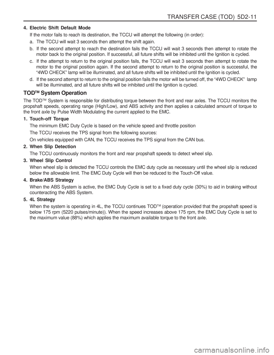
4. Electric Shift Default ModeIf the motor fails to reach its destination, the TCCU will attempt the following (in order):
a. The TCCU will wait 3 seconds then attempt the shift again.
b. If the second attempt to reach the destination fails the TCCU will wait 3 seconds then attempt to rotate the motor back to the original position. If successful, all future shifts will be inhibited until the Ignition is cycled.
c. If the attempt to return to the original position fails, the TCCU will wait 3 seconds then attempt to rotate the motor to the original position again. If the second attempt to return to the original position is successful, the “4WD CHECK ” lamp will be illuminated, and all future shifts will be inhibited until the Ignition is cycled.
d. If the second attempt to return to the original position fails the motor will be turned off, the “4WD CHECK ” lamp
will be illuminated, and all future shifts will be inhibited until the Ignition is cycled.
TOD TM
System Operation
The TOD TM
System is responsible for distributing torque between the front and rear axles. The TCCU monitors the
propshaft speeds, operating range (High/Low), and ABS activity and then applies a calculated amount of torque tothe front axle by Pulse Width Modulating the current applied to the EMC.
1. Touch-off Torque
The minimum EMC Duty Cycle is based on the vehicle speed and throttle positionThe TCCU receives the TPS signal from the following sources:On vehicles equipped with CAN, the TCCU receives the TPS signal from the CAN bus.
2. When Slip Detection
The TCCU continuously monitors the front and rear propshaft speeds to detect wheel slip.
3. Wheel Slip Control When wheel slip is detected the TCCU controls the EMC duty cycle as necessary until the wheel slip is reduced
below the allowable limit. The EMC Duty Cycle will then be reduced to the Touch-Off value.
4. Brake/ABS Strategy When the ABS System is active, the EMC Duty Cycle is set to a fixed duty cycle (30%) to aid in braking without counteracting the ABS System.
5. 4L Strategy When the system is operating in 4L, the TCCU continues TOD TM
(operation provided that the propshaft speed is
below 175 rpm (5220 pulses/minute)). When the speed increases above 175 rpm, the EMC Duty Cycle is set tothe maximum value (88%) which applies the maximum available torque to the front axle.
Page 1104 of 1574
TRANSFER CASE (TOD) 5D2-15
DIAGNOSIS
While the TCCU is active it periodically monitors its inputs and outputs. If a fault is detected the “4WD CHECK ” lamp
is illuminated and a fault code is stored in the TCCU memory.
When requested, fault codes are downloaded to a diagnostic connector (K-line) serial communications using SCAN- 100. DIAGNOSTIC TESTS 1.TCCU Internal Function
When the Ignition is turned on the TCCU tests its ROM and RAM. If there is a fault, the TCCU immediately resets itself and re-tests the ROM and RAM. If the fault persists the TCCU continues to reset and re-test until the fault is corrected or the ignition is turned off. All TCCU functions are inhibited until the fault is corrected. The “4WD
CHECK ” lamp is not illuminated if there is a ROM or RAM fault.
If the ROM/RAM passes the EEPROM memory is tested. If there is a fault the “4WD CHECK ” lamp is illuminated
and the TCCU continues to operate using the default calibration data stored in ROM. Fault codes are not storedwhen there is an EEPROM fault.
An EEPROM fault can only be cleared by cycling ignition off-on.
2.Shift Motor Assembly Test If the TCCU detects a shift motor or position encoder fault continuously for one second the ‘4WD CHECK ” lamp is
turned on and the appropriate fault code is stored in memory.
a. A shift motor fault when the motor is off is defined as follows:
Motor H-L shorted to GroundMotor L-H shorted to GroundMotor open circuit
b. A shift motor fault when the motor is energized is defined as follows: Motor H-L shorted to GroundMotor L-H shorted to GroundMotor H-L shorted to Motor L-H Motor open circuit
c. A position encoder fault is defined as follows: Any position code which does not correspond to the valid 9 codes. A short to ground on any of the encoder lines.
d. If no shifts are in progress when a failure occurs the TCCU will not respond to any shift commands.
e. If a shift command has been received, but not acted upon when a failure occurs the TCCU will cancel the command and not respond to any subsequent shift commands.
f. If a shift command is in progress when an invalid position code is confirmed it will be halted and the TCCU will turn the motor toward the high position. Afterwards the TCCU will not respond to any shift commands.
Page 1105 of 1574
5D2-16 TRANSFER CASE (TOD)g. If the shift motor/position encoder assembly failure (other than a motor failure which occurs when the motor isenergized) recovers continuously for one second the TCCU will function normally. The “4WD CHECK ” lamp is
turned off but the fault code will remain in memory.
h. A motor failure (i.e. open or short circuit) which occurs when the motor is energized can only be cleared by cycling the ignition off-on.
3. Front Speed Sensor Test If a Front Speed Sensor fault is detected continuously for 0.5 second the “4WD CHECK ” lamp is illuminated. The
TCCU then responds as follows:
a. If the system is in High Range the TCCU uses the Rear Speed Sensor to determine the EMC Touch Off level and wheel slip control is suspended.
b. If the system is in Low Range, the EMC Duty Cycle is set to maximum (independent of vehicle speed) until the system is shifted out of 4L.
c. All Electric Shift activity is halted until the Ignition is cycled. If a shift is in progress it will be completed.
If the Front Speed Sensor recovers continuously for O.5 second the TCCU will function normally. The “4WD
CHECK ” lamp is turned off but the fault code will remain in memory.
4. Rear Speed Sensor Test If a Rear Speed Sensor fault is detected continuously for 0.5 second the “4WD CHECK ” lamp is illuminated. The
TCCU then responds as follows:
a. If the system is in High Range the TCCU uses the Front Speed Sensor to determine the EMC Touch Off level and wheel slip control is suspended.
b. If the system is in Low Range, the EMC Duty Cycle is set to maximum (independent of vehicle speed) until the system is shifted out of 4L.
c. All Electric Shift activity is halted until the Ignition is cycled. If a shift is in progress it will be completed.
If the Rear Speed Sensor recovers continuously for 0.5 second the TCCU will function normally. The “4WD
CHECK ” lamp is turned off but the fault code will remain in memory.
5. Both Speed Sensor Faulty If both the Front and Rear Speed Sensors are faulty continuously for 0.5 seconds the “4WD CHECK ” lamp is
illuminated. The TCCU then responds as follows:
a. If the system is in High Range the TCCU sets the EMC Touch Off level based on a vehicle speed of 0 and wheel slip control is suspended.
b. If the system is in Low Range, the EMC Duty Cycle is set to maximum until the system is shifted out of 4L.
c. All Electric Shift activity is halted until the Ignition is cycled. If a shift is in progress it will be completed.
If both Speed Sensors recover continuously for 0.5 second the TCCU will function normally. The “4WD CHECK ”
lamp is turned off but the fault code will remain in memory.
6. EMC Test The EMC is tested for open circuit or short circuit to ground. If a fault is detected continuously for 0.8 second the “4WD CHECK ” lamp is turned on and all TOD TM
activity is halted.
If the EMC recovers continuously for 0.8 second the TCCU will function normally. The “4WD CHECK ” lamp is
turned off but the fault code will remain in memory.