battery SSANGYONG MUSSO 2003 Workshop Manual
[x] Cancel search | Manufacturer: SSANGYONG, Model Year: 2003, Model line: MUSSO, Model: SSANGYONG MUSSO 2003Pages: 1574, PDF Size: 26.41 MB
Page 583 of 1574

M162 ENGINE CONTROLS 1F1-51
Removal & Installation Procedure
1. Discharge the fuel pressure from the fuel pressure testconnector.
2. Disconnect the battery ground cable.
3. Disconnect the vacuum hose from the fuel pressure regulator.
4. Remove the cable guide.
5. Remove the fuel return and supply line.
Notice
� For removal, cover around parts with cloths not to be
stained by fuel.
� In case of checking the injector only, do not remove the
fuel return and supply line.
Installation Notice
6. Remove the six injector connectors.
7. Remove the two left and two right bolts and one center bolt of the fuel distributor assembly from the intake manifold. Installation Notice
Tightening Torque 25 - 30 Nm
Tightening Torque 22.5 - 27.5 Nm
Page 592 of 1574

1F1-60 M162 ENGINE CONTROLS
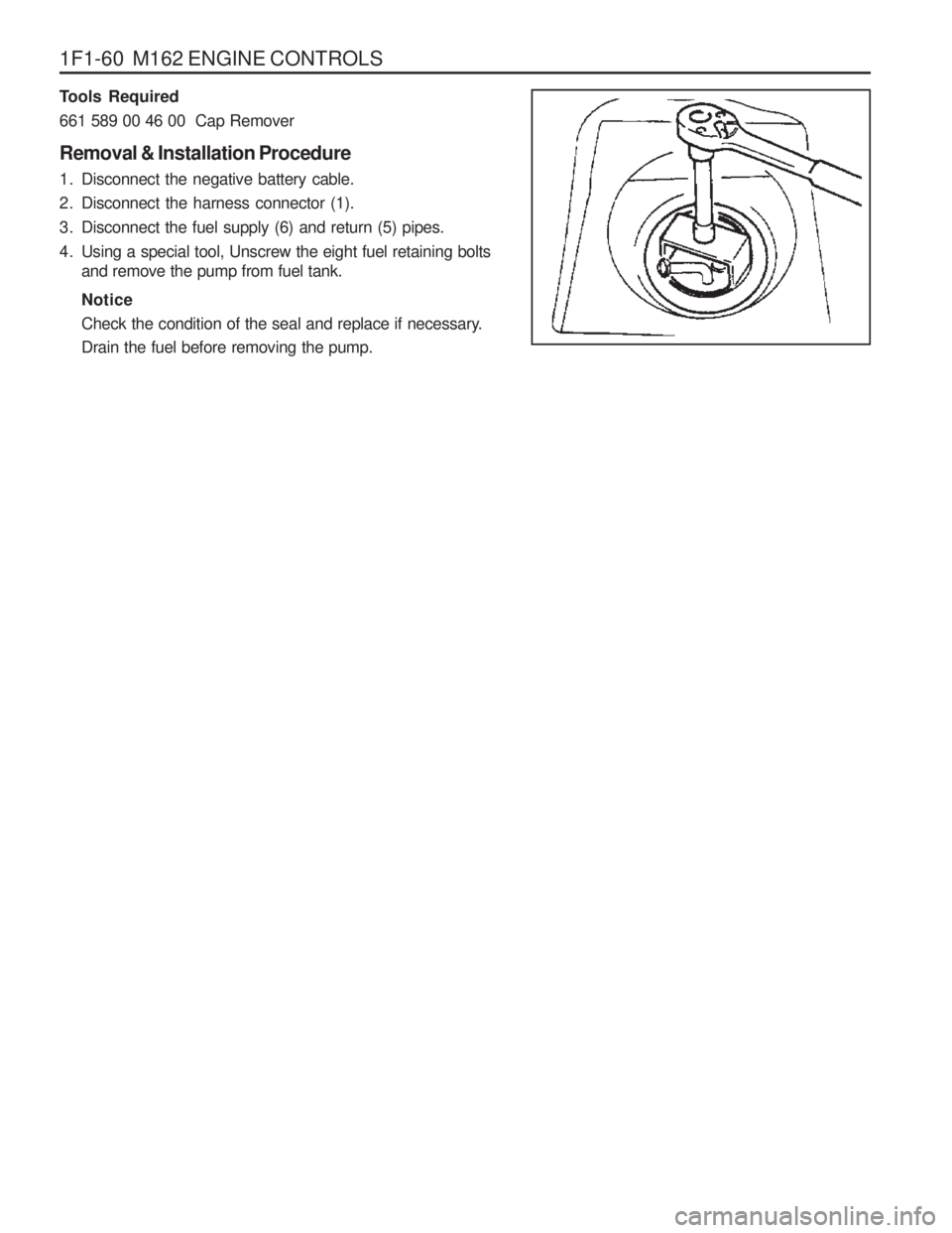
Tools Required 661 589 00 46 00 Cap Remover Removal & Installation Procedure
1. Disconnect the negative battery cable.
2. Disconnect the harness connector (1).
3. Disconnect the fuel supply (6) and return (5) pipes.
4. Using a special tool, Unscrew the eight fuel retaining boltsand remove the pump from fuel tank. Notice
Check the condition of the seal and replace if necessary. Drain the fuel before removing the pump.
Page 612 of 1574

SECTION 1F3
OM600 ENGINE CONTROLS
Specifications . . . . . . . . . . . . . . . . . . . . . . . 1F3-1Fastener Tightening Specifications . . . . . . . . 1F3-1
Maintenance and Repair . . . . . . . . . . . . . . 1F3-2
On-Vehicle Service . . . . . . . . . . . . . . . . . . . . 1F3-2
Fuel System . . . . . . . . . . . . . . . . . . . . . . . . . 1F3-2
Fuel Injection Pump Coding . . . . . . . . . . . . . 1F3-3
Fuel Tank . . . . . . . . . . . . . . . . . . . . . . . . . . . 1F3-4
Vacuum Control System Test . . . . . . . . . . . . 1F3-5
Vacuum Pump(Sectional View) . . . . . . . . . . 1F3-10
Vacuum Pump Test . . . . . . . . . . . . . . . . . . . 1F3-11
Vacuum Pump . . . . . . . . . . . . . . . . . . . . . . 1F3-13
Vacuum Unit Replacement . . . . . . . . . . . . . 1F3-15Idle Speed Adjustment . . . . . . . . . . . . . . . .
1F3-16
Fuel Pump Test . . . . . . . . . . . . . . . . . . . . . . 1F3-18
Fuel Pump . . . . . . . . . . . . . . . . . . . . . . . . . 1F3-21
Injection Nozzle Test . . . . . . . . . . . . . . . . . . 1F3-22
Injection Nozzles . . . . . . . . . . . . . . . . . . . . . 1F3-25
Injection Nozzle Repair . . . . . . . . . . . . . . . . 1F3-27
Removal and Installation of Injection Timing Device . . . . . . . . . . . . . . 1F3-30
Injection Timing Device . . . . . . . . . . . . . . . . 1F3-35
Start of Delivery Test (Position Sensor, RIV Method) . . . . . . . . . 1F3-37
Fuel Injection Pump . . . . . . . . . . . . . . . . . . 1F3-46
TABLE OF CONTENTS
Caution: Disconnect the negative battery cable before removing or installing any electrical unit or when a tool or equipment could easily come in contact with exposed electrical terminals. Disconnecting this cable will help prevent personal injury and damage to the vehicle. The ignition must also be in LOCK unless otherwisenoted.
SPECIFICATIONS
FASTENER TIGHTENING SPECIFICATIONS
Application
Fuel Tank Mounting Nut Fuel Pump Pressure Line Fuel Injection NozzleFuel Injection Pipe
Nozzle Tensioning NutScrew Plug Left-Hand Thread Bolt
N· m
28 - 47 13
35 - 40 18 8030 46
Page 647 of 1574

OM600 ENGINE CONTROLS 1F3-37
START OF DELIVERY TEST (POSITION SENSOR, RIV METHOD)1 Position Sensor
2 Battery
3 Fuel Injection Pump 4 Seal
....................................................... Replace
5 Screw Plug ................................................. 30Nm
Service Data
Start of Delivery (RIV) ATDC 14° - 16 °
Page 648 of 1574

1F3-38 OM600 ENGINE CONTROLS
Tools Required 617 589 08 21 00 Position Sensor
Test Procedure
1. Remove the screw plug (5) and seal (4) and collect oil in a suitable vessel.
2. Install the position sensor (1) into the governor housing of
the injection pump to be the guide pin of the position sensor facing up.
3. Connect the battery terminal of position sensor (1) to positive terminal (+) of battery.
Position Sensor 617 589 08 21 00
4. Rotate the crankshaft by hand (in direction of engine rotation) until the lamp ‘B’ lights up. Rotate the crankshaft carefully
further until both lamps ‘A and B ’ come on. In this position,
check the Rl value on the crankshaft vibration damper. Notice If only lamp ‘A’ lights up, repeat the test and if out of
specification, adjust start of delivery.
Specification A TDC 14° - 16 °
Page 649 of 1574

OM600 ENGINE CONTROLS 1F3-39
Digital Tester, RIV Method
(Connection Diagram for Testers Without Adapter)
1 Fuel Injection Pump
2 Rl Sensor
3 Digital Tester4 TDC Pulse Sender Unit
5 Battery
Page 650 of 1574

1F3-40 OM600 ENGINE CONTROLSStart of Delivery (RIV) Idle Speed
(Connection Diagram for Testers With Adapter)
1 Fuel Injection Pump
2 Rl Sensor
3 Digital Tester
4 TDC Pulse Sender Unit
5 Battery
6 Rl Pulse Generator
Service Data
ATDC 14° - 16 °
OM661LA : 720 - 820 rpm, OM662LA : 750 - 850 rpm
Page 680 of 1574

1G2-8 M161 ENGINE INTAKE & EXHAUST
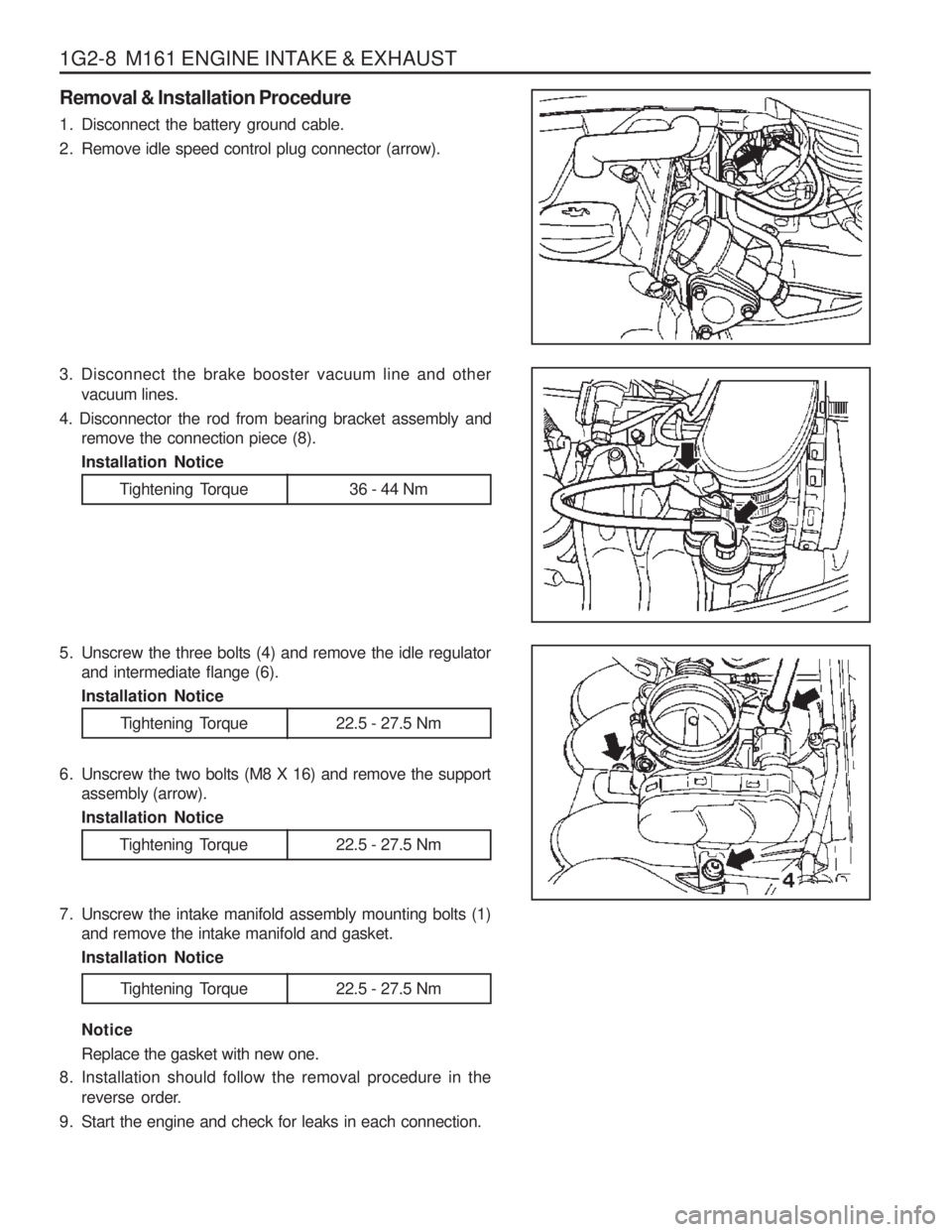
Removal & Installation Procedure
1. Disconnect the battery ground cable.
2. Remove idle speed control plug connector (arrow).
3. Disconnect the brake booster vacuum line and othervacuum lines.
4. Disconnector the rod from bearing bracket assembly and remove the connection piece (8). Installation Notice
Tightening Torque 36 - 44 Nm
5. Unscrew the three bolts (4) and remove the idle regulatorand intermediate flange (6). Installation Notice
Tightening Torque 22.5 - 27.5 Nm
6. Unscrew the two bolts (M8 X 16) and remove the support assembly (arrow). Installation Notice
7. Unscrew the intake manifold assembly mounting bolts (1) and remove the intake manifold and gasket.Installation Notice Notice Replace the gasket with new one.
8. Installation should follow the removal procedure in the reverse order.
9. Start the engine and check for leaks in each connection.
Tightening Torque 22.5 - 27.5 Nm
Tightening Torque 22.5 - 27.5 Nm
Page 684 of 1574

SECTION 1G3
OM600 ENGINE INTAKE & EXHAUST
Specifications . . . . . . . . . . . . . . . . . . . . . . . 1G3-1Fastener Tightening Specifications . . . . . . . . 1G3-1
Schematic and Routing Diagrams . . . . . . . 1G3-2 EGR Circuit . . . . . . . . . . . . . . . . . . . . . . . . . . 1G3-2
Maintenance and Repair . . . . . . . . . . . . . . 1G3-3
On-Vehicle Service . . . . . . . . . . . . . . . . . . . . 1G3-3 TABLE OF CONTENTS
Caution: Disconnect the negative battery cable before removing or installing any electrical unit or when a tool or equipment could easily come in contact with exposed electrical terminals. Disconnecting this cable will help prevent personal injury and damage to the vehicle. The ignition must also be in LOCK unless otherwisenoted.
SPECIFICATIONS
FASTENER TIGHTENING SPECIFICATIONS
Application
Air Cleaner Housing Cover Nut Intake Manifold Bolt (M8 x 20)Intake Manifold Bolt (M8)Exhaust Mainfold Stud BoltExhaust Pipe Nut (Engine) Exhaust Pipe Bolt
N
m
9 - 11
22.5 - 27.5 22.5 - 27.5 9.5 - 12.5 15 - 2828 - 47
Air Cleaner and Inlet Duct & Hose . . . . . . . . 1G3-3
Intake and Exhaust Manifold . . . . . . . . . . . . . 1G3-5
Turbocharger . . . . . . . . . . . . . . . . . . . . . . . 1G3-8
Charge Air System Diagram . . . . . . . . . . . . . 1G3-8
Intercooler . . . . . . . . . . . . . . . . . . . . . . . . . . 1G3-9
Turbocharger Assembly . . . . . . . . . . . . . . . 1G3-11
Page 705 of 1574

2A-8 SUSPENSION DIAGNOSIS-
ACTUATOR INSPECTION Output position of the actuator should be changed as below when battery voltage is applied between actuator connector terminals.
Connector
terminal Battery Voltage
Position of The Actuator Output Remark
1 (White)
-
2 (Black)
OPEN
3 (Red) +
1 (White) +
2 (Black) -
3 (Red)
OPEN
1 (White) OPEN
2 (Black) +
3 (Red) SOFT Mode
MEDIUM Mode
HARD Mode