ABS SSANGYONG MUSSO 2003 Service Manual
[x] Cancel search | Manufacturer: SSANGYONG, Model Year: 2003, Model line: MUSSO, Model: SSANGYONG MUSSO 2003Pages: 1574, PDF Size: 26.41 MB
Page 3 of 1574

GENERAL INFORMATION 0B-3
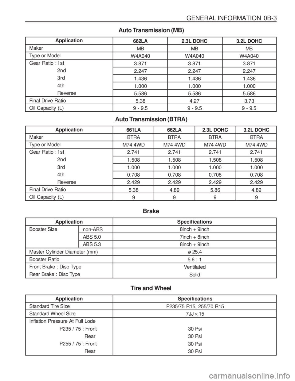
662LA MB
W4A040 3.871 2.247 1.4361.0005.5865.38
9 - 9.5
Auto Transmission (MB)
Application
Maker
Type or Model
Gear Ratio : 1st 2nd3rd 4th Reverse
Final Drive RatioOil Capacity (L)
2.3L DOHC MB
W4A040 3.871 2.247 1.4361.0005.5864.27
9 - 9.5 3.2L DOHC
MB
W4A040 3.871 2.247 1.4361.0005.5863.73
9 - 9.5
661LA
BTRA
M74 4WD
2.741 1.508 1.0000.7082.429
5.38 9
Auto Transmission (BTRA)
Application
Maker
Type or Model
Gear Ratio : 1st 2nd 3rd 4thReverse
Final Drive RatioOil Capacity (L)662LA BTRA
M74 4WD
2.741 1.508 1.0000.7082.429
4.89 9 2.3L DOHC
BTRA
M74 4WD
2.741 1.508 1.0000.7082.429
5.86 9 3.2L DOHC
BTRA
M74 4WD
2.741 1.508 1.0000.7082.429
4.89 9
Tire and Wheel
Specifications
P235/75 R15, 255/70 R15 7JJ × 15
30 Psi 30 Psi 30 Psi 30 Psi
Application
Standard Tire SizeStandard Wheel SizeInflation Pressure At Full Lode
P235 / 75 : FrontRear
P255 / 75 : Front Rear
Application
Booster Size Master Cylinder Diameter (mm) Booster Ratio
Front Brake : Disc Type
Rear Brake : Disc Type
Specifications 8inch + 9inch 7inch + 8inch 8inch + 9inch
� 25.4
5.6 : 1
Ventilated
Solid
Brake
non-ABS ABS 5.0ABS 5.3
Page 153 of 1574

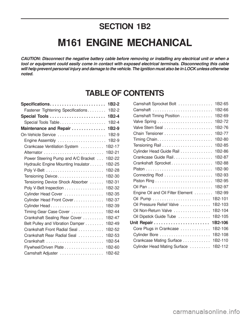
SECTION 1B2
M161 ENGINE MECHANICAL
CAUTION: Disconnect the negative battery cable before removing or installing any electrical unit or when a tool or equipment could easily come in contact with exposed electrical terminals. Disconnecting this cable will help prevent personal injury and damage to the vehicle. The ignition must also be in LOCK unless otherwisenoted.
Specifications . . . . . . . . . . . . . . . . . . . . . . . 1B2-2Fastener Tightening Specifications . . . . . . . . 1B2-2
Special Tools . . . . . . . . . . . . . . . . . . . . . . . 1B2-4 Special Tools Table . . . . . . . . . . . . . . . . . . . . 1B2-4
Maintenance and Repair . . . . . . . . . . . . . . 1B2-9
On-Vehicle Service . . . . . . . . . . . . . . . . . . . . . 1B2-9
Engine Assembly . . . . . . . . . . . . . . . . . . . . . 1B2-9
Crankcase Ventilation System . . . . . . . . . . 1B2-17
Alternator . . . . . . . . . . . . . . . . . . . . . . . . . . 1B2-21
Power Steering Pump and A/C Bracket . . . 1B2-22
Hydraulic Engine Mounting Insulator . . . . . . 1B2-25
Poly V-Belt . . . . . . . . . . . . . . . . . . . . . . . . . 1B2-28
Tensioning Deivce . . . . . . . . . . . . . . . . . . . . 1B2-30
Tensioning Device Shock Absorber . . . . . . 1B2-31
Poly V-Belt Inspection . . . . . . . . . . . . . . . . . 1B2-32
Cylinder Head Cover . . . . . . . . . . . . . . . . . 1B2-35
Cylinder Head Front Cover . . . . . . . . . . . . . 1B2-37
Cylinder Head . . . . . . . . . . . . . . . . . . . . . . . 1B2-39
Timing Gear Case Cover . . . . . . . . . . . . . . 1B2-44
Crankshaft Sealing Rear Cover . . . . . . . . . 1B2-47
Belt Pulley and Vibration Damper . . . . . . . . 1B2-49
Crankshaft Front Radial Seal . . . . . . . . . . . 1B2-52
Crankshaft Rear Radial Seal . . . . . . . . . . . 1B2-53
Crankshaft . . . . . . . . . . . . . . . . . . . . . . . . . 1B2-54
Flywheel/Driven Plate . . . . . . . . . . . . . . . . . 1B2-60
Camshaft Adjuster . . . . . . . . . . . . . . . . . . . 1B2-62
TABLE OF CONTENTS
Camshaft Sprocket Bolt . . . . . . . . . . . . . . . 1B2-65
Camshaft . . . . . . . . . . . . . . . . . . . . . . . . . . 1B2-66
Camshaft Timing Position . . . . . . . . . . . . . . 1B2-69
Valve Spring . . . . . . . . . . . . . . . . . . . . . . . . 1B2-72
Valve Stem Seal . . . . . . . . . . . . . . . . . . . . . 1B2-76
Chain Tensioner . . . . . . . . . . . . . . . . . . . . . 1B2-77
Timing Chain . . . . . . . . . . . . . . . . . . . . . . . . 1B2-80
Tensioning Rail . . . . . . . . . . . . . . . . . . . . . . 1B2-85
Cylinder Head Guide Rail . . . . . . . . . . . . . . 1B2-86
Crankcase Guide Rail . . . . . . . . . . . . . . . . . 1B2-87
Crankshaft Sprocket . . . . . . . . . . . . . . . . . . 1B2-88
Piston . . . . . . . . . . . . . . . . . . . . . . . . . . . . . 1B2-90
Connecting Rod . . . . . . . . . . . . . . . . . . . . . 1B2-93
Piston Ring . . . . . . . . . . . . . . . . . . . . . . . . . 1B2-95
Oil Pan . . . . . . . . . . . . . . . . . . . . . . . . . . . . 1B2-97
Engine Oil and Oil Filter Element . . . . . . . . 1B2-99
Oil Pump . . . . . . . . . . . . . . . . . . . . . . . . . 1B2-101
Oil Pressure Relief Valve . . . . . . . . . . . . . 1B2-103
Oil Non-Return Valve . . . . . . . . . . . . . . . . 1B2-104
Oil Dipstick Guide Tube . . . . . . . . . . . . . . 1B2-105
Unit Repair . . . . . . . . . . . . . . . . . . . . . . . 1B2-106 Core Plugs in Crankcase . . . . . . . . . . . . . 1B2-106
Cylinder Bore . . . . . . . . . . . . . . . . . . . . . . 1B2-108
Crankcase Mating Surface . . . . . . . . . . . . 1B2-110
Cylinder Head Mating Surface . . . . . . . . . 1B2-112
Page 182 of 1574

1B2-30 M161 ENGINE MECHANICAL TENSIONING DEVICE Preceding Work : Removal of tensioning device shock absorber
1 Bolt (M8 x 75, 2 pieces) +Washer .......................................... 22.5-27.5 Nm
2 Bolt (M8 x 25, 1 pieces) + Washer .......................................... 22.5-27.5 Nm
Removal & Installation Procedure
1. Turn the stud bolt to counterclockwise.
2. Insert the pin (111 589 01 15 00) into the hole in tensioning arm.
3. Unscrew the bolts (1, 2) and remove the tensioning device.
Installation Notice
4. Installation should follow the removal procedure in the reverse order. 3 Tensioning Device
4 Stud bolt
5 Tensioning Arm
Tightening Torque 22.5 - 27.5 Nm
Page 183 of 1574

M161 ENGINE MECHANICAL 1B2-31
TENSIONING DEVICE SHOCK ABSORBER
1 End Cover
2 Nut .................................................40.5-49.5 Nm
3 Tensioning Pulley
4 Bolt (M8 X 25) + Washer ................22.5-27.5 Nm
Removal & Installation Procedure
1. Remove the end cover (1).
2. Remove the nut (2) and remove the tensioning pulley (3). Installation Notice 5 Tensioning Device
6 Bolt (M8 X 35) + Washer
................22.5-27.5 Nm
7 Shock Absorber
Tightening Torque 40.5 - 49.5 Nm
3. Unscrew the bolts (4,6) and remove the shock absorber (7). Installation Notice
Tightening Torque 22.5-27.5 Nm
Page 479 of 1574

1D2-12 M161 ENGINE COOLING
THERMOSTAT HOUSING ASSEMBLY Preceding Work : Removal of viscous clutch
1a Bolt (M6 X 95, 2 pieces)......................... 9-11 Nm
1b Bolt (M8 X 75, 2 pieces) .................22.5-27.5 Nm
1 c Bolt (M8 X 35, 1 piece) ...................22.5-27.5 Nm
2 Thermostat Housing Assembly
3 O-ring 4 De-aeration Hose
5 Coolant Outlet Hose
6 Coolant Bypass Hose
7 Tensioning Device Shock Absorber
8 Engine Hanger Brocket
Page 480 of 1574

M161 ENGINE COOLING 1D2-13
Removal & Installation Procedure
1. Drain the coolant.
2. Remove the de-aeration hose (4), coolant outlet hose (5) and coolant bypass hose (6).
3. Disconnect the coolant temperature sensor connector.
4. Unscrew the bolt (1c) and pry off the tensioning device shock absorber (7).Installation Notice
6. Replace the O-ring with new one.
7. Installation should follow the removal procedure in the reverse order.
8. Check for leaks in cooling system.
5. Unscrow the bolts (1a, 1b) and remove the engine
hanger bracket and thermostat housing.Installation Notice
Tightening Torque 9 - 11 Nm
22.5 - 27.5 Nm
(1a) (1b)
Tightening Torque 22.5 - 27.5 Nm
Page 538 of 1574

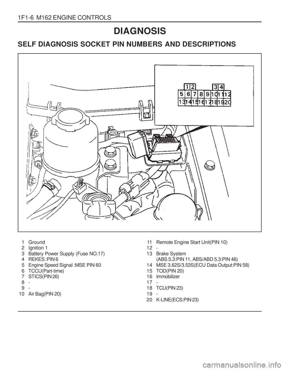
1F1-6 M162 ENGINE CONTROLSDIAGNOSIS
SELF DIAGNOSIS SOCKET PIN NUMBERS AND DESCRIPTIONS
1 Ground
2 Ignition 1
3 Battery Power Supply (Fuse NO.17)
4 REKES :PIN 6
5 Engine Speed Signal :MSE PIN 60
6 TCCU(Part-time)
7 STICS(PIN 26) 8- 9-
10 Air Bag(PIN 20) 11 Remote Engine Start Unit(PIN 10)
12 -
13 Brake System (ABS 5.3:PIN 11, ABS/ABD 5.3:PIN 46)
14 MSE 3.62S/3.53S(ECU Data Output:PIN 58)
15 TOD(PIN 20)
1 6 Immobilizer
17 -
18 TCU(PIN 23)
19 -
2 0 K-LINE(ECS:PIN 23)
Page 551 of 1574

M162 ENGINE CONTROLS 1F1-19
Failurecode Item
�
22.1
Checking method
Test stepRequirementSpecified
value Possible cause
38 37 115 - 125
�
CAN module
resistance in ABS, ABD,ASR controlunit
Cable
ABS, ABD, ASR
control unit Ignition:OFF
- disconnect the coupling "No.1" from ECU.
� 22.2
38 37 115 - 125
�
CAN module
resistance inECU controlunit
ECU Ignition:OFF
- disconnect the coupling "No.1" from ECU.
� 23.0
558 11 - 14 V
Diagnosis
cable operating ECU
Cable
Ignition:ON
22,23, 24,26,27,29,30,31,59,60,
Page 577 of 1574

M162 ENGINE CONTROLS 1F1-45
Removal & Installation Procedure
�when removing the ECU only
1. Turn the ignition switch to "OFF" position.
2. Disconnect the negative battery cable.
3. Disconnect the couplings from ECU.
4. Unscrew the left and right bolt (3) on bolt (1) and auxiliarly bracket and remove the auxiliarly bracket from the bracket assembly (2). Installation Notice
5. Unscrew the four bolts (5) and disconnect the ECU (6) from the bracket assenbly. Installation Notice
6. Installation should follow the removal procedure in the reverse order.
Tightening Torque 6 - 8 Nm
5 - 7 Nm(1) (3)
Tightening Torque 5 - 7 Nm
8. Unscrew the bolts (5) and disconnect the ECU (6) from the bracket assenbly. Installation Notice
�
When Removing the ECU with ABS or ABS/ASR Unit
1. Turn the ignition switch to "OFF" position.
2. Disconnect the negative battery cable.
3. Disconnect the couplings from ECU.
4. Disconnect the coupling from ABS or ABS/ASR unit.
5. Unscrew the bolt (1) and the left and right flange nuts.
6. Remove the ECU with ABS or ABS/ASR unit assembly.
7. Unscrew the left and right bolt (3) on the auxiliary bracket and remove the auxiliary bracket from the bracket assembly. Installation Notice
Tightening Torque 6 - 8 Nm
Tightening Torque 5 - 7 Nm
Tightening Torque 5 - 7 Nm
9. Installation should follow the removal procedure in the reverse order.
Page 594 of 1574

1F1-62 M162 ENGINE CONTROLS
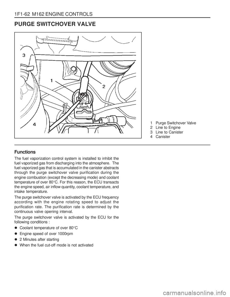
PURGE SWITCHOVER VALVE
1 Purge Switchover Valve
2 Line to Engine
3 Line to Canister
4 Canister
Functions The fuel vaporization control system is installed to inhibit the fuel vaporized gas from discharging into the atmosphere. Thefuel vaporized gas that is accumulated in the canister abstractsthrough the purge switchover valve purification during the engine combustion (except the decreasing mode) and coolant temperature of over 80 °C. For this reason, the ECU transacts
the engine speed, air inflow quantity, coolant temperature, andintake temperature. The purge switchover valve is activated by the ECU frequency according with the engine rotating speed to adjust the purification rate. The purification rate is determined by the continuous valve opening interval. The purge switchover valve is activated by the ECU for the following conditions :
� Coolant temperature of over 80 °C
� Engine speed of over 1000rpm
� 2 Minutes after starting
� When the fuel cut-off mode is not activated