air conditioning SSANGYONG MUSSO 2003 Service Manual
[x] Cancel search | Manufacturer: SSANGYONG, Model Year: 2003, Model line: MUSSO, Model: SSANGYONG MUSSO 2003Pages: 1574, PDF Size: 26.41 MB
Page 12 of 1574

0B-12 GENERAL INFORMATIONOWNER INSPECTIONS AND SERVICES
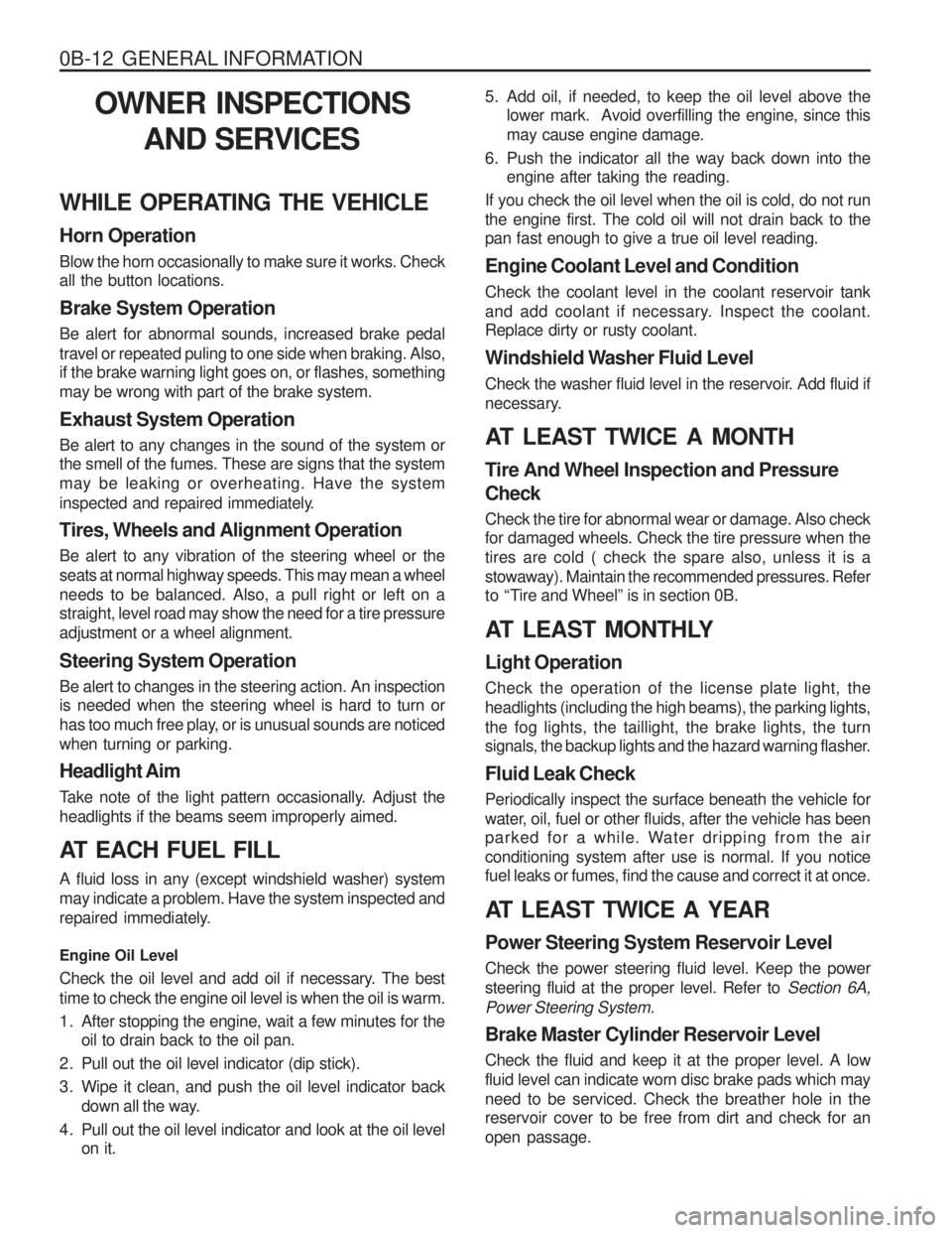
WHILE OPERATING THE VEHICLE Horn Operation Blow the horn occasionally to make sure it works. Check all the button locations. Brake System Operation Be alert for abnormal sounds, increased brake pedal travel or repeated puling to one side when braking. Also, if the brake warning light goes on, or flashes, something may be wrong with part of the brake system. Exhaust System Operation Be alert to any changes in the sound of the system or the smell of the fumes. These are signs that the system may be leaking or overheating. Have the system
inspected and repaired immediately. Tires, Wheels and Alignment Operation Be alert to any vibration of the steering wheel or the seats at normal highway speeds. This may mean a wheelneeds to be balanced. Also, a pull right or left on a straight, level road may show the need for a tire pressure adjustment or a wheel alignment. Steering System Operation Be alert to changes in the steering action. An inspection is needed when the steering wheel is hard to turn or
has too much free play, or is unusual sounds are noticedwhen turning or parking. Headlight Aim
Take note of the light pattern occasionally. Adjust the headlights if the beams seem improperly aimed.
AT EACH FUEL FILL A fluid loss in any (except windshield washer) system may indicate a problem. Have the system inspected and
repaired immediately. Engine Oil Level
Check the oil level and add oil if necessary. The best time to check the engine oil level is when the oil is warm.
1. After stopping the engine, wait a few minutes for the oil to drain back to the oil pan.
2. Pull out the oil level indicator (dip stick).
3. Wipe it clean, and push the oil level indicator back down all the way.
4. Pull out the oil level indicator and look at the oil level on it. 5. Add oil, if needed, to keep the oil level above the
lower mark. Avoid overfilling the engine, since this may cause engine damage.
6. Push the indicator all the way back down into the engine after taking the reading.
If you check the oil level when the oil is cold, do not runthe engine first. The cold oil will not drain back to the pan fast enough to give a true oil level reading. Engine Coolant Level and Condition Check the coolant level in the coolant reservoir tank
and add coolant if necessary. Inspect the coolant. Replace dirty or rusty coolant.
Windshield Washer Fluid Level
Check the washer fluid level in the reservoir. Add fluid if
necessary.
AT LEAST TWICE A MONTH Tire And Wheel Inspection and Pressure Check Check the tire for abnormal wear or damage. Also check for damaged wheels. Check the tire pressure when the tires are cold ( check the spare also, unless it is astowaway). Maintain the recommended pressures. Refer
to “Tire and Wheel” is in section 0B.
AT LEAST MONTHLY Light Operation Check the operation of the license plate light, the headlights (including the high beams), the parking lights,the fog lights, the taillight, the brake lights, the turn
signals, the backup lights and the hazard warning flasher. Fluid Leak Check Periodically inspect the surface beneath the vehicle for
water, oil, fuel or other fluids, after the vehicle has been
parked for a while. Water dripping from the air conditioning system after use is normal. If you notice fuel leaks or fumes, find the cause and correct it at once.
AT LEAST TWICE A YEAR Power Steering System Reservoir Level Check the power steering fluid level. Keep the power steering fluid at the proper level. Refer to Section 6A,
Power Steering System. Brake Master Cylinder Reservoir Level Check the fluid and keep it at the proper level. A low fluid level can indicate worn disc brake pads which mayneed to be serviced. Check the breather hole in the reservoir cover to be free from dirt and check for an open passage.
Page 13 of 1574

GENERAL INFORMATION 0B-13
Weather-Strip Lubrication Apply a thin film silicone grease using a clean cloth. EACH TIME THE OIL IS CHANGED Brake System Inspection This inspection should be done when the wheels are removed for rotation. Inspect the lines and the hoses for proper hookup, binding, leaks, cracks, chafing, etc.
Inspect the disc brake pads for wear. Inspect the rotors for surface condition. Inspect other brake parts, theparking brake, etc., at the same time. Inspect the brakes more often if habit or conditions result in frequent braking. Steering, Suspension and Front Drive Axle Boot And Seal Inspection Inspect the front and rear suspension and the steering system for damaged, loose or missing parts, signs of wear or lack of lubrication. Inspect the power steering line and the hoses for proper hookup, binding, leaks, cracks, chafing, etc. Clean and inspect the drive axle boot and seals for damage, tears or leakage. Replace
the seals if necessary. Exhaust System Inspection Inspect the complete system (including the catalytic converter if equipped). Inspect the body near the exhaustsystem. Look for broken, damaged, missing, or out-of- position parts as well as open seams, holes, loose connections, or other conditions which could cause heat buildup in the floor pan or could let exhaust fumes seep into the trunk or passenger compartment. Throttle Linkage Inspection Inspect the throttle linkage for interference or binding, damaged, or missing parts. Lubricate all linkage joints and throttle cable joints, the intermediate throttle shaft
bearing, the return spring at throttle valve assembly, and the accelerator pedal sliding face with suitable grease. Check the throttle cable for free movements. Engine Drive Belts Inspect all belts for cracks, fraying, wear and proper tension. Adjust or replace the belts as needed. Hood Latch Operation When opening the hood, note the operation of the secondary latch. It should keep the hood from opening all the way when the primary latch is released. The hood
must close firmly. AT LEAST ANNUALLY Lap and Shoulder Belts Condition and Operation Inspect the belt system including: the webbing, the
buckles, the latch plates, the retractor, the guide loops and the anchors. Movable Head Restraint Operation On vehicles with movable head restraints, the restraints must stay in the desired position. Spare Tire and Jack Storage Be alert to rattles in the rear of the vehicle. The spare tire, all the jacking equipment, and the tools must besecurely stowed at all times. Oil the jack ratchet or the screw mechanism after each use. Key Lock Service
Lubricate the key lock cylinder. Body Lubrication Service Lubricate all the body door hinges including the hood,
the fuel door, the rear compartment hinges and the latches, the glove box and the console doors, and anyfolding seat hardware. Underbody Flushing Flushing the underbody will remove any corrosive materials used for ice and snow removal and dust control.
At least every spring clean the underbody. First, loosen the sediment packed in closed areas of the vehicle. Then
flush the underbody with plain water. Engine Cooling System Inspect the coolant and freeze protection fluid. If the fluid
is dirty or rusty, drain, flush and refill the engine cooling system with new coolant. Keep the coolant at the propermixture in order to ensure proper freeze protection, corrosion protection and engine operating temperature. Inspect the hoses. Replace the cracked, swollen, or
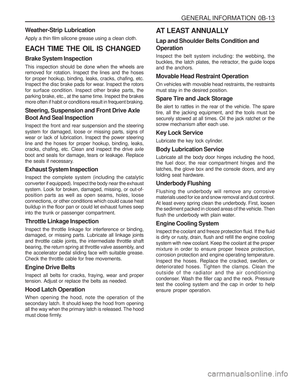
deteriorated hoses. Tighten the clamps. Clean the outside of the radiator and the air conditioning
condenser. Wash the filler cap and the neck. Pressure test the cooling system and the cap in order to help ensure proper operation.
Page 570 of 1574

1F1-38 M162 ENGINE CONTROLS
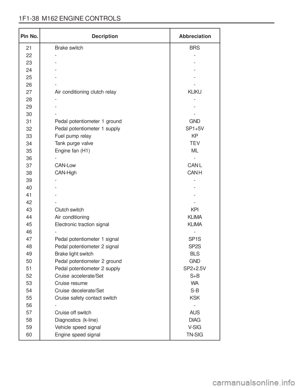
Pin No.Abbreciation
Decription
21 222324252627282930313233343536373839404142434445464748495051525354555657585960 BRS
-----
KLIKU ---
GND
SP1+5V KP
TEV ML -
CAN L
CAN H -- - -
KPI
KLIMAKLIMA -
SP1SSP2S BLS
GND
SP2+2.5V S+BWA
S-B
KSK -
AUS
DIAG
V-SIG
TN-SIG
Brake switch-----Air conditioning clutch relay---Pedal potentiometer 1 groundPedal potentiometer 1 supplyFuel pump relay
Tank purge valveEngine fan (H1)-CAN-LowCAN-High-- - -Clutch switchAir conditioningElectronic traction signal-Pedal potentiometer 1 signalPedal potentiometer 2 signalBrake light switchPedal potentiometer 2 groundPedal potentiometer 2 supplyCruise accelerate/SetCruise resumeCruise decelerate/SetCruise safety contact switch-Cruise off switchDiagnostics (k-line)
Vehicle speed signalEngine speed signal
Page 573 of 1574

M162 ENGINE CONTROLS 1F1-41
Application
Pin No.Description
- Starter motor TM.50- - Electronic ground--- Lambda probe 1 heating Power ground TM.31
V-BATTERY TM.87
V-BATTERY TM.30Immobilizer crypto read Immobilizer crypto write -Lambda probe 1 groundLambda probe 1 signal- - -Brake switch-- - --Air conditioning clutch relay- - -1 23 4 5678 9
10 11
12 13 14 15161718 19 20212223 24 25262728 29 30-
TM.50 - -
GND - --
LSH1
TM.31TM.87TM.30
WFS I/O WFS O
-
GND LS1 - - -
BRS -- - --
KLIKU - - - -
� --
� -- -
�
�
�
�
�
� -
�
� - - -
� -- - --
� - - - -
� - -
� - --
�
�
�
�
�
�
-
�
� - - -
� -- - --
� - - -
� : Standard, �: Option Remarks
Abbreviation E32 ENG,
5speed M/T
E32 ENG,
4speed A/T (BTRA)
Page 574 of 1574

1F1-42 M162 ENGINE CONTROLS
Pin No.Description
Pedal potentiometer 1 ground Pedal potentiometer 1 supplyFuel pump relay
Tank purge valve Engine fan -CAN-LowCAN-High - - --Clutch switchAir conditioning Electronic traction signal(ABD) -Pedal potentiometer 1 signalPedal potentiometer 2 signalBrake light switchPedal potentiometer 2 ground Pedal potentiometer 2 supply Cruise accelerate/SetCruise resumeCruise decelerate/SetCruise safety contact switch - Cruise off switchDiagnostics(K-line)
Vehicle speed signalEngine speed signal31 323334 35 363738 39 40 41424344 45 4647484950 51 52535455 56 57585960GND
SP1+5V KP
TEV ML
-
CAN L
CAN H
- - --
KPL
KLIMA ETS
-
SP1SSP2S BLS
GND
SP2+2.5V
S+BWA
S-B
KSK -
AUS
DIAG
V-SIG
TN-SIG �
�
�
�
�
-
�
� - - --
� �
�
-
�
�
� �
�
�
�
�
� -
� �
�
� �
�
�
�
�
-
�
� - - --
� �
�
-
�
�
� �
�
�
�
�
� -
� �
�
� Remarks
Abbreviation E32 ENG,
5speed M/T
E32 ENG,
4speed A/T (BTRA)
Page 1157 of 1574

SECTION 7D
FULL AUTOMATIC TEMPERATURECONTROL HEATING, VENTILATION AND AIR CONDITIONING SYSTEM
Specifications . . . . . . . . . . . . . . . . . . . . . . . . 7D-1 Specifications . . . . . . . . . . . . . . . . . . . . . . . . . 7D-1
Service Specifications . . . . . . . . . . . . . . . . . . . 7D-3
Schematic and Routing Diagrams . . . . . . . . 7D-4
Circuit Diagram . . . . . . . . . . . . . . . . . . . . . . . . 7D-4
FATC Block Diagram . . . . . . . . . . . . . . . . . . . . 7D-5
Component Locator . . . . . . . . . . . . . . . . . . . 7D-6 TABLE OF CONTENTS
Ventilation System . . . . . . . . . . . . . . . . . . . . . . 7D-6
Function Description . . . . . . . . . . . . . . . . . . . . 7D-7
Diagnosis . . . . . . . . . . . . . . . . . . . . . . . . . . . 7D-8
Diagnosis Test . . . . . . . . . . . . . . . . . . . . . . . . 7D-8
Maintenance and Repair . . . . . . . . . . . . . . 7D-11 FATC Control Panel . . . . . . . . . . . . . . . . . . . 7D-11
Troubleshooting . . . . . . . . . . . . . . . . . . . . . . 7D-15
FATC (Full Automatic Temperature Control) is full automatic heater and airconditioning system that detects incar temperature, ambient temperature, sun load and coolant temperature and controls airconditioner system
blowing capacity, outlet temperature and intaking/outlet mode to maintain interior comfort.
SPECIFICATIONSSPECIFICATIONS
Application
Core Size (LxWxT)
Core Type
Expansion Valve Type Thermostat
Resister TypeCooling Capacity Description
237.0x232.0x92.0 Aluminum plate
Angle
ON:4.5±0.6 °C, OFF:1.5±0.6 °C
Aluminum plate
4,500 Kcal/h(AT 420 CMH)
Evaporator Unit
Application
Capacity
Type Description
650-750 g R134a
Refrigerant