cruise control SSANGYONG MUSSO 2003 Service Manual
[x] Cancel search | Manufacturer: SSANGYONG, Model Year: 2003, Model line: MUSSO, Model: SSANGYONG MUSSO 2003Pages: 1574, PDF Size: 26.41 MB
Page 540 of 1574
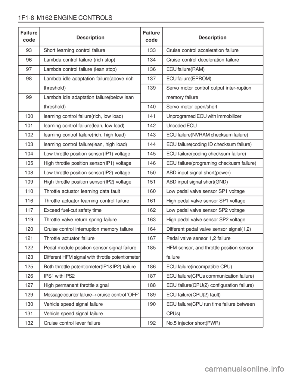
1F1-8 M162 ENGINE CONTROLSCruise control acceleration failure Cruise control deceleration failureECU failure(RAM)ECU failure(EPROM) Servo motor control output inter-ruption memory failureServo motor open/shortUnprogramed ECU with Immobilizer Uncoded ECU ECU failure(NVRAM checksum failure) ECU failure(coding ID checksum failure)ECU failure(coding checksum failure)ECU failure(programing checkusm failure)ABD input signal short(power) ABD input signal short(GND) Low pedal valve sensor SP1 voltageHigh pedal valve sensor SP1 voltageLow pedal valve sensor SP2 voltageHigh pedal valve sensor SP2 voltageDifferent pedal valve sensor signal(1,2) Pedal valve sensor 1,2 failure
HFM sensor, and throttle position sensorfailureECU failure(incompatible CPU)ECU failure(CPUs communication failure) ECU failure(CPU(2) configuration failure) ECU failure(CPU(2) fault)ECU failure(CPU run time failure betweenCPUs)No.5 injector short(PWR)
93969798 99
100 101 102 103 104 105108 109 11 0
11 6
11 7
11 9
120 121 122123125126 127 129130131132 Short learning control failureLambda control failure (rich stop)Lambda control failure (lean stop) Lambda idle adaptation failure(above rich threshold) Lambda idle adaptation failure(below lean threshold)learning control failure(rich, low load)learning control failure(lean, low load) learning control failure(rich, high load) learning control failure(lean, high load)Low throttle position sensor(IP1) voltageHigh throttle position sensor(IP1) voltageLow throttle position sensor(IP2) voltage High throttle position sensor(IP2) voltage Throttle actuator learning data faultThrottle actuator learning control failureExceed fuel-cut safety timeThrottle valve return spring failureCruise control interruption memory failure Throttle actuator failure Pedal module position sensor signal failureDifferent HFM signal with throttle potentiometerBoth throttle potentiometer(IP1&IP2) failureIPS1 with IPS2 High permanent throttle signal Message counter failure
� cruise control ’OFF ’
Vehicle speed signal failure
Vehicle speed signal failureCruise control lever failure 133134 136 137 139 140 141142 143 144145146150 151 160161162163164 167 185 186 187 188 189190 192
Failure
code DescriptionFailure
code Description
Page 570 of 1574
1F1-38 M162 ENGINE CONTROLS
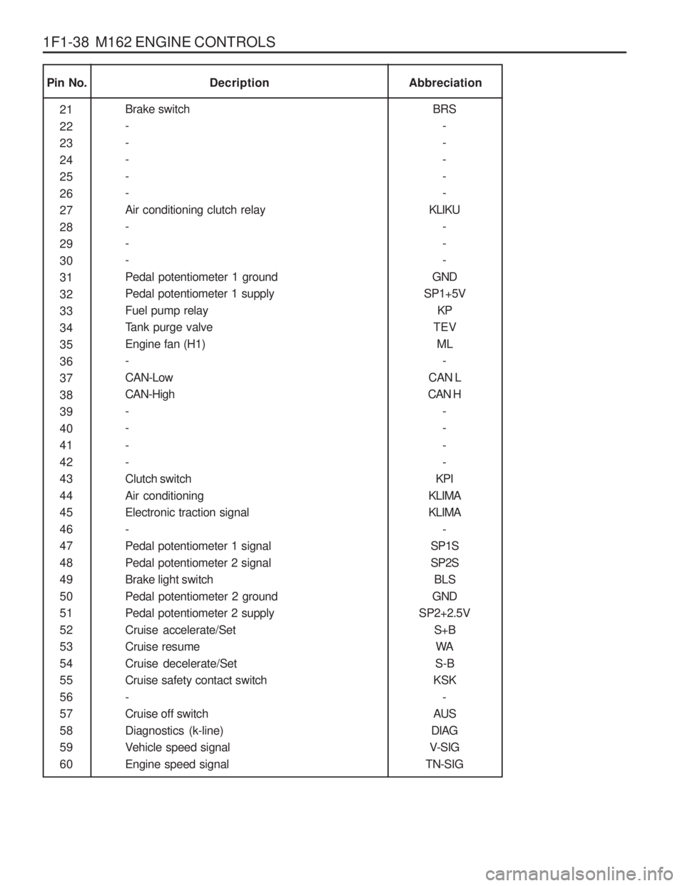
Pin No.Abbreciation
Decription
21 222324252627282930313233343536373839404142434445464748495051525354555657585960 BRS
-----
KLIKU ---
GND
SP1+5V KP
TEV ML -
CAN L
CAN H -- - -
KPI
KLIMAKLIMA -
SP1SSP2S BLS
GND
SP2+2.5V S+BWA
S-B
KSK -
AUS
DIAG
V-SIG
TN-SIG
Brake switch-----Air conditioning clutch relay---Pedal potentiometer 1 groundPedal potentiometer 1 supplyFuel pump relay
Tank purge valveEngine fan (H1)-CAN-LowCAN-High-- - -Clutch switchAir conditioningElectronic traction signal-Pedal potentiometer 1 signalPedal potentiometer 2 signalBrake light switchPedal potentiometer 2 groundPedal potentiometer 2 supplyCruise accelerate/SetCruise resumeCruise decelerate/SetCruise safety contact switch-Cruise off switchDiagnostics (k-line)
Vehicle speed signalEngine speed signal
Page 574 of 1574

1F1-42 M162 ENGINE CONTROLS
Pin No.Description
Pedal potentiometer 1 ground Pedal potentiometer 1 supplyFuel pump relay
Tank purge valve Engine fan -CAN-LowCAN-High - - --Clutch switchAir conditioning Electronic traction signal(ABD) -Pedal potentiometer 1 signalPedal potentiometer 2 signalBrake light switchPedal potentiometer 2 ground Pedal potentiometer 2 supply Cruise accelerate/SetCruise resumeCruise decelerate/SetCruise safety contact switch - Cruise off switchDiagnostics(K-line)
Vehicle speed signalEngine speed signal31 323334 35 363738 39 40 41424344 45 4647484950 51 52535455 56 57585960GND
SP1+5V KP
TEV ML
-
CAN L
CAN H
- - --
KPL
KLIMA ETS
-
SP1SSP2S BLS
GND
SP2+2.5V
S+BWA
S-B
KSK -
AUS
DIAG
V-SIG
TN-SIG �
�
�
�
�
-
�
� - - --
� �
�
-
�
�
� �
�
�
�
�
� -
� �
�
� �
�
�
�
�
-
�
� - - --
� �
�
-
�
�
� �
�
�
�
�
� -
� �
�
� Remarks
Abbreviation E32 ENG,
5speed M/T
E32 ENG,
4speed A/T (BTRA)
Page 877 of 1574
5A-18 AUTOMATIC TRANSMISSIONINTRODUCTION
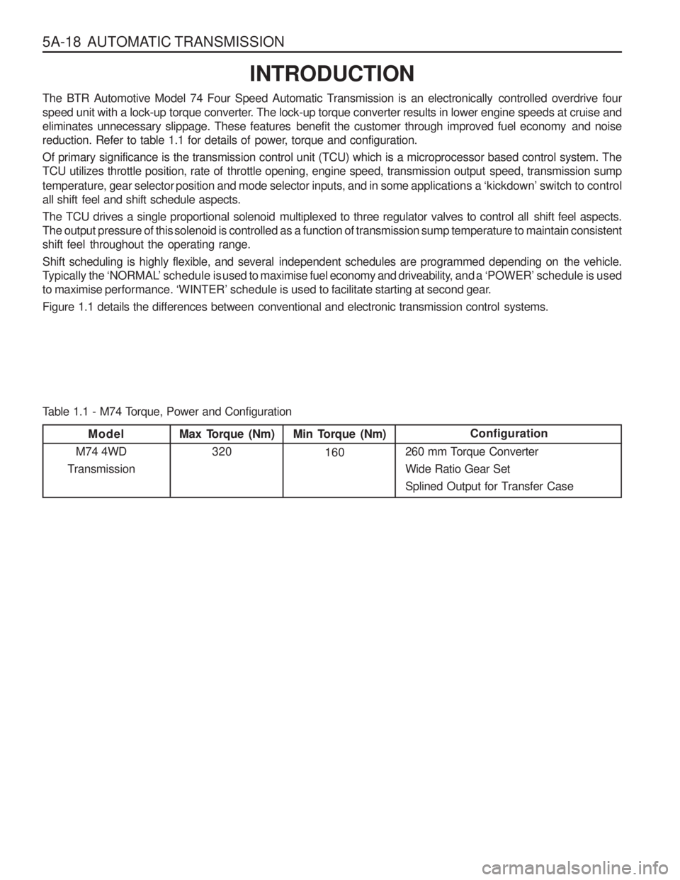
The BTR Automotive Model 74 Four Speed Automatic Transmission is an electronically controlled overdrive four
speed unit with a lock-up torque converter. The lock-up torque converter results in lower engine speeds at cruise and
eliminates unnecessary slippage. These features benefit the customer through improved fuel economy and noise
reduction. Refer to table 1.1 for details of power, torque and configuration.
Of primary significance is the transmission control unit (TCU) which is a microprocessor based control system. The
TCU utilizes throttle position, rate of throttle opening, engine speed, transmission output speed, transmission sump
temperature, gear selector position and mode selector inputs, and in some applications a ‘kickdown’ switch to control
all shift feel and shift schedule aspects.
The TCU drives a single proportional solenoid multiplexed to three regulator valves to control all shift feel aspects.
The output pressure of this solenoid is controlled as a function of transmission sump temperature to maintain consistent
shift feel throughout the operating range.
Shift scheduling is highly flexible, and several independent schedules are programmed depending on the vehicle.
Typically the ‘NORMAL’ schedule is used to maximise fuel economy and driveability, and a ‘POWER’ schedule is used
to maximise performance. ‘WINTER’ schedule is used to facilitate starting at second gear.
Figure 1.1 details the differences between conventional and electronic transmission control systems.
Max Torque (Nm)
320 Configuration
260 mm Torque Converter Wide Ratio Gear Set
Splined Output for Transfer CaseMin Torque (Nm) 160
Model
M74 4WD
Transmission
Table 1.1 - M74 Torque, Power and Configuration
Page 1399 of 1574
5-32 ELECTRICAL WIRING DIAGRAMS
4) VSS, CLUTCH SWITCH, IMMOBILIZER CIRCUIT(1) W/O EURO III
1
13
37
36
60
23456789101112
61
73
97
96
120
62 63 64 65 66 67 68 69 70 71 72
ECM(MSE)
DLC Connector - Main Main Main MainMain Main
C211 (14Pin, Black) S201 (Black)
S205 (Colorless) G201 G202 G205
b. CONNECTOR IDENTIFICATION SYMBOL & PIN NUMBER POSITION
a. CONNECTOR INFORMATION
VSSIMMOBILIZER
UNIT DLC
C211
W/H DLC
STOP LAMP SWITCH
CONNECTOR(NUMBER) CONNECTING. WIRING HARNESSCONNECTOR POSITION
Beside The Steering Column Behind The Cluster Upper Left The AudioRight The I/P Fuse Block Beside The STICS Beside The TCCU
1234
141516 13 12 11 10 9
8765432112
3
CLUTCH
SWITCH 1
2112
34
CRUISE
CONTROL SWITCH
12
3456
910 1213
12
11
34
56
71 4
8
15 IGN 1
31 GND
G205
BrB
BRG202
LR
G201
S201
Cruise Control Switch
1
7
BrW Y
VSS
(M/T)
59 55YB
Y 5
F24
2
1 LW
BrWBrB BrW
S205BrB
3
3 2
57
Gr
4
52
13
43 12 2 1
14 43 49 21 29 58 60
ECM
GY
WB
W
Y
RGBr
YW BrBGY
YR
5
54
YGr
6
7
2
53 38 37
BR
BrB
"L"CAN "H"CAN BrW
1
3 6
15
10A
TOD
"A11"
"7"
DLC
Stop Lamp
Switch"4"
Clutch Switch(M/T) Stop Lamp
Switch
"2"
"7"
OVPR
"86"
Fuel Pump Relay "33"
Cluster (MIL) "29"
Cluster (RPM)
TCM
"A24" TCM
"A23"
TOD
"A11"
"16"
Cluster
Immobilizer C211
14
SIG
SIG SIG
5V
Read
Page 1401 of 1574
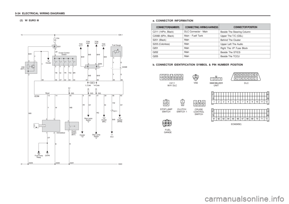
5-34 ELECTRICAL WIRING DIAGRAMS(2) W/ EURO III
1
13
37
36
60
23456789101112
61
73
97
96
120
62 63 64 65 66 67 68 69 70 71 72
ECM(MSE)
DLC Connector - Main Main - Fuell Tank Main MainMain Main Main
C211 (14Pin, Black)C206B (6Pin, Black) S201 (Black) S205 (Colorless) G201 G202G205
b. CONNECTOR IDENTIFICATION SYMBOL & PIN NUMBER POSITION
a. CONNECTOR INFORMATION
VSSIMMOBILIZER
UNIT DLC
C211
W/H DLC
STOP LAMP SWITCH
CONNECTOR(NUMBER) CONNECTING. WIRING HARNESSCONNECTOR POSITION
Beside The Steering Column Upper The T/C (GSL) Behind The ClusterUpper Left The Audio Right The I/P Fuse Block Beside The STICS Beside The TCCU
1234
141516 13 12 11 10 9
8765432112
3
CLUTCH
SWITCH 1
2112
34
CRUISE
CONTROL SWITCH
12
3456
5
40 56 1
YG Y
Fuel Gauge
GC206B
6
1
15 IGN 1
31 GND
G205
BrB
BRG202
LR
G201
S201
Cruise Control Switch
1
7
BrW Y
VSS
(M/T)
59 55YB
Y 5
F24
2
1 LW
BrWBrB BrW
S205BrB
3
3 2
57
Gr
4
52
13
43 12 2 1
14 43 49 21 29 58 60
ECM
GY
WB
W
Y
RGBr
YW BrBGY
YR
5
54
YGr
6
7
2
53 38 37
BR
BrB
"L"CAN "H"CAN BrW
1
3 6
15
10A
TOD
"A11"
"7"
DLC
8
RY
Cluster "15" Stop Lamp
Switch"4"
Clutch Switch(M/T) Stop Lamp
Switch
"2"
"7"
OV PR
"86"
Fuel Pump Relay "33"
Cluster
(MIL) "29"
Cluster
(RPM)
TCM
"A24" TCM
"A23"
TOD
"A11"
"16"
Cluster
Immobilizer C211
14
SIG
SIG SIG
5V
Read
910 1213
12
11
34
56
71 4
8
FUEL
GANGE
321
654
Page 1413 of 1574
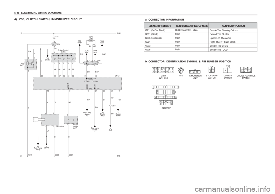
5-46 ELECTRICAL WIRING DIAGRAMS
4) VSS, CLUTCH SWITCH, IMMOBILIZER CIRCUITDLC Connector - Main Main Main MainMain Main
C211 (14Pin, Black) S201 (Black) S205 (Colorless) G201 G202 G205
b. CONNECTOR IDENTIFICATION SYMBOL & PIN NUMBER POSITION
a. CONNECTOR INFORMATION
VSSIMMOBILIZER
UNIT
C211
W/H DLC STOP LAMP
SWITCH
CONNECTOR(NUMBER) CONNECTING. WIRING HARNESSCONNECTOR POSITION
Baside The Steering Column Behind The Cluster Upper Left The AudioRight The I/P Fuse Block Beside The STICS Beside The TCCU
123412
3
CLUTCHSWITCH
12
34
CRUISE CONTROL SWITCH
12
3456
11 2
29 38
28
13 2021
39 434842
CLUSTER
15
IGN 1
31 GND
G205
B
BBG202
LR
G201
S201
Cruise Control Switch
1
7
BrW Y
VSS
(M/T)
59 55YB
Y 5
F24
2
1 LW
BrB BrW
S205
LY Y W
(M/T) CAN
3
3 2
57
Gr
4
52
13
43 12 2 1
14 43 49 21 29 58 60
ECM
GY
WB
W
Y
RGBr
YW BrBGY
YR
5
54
YGr
6
7
42
53 38 37
BR
BrB
"L"CAN "H"CAN BrW
1
386
15
10A
TOD
"A10"
"7"
DLC
Stop Lamp
Switch"4"
Clutch Switch(M/T) Stop Lamp
Switch"2"
"7"
OVPR
"86"
Fuel Pump Relay "33"
Cluster (MIL) "2"
Cluster (RPM)
TCM
"A24" TCM
"A23"
TOD
"A11"
"16"
Cluster
Immobilizer C211
14
SIG
SIG SIG
5V
910 1213
12
11
34
56
71 4
8