fuse SSANGYONG MUSSO 2003 Service Manual
[x] Cancel search | Manufacturer: SSANGYONG, Model Year: 2003, Model line: MUSSO, Model: SSANGYONG MUSSO 2003Pages: 1574, PDF Size: 26.41 MB
Page 319 of 1574
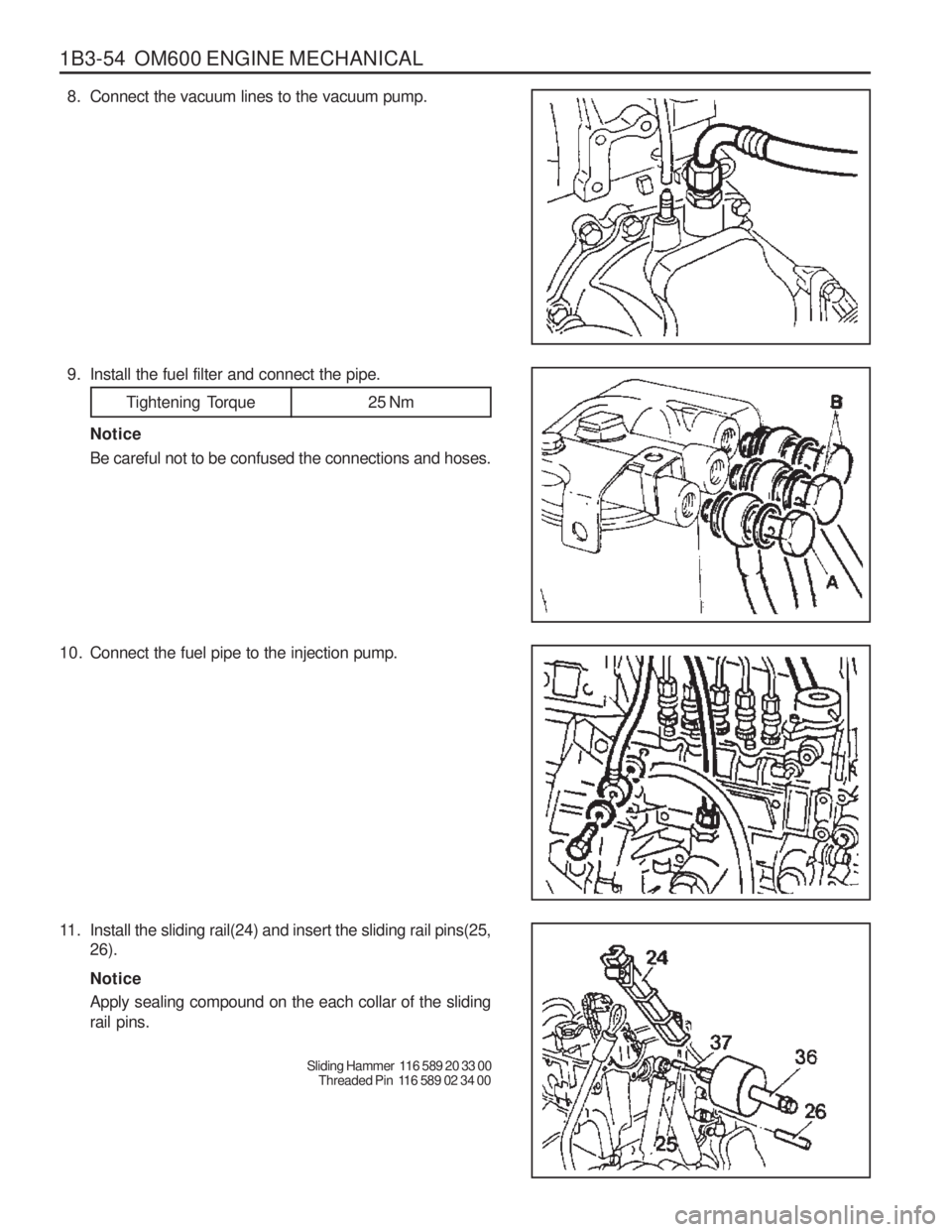
1B3-54 OM600 ENGINE MECHANICAL8. Connect the vacuum lines to the vacuum pump.
9. Install the fuel filter and connect the pipe.
Tightening Torque 25 Nm
Notice Be careful not to be confused the connections and hoses.
10. Connect the fuel pipe to the injection pump.
11. Install the sliding rail(24) and insert the sliding rail pins(25, 26). Notice Apply sealing compound on the each collar of the sliding rail pins.
Sliding Hammer 116 589 20 33 00Threaded Pin 116 589 02 34 00
Page 506 of 1574
1E1-6 M162 ENGINE ELECTRICAL
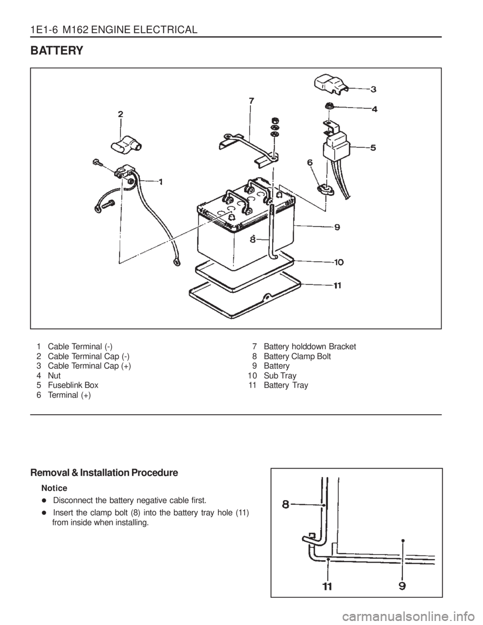
BATTERY
1 Cable Terminal (-)
2 Cable Terminal Cap (-)
3 Cable Terminal Cap (+)
4 Nut
5 Fuseblink Box
6 Terminal (+)7 Battery holddown Bracket
8 Battery Clamp Bolt
9 Battery
10 Sub Tray 11 Battery Tray
Removal & Installation Procedure Notice
� Disconnect the battery negative cable first.
� Insert the clamp bolt (8) into the battery tray hole (11)
from inside when installing.
Page 518 of 1574
1E2-6 M161 ENGINE ELECTRICAL
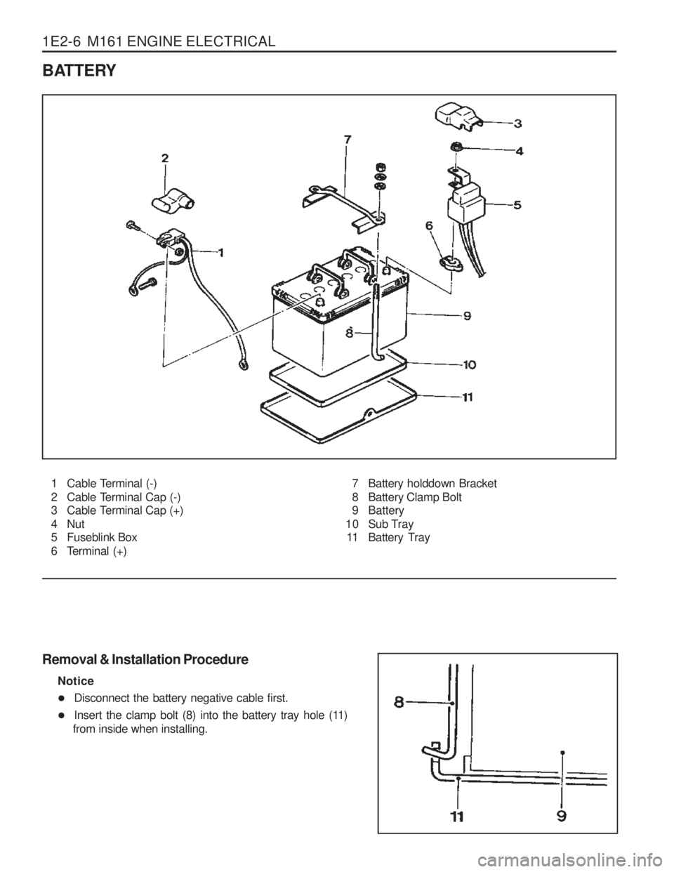
BATTERY
1 Cable Terminal (-)
2 Cable Terminal Cap (-)
3 Cable Terminal Cap (+)
4 Nut
5 Fuseblink Box
6 Terminal (+)7 Battery holddown Bracket
8 Battery Clamp Bolt
9 Battery
10 Sub Tray 11 Battery Tray
Removal & Installation Procedure Notice
� Disconnect the battery negative cable first.
� Insert the clamp bolt (8) into the battery tray hole (11)
from inside when installing.
Page 538 of 1574
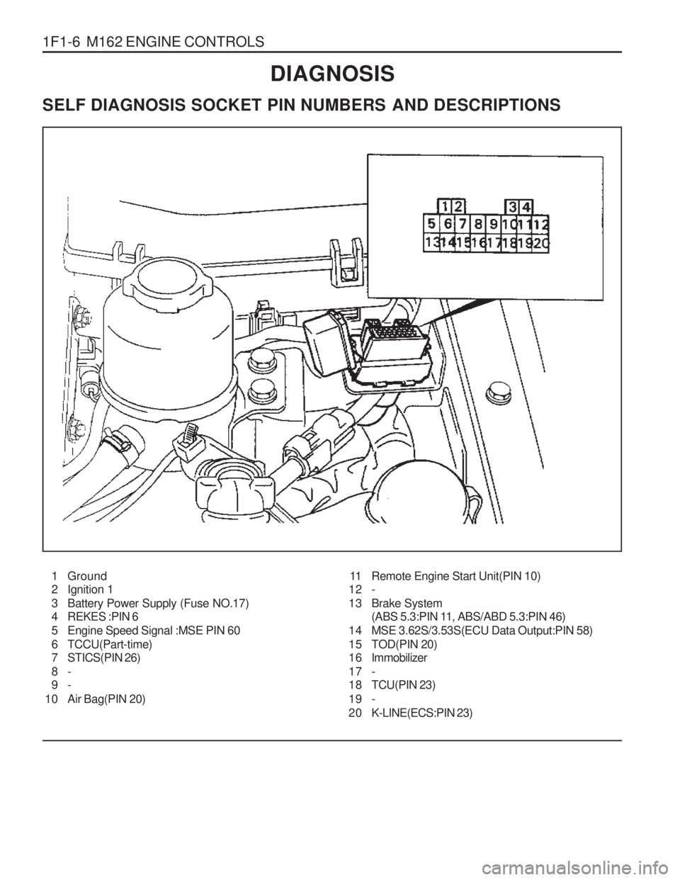
1F1-6 M162 ENGINE CONTROLSDIAGNOSIS
SELF DIAGNOSIS SOCKET PIN NUMBERS AND DESCRIPTIONS
1 Ground
2 Ignition 1
3 Battery Power Supply (Fuse NO.17)
4 REKES :PIN 6
5 Engine Speed Signal :MSE PIN 60
6 TCCU(Part-time)
7 STICS(PIN 26) 8- 9-
10 Air Bag(PIN 20) 11 Remote Engine Start Unit(PIN 10)
12 -
13 Brake System (ABS 5.3:PIN 11, ABS/ABD 5.3:PIN 46)
14 MSE 3.62S/3.53S(ECU Data Output:PIN 58)
15 TOD(PIN 20)
1 6 Immobilizer
17 -
18 TCU(PIN 23)
19 -
2 0 K-LINE(ECS:PIN 23)
Page 553 of 1574
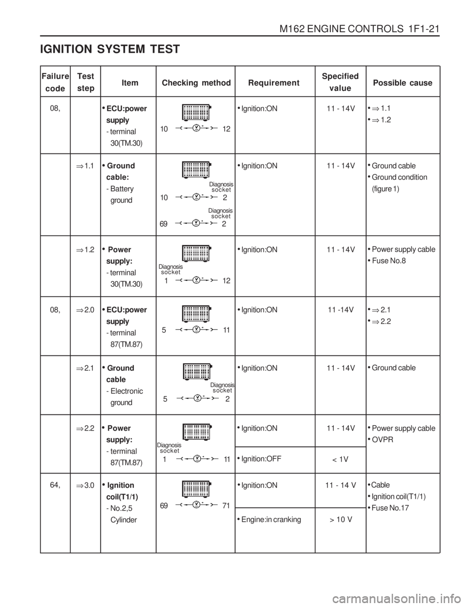
M162 ENGINE CONTROLS 1F1-21
Failurecode ItemChecking method
Ignition:ON
Test stepRequirementSpecified
value Possible cause
10 12 11 - 14V
ECU:power
supply - terminal 30(TM.30)
� 2.2
Power
supply:
- terminal 87(TM.87)
Ignition:ON
Power supply cable
OVPR
IGNITION SYSTEM TEST
08,
� 1.1
� 1.2
� 1.1
Ignition:ON
10 2 11 - 14V
Ground
cable:- Battery ground
Ground cable
Ground condition
(figure 1)
Diagnosis
socket
69 2
Diagnosis socket
� 1.2
Ignition:ON
11 2 11 - 14V
Power
supply: - terminal 30(TM.30)
Power supply cable
Fuse No.8
Diagnosis socket
� 2.0
Ignition:ON
51 1 11 -14V
ECU:power
supply - terminal 87(TM.87)
08,
� 2.1
� 2.2
� 2.1
Ignition:ON 11 - 14V
Ground
cable - Electronic ground
Ground cable
52
Diagnosis socket
11 1
Diagnosis
socket
Ignition:OFF
11 - 14V
< 1V
� 3.0
Ignition:ON
69 71 11 - 14 V
Ignition
coil(T1/1) - No.2,5 Cylinder64,
Cable
Ignition coil(T1/1)
Fuse No.17
Engine:in cranking > 10 V
Page 554 of 1574
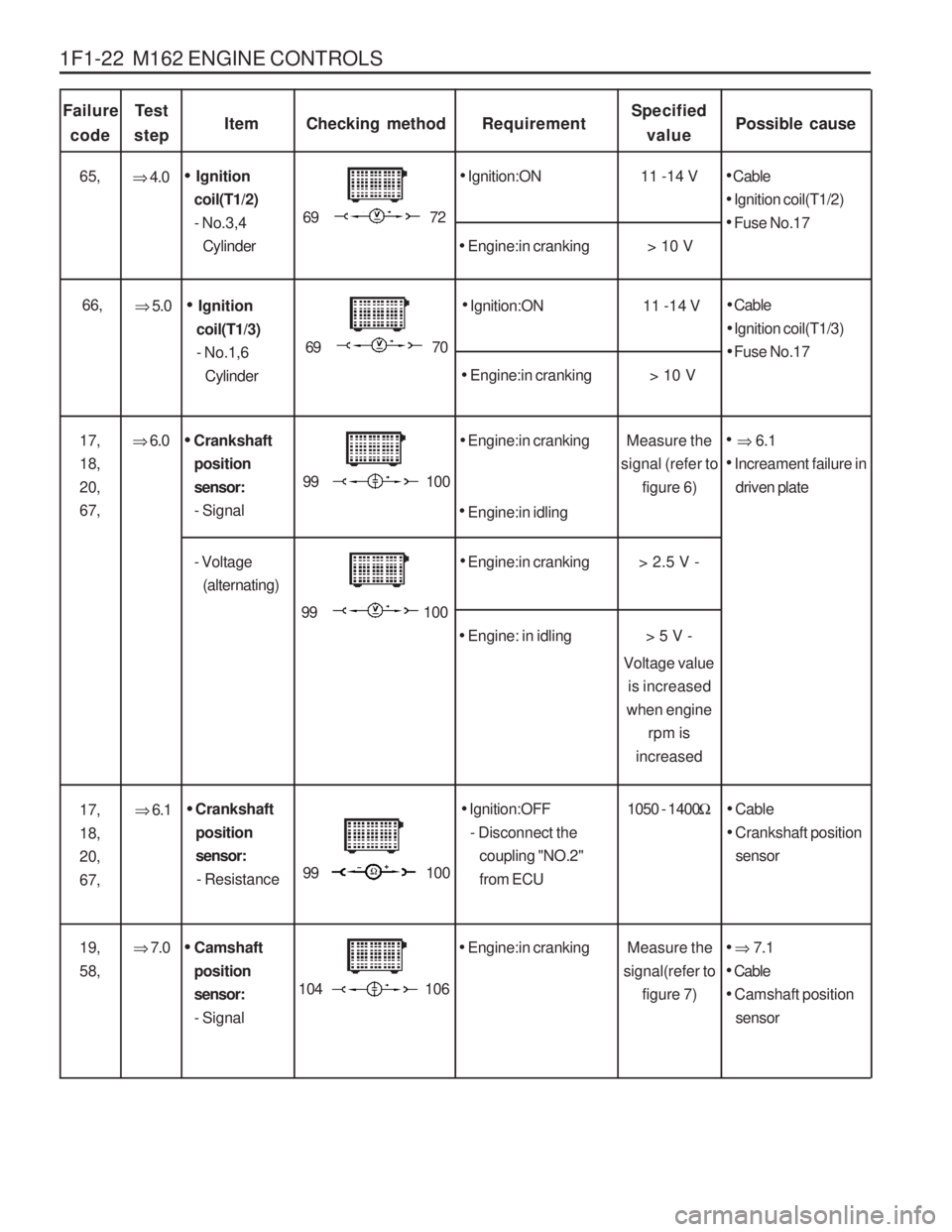
1F1-22 M162 ENGINE CONTROLS
Failurecode ItemChecking method
Te s t
stepRequirementSpecified value Possible cause
�
6.1
Crankshaft
position sensor:- Resistance
Ignition:OFF
- Disconnect the coupling "NO.2"from ECU
Cable
Crankshaft position
sensor
�
6.0
Engine:in cranking
99 100 Measure the
signal (refer to figure 6)
Crankshaft
positionsensor:- Signal
17, 18,20,67,
� 6.1
Increament failure in
driven plate
> 5 V -
99 100
99 100
1050 - 1400
�
� 7.0
Engine:in cranking
104 106
� 7.1
Cable
Camshaft position
sensor
Measure the
signal(refer to figure 7)
Camshaft
position sensor:- Signal
� 4.0
Ignition:ON
69 72 11 -14 V
Ignition
coil(T1/2) - No.3,4 Cylinder65,
Cable
Ignition coil(T1/2)
Fuse No.17
Engine:in cranking > 10 V
Engine:in idling
- Voltage (alternating)
Engine:in cranking
Engine: in idling > 2.5 V -
19, 58,
�
5.0
Ignition:ON
69 70 11 -14 V
Ignition
coil(T1/3) - No.1,6 Cylinder66,
Cable
Ignition coil(T1/3)
Fuse No.17
Engine:in cranking > 10 V
17, 18,20,67, Voltage value
is increased
when engine rpm is
increased
Page 564 of 1574
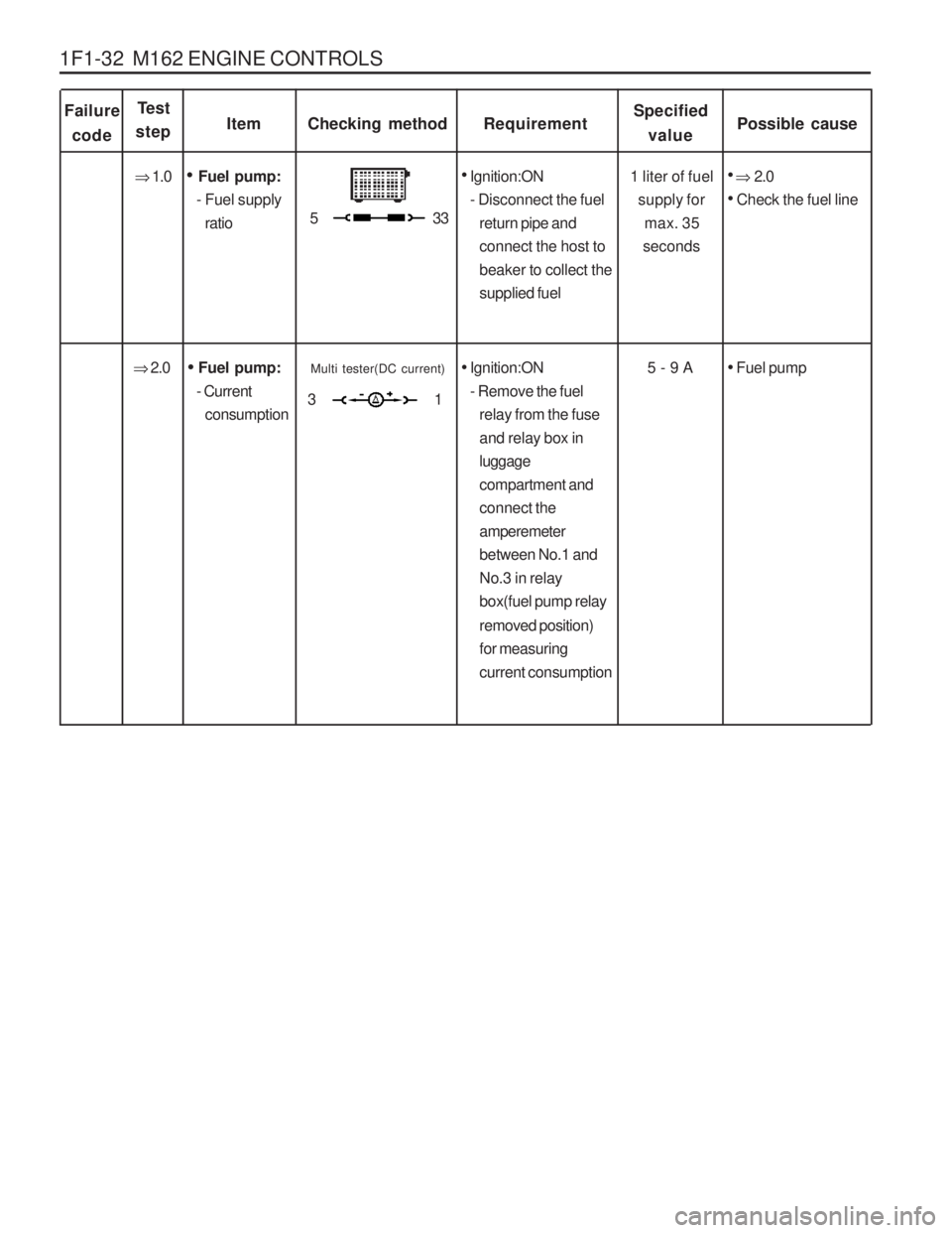
1F1-32 M162 ENGINE CONTROLS
Failurecode ItemChecking method
Test
stepRequirementSpecified
value Possible cause
1 liter of fuel supply formax. 35
seconds
Fuel pump:
- Fuel supply ratio
Ignition:ON
- Disconnect the fuel return pipe and connect the host tobeaker to collect thesupplied fuel
�
1.0
� 2.0
Check the fuel line
5 - 9 A
Fuel pump:
- Current consumption
Ignition:ON
- Remove the fuel relay from the fuseand relay box inluggagecompartment andconnect theamperemeterbetween No.1 andNo.3 in relaybox(fuel pump relay removed position) for measuringcurrent consumption
�
2.0
Fuel pump
53 3
Multi tester(DC current)
31
Page 593 of 1574
M162 ENGINE CONTROLS 1F1-61
Notice Replace the fuel pump relay if the measured value is over 9A.
Notice Check the fuel filter and fuel line when the fuel delivery is not within specified value.
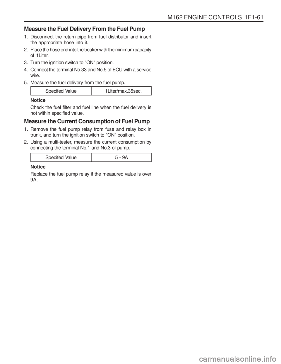
Measure the Current Consumption of Fuel Pump
1. Remove the fuel pump relay from fuse and relay box in trunk, and turn the ignition switch to "ON" position.
2. Using a multi-tester, measure the current consumption by connecting the terminal No.1 and No.3 of pump.
Measure the Fuel Delivery From the Fuel Pump
1. Disconnect the return pipe from fuel distributor and insert
the appropriate hose into it.
2 . Place the hose end into the beaker with the minimum capacity of 1Liter.
3. Turn the ignition switch to "ON" position.
4. Connect the terminal No.33 and No.5 of ECU with a service wire.
5. Measure the fuel delivery from the fuel pump.
1Liter/max.35sec.
Specifed Value
5 - 9A
Specifed Value
Page 846 of 1574
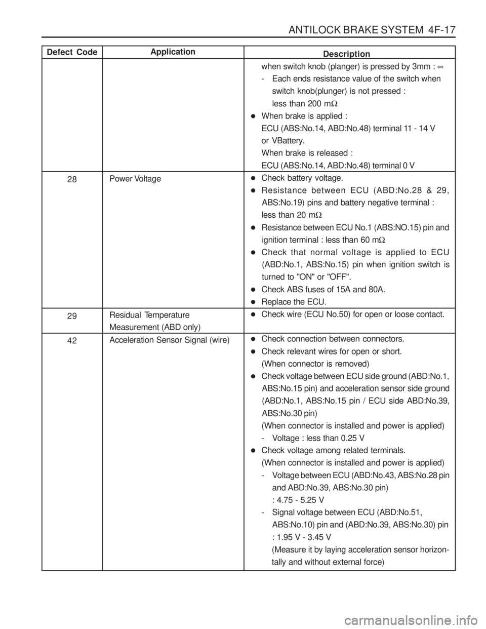
ANTILOCK BRAKE SYSTEM 4F-17
Application
Power Voltage
Residual Temperature Measurement (ABD only) Acceleration Sensor Signal (wire)Defect Code
28 29 42Description
when switch knob (planger) is pressed by 3mm : �
- Each ends resistance value of the switch when switch knob(plunger) is not pressed : less than 200 m �
� When brake is applied :
ECU (ABS:No.14, ABD:No.48) terminal 11 - 14 V
or VBattery.When brake is released : ECU (ABS:No.14, ABD:No.48) terminal 0 V
� Check battery voltage.
� Resistance between ECU (ABD:No.28 & 29,
ABS:No.19) pins and battery negative terminal :
less than 20 m �
� Resistance between ECU No.1 (ABS:NO.15) pin and
ignition terminal : less than 60 m �
� Check that normal voltage is applied to ECU
(ABD:No.1, ABS:No.15) pin when ignition switch is turned to "ON" or "OFF".
� Check ABS fuses of 15A and 80A.
� Replace the ECU.
� Check wire (ECU No.50) for open or loose contact.
� Check connection between connectors.
� Check relevant wires for open or short.(When connector is removed)
� Check voltage between ECU side ground (ABD:No.1,
ABS:No.15 pin) and acceleration sensor side ground(ABD:No.1, ABS:No.15 pin / ECU side ABD:No.39, ABS:No.30 pin)
(When connector is installed and power is applied)
- Voltage : less than 0.25 V
� Check voltage among related terminals.(When connector is installed and power is applied)
- Voltage between ECU (ABD:No.43, ABS:No.28 pin
and ABD:No.39, ABS:No.30 pin) : 4.75 - 5.25 V
- Signal voltage between ECU (ABD:No.51, ABS:No.10) pin and (ABD:No.39, ABS:No.30) pin : 1.95 V - 3.45 V
(Measure it by laying acceleration sensor horizon- tally and without external force)
Page 1096 of 1574
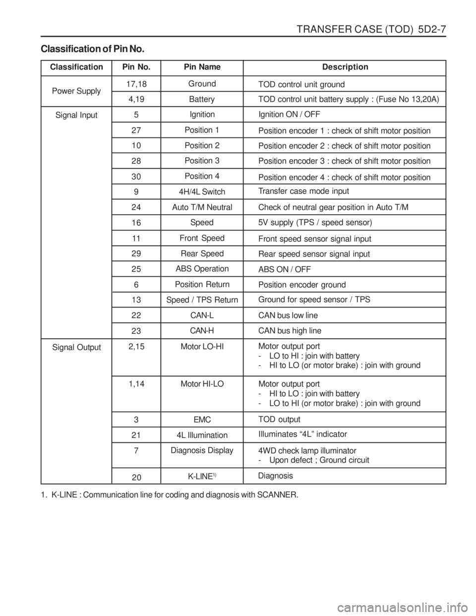
TRANSFER CASE (TOD) 5D2-7
1. K-LINE : Communication line for coding and diagnosis with SCANNER.
Classification of Pin No.
Classification
Pin No. Pin Name Description
Power Supply 17,18
Ground
TOD control unit ground
4,19 Battery TOD control unit battery supply : (Fuse No 13,20A)
5 Ignition Ignition ON / OFF
27 Position 1
Position encoder 1 : check of shift motor position
10 Position 2 Position encoder 2 : check of shift motor position
28 Position 3
Position encoder 3 : check of shift motor position
30 Position 4
Position encoder 4 : check of shift motor position
9 4H/4L Switch Transfer case mode input
24 Auto T/M Neutral Check of neutral gear position in Auto T/M 16 Speed 5V supply (TPS / speed sensor)
11 Front Speed
Front speed sensor signal input
Signal Input
29 Rear Speed Rear speed sensor signal input
25 ABS Operation
ABS ON / OFF
6 Position Return
Position encoder ground
13 Speed / TPS Return Ground for speed sensor / TPS
2 2 CAN-L CAN bus low line
23 CAN-H
CAN bus high line
2,15 Motor LO-HI Motor output port
- LO to HI : join with battery
- HI to LO (or motor brake) : join with ground
1,14 Motor HI-LO Motor output port
- HI to LO : join with battery
- LO to HI (or motor brake) : join with ground
3 EMC TOD output
Signal Output
21 4L Illumination Illuminates
“4L ” indicator
7 Diagnosis Display
4WD check lamp illuminator
- Upon defect ; Ground circuit
20K-LINE1)
Diagnosis