engine SSANGYONG NEW ACTYON SPORTS 2013 Service Manual
[x] Cancel search | Manufacturer: SSANGYONG, Model Year: 2013, Model line: NEW ACTYON SPORTS, Model: SSANGYONG NEW ACTYON SPORTS 2013Pages: 751, PDF Size: 72.63 MB
Page 261 of 751
01-12
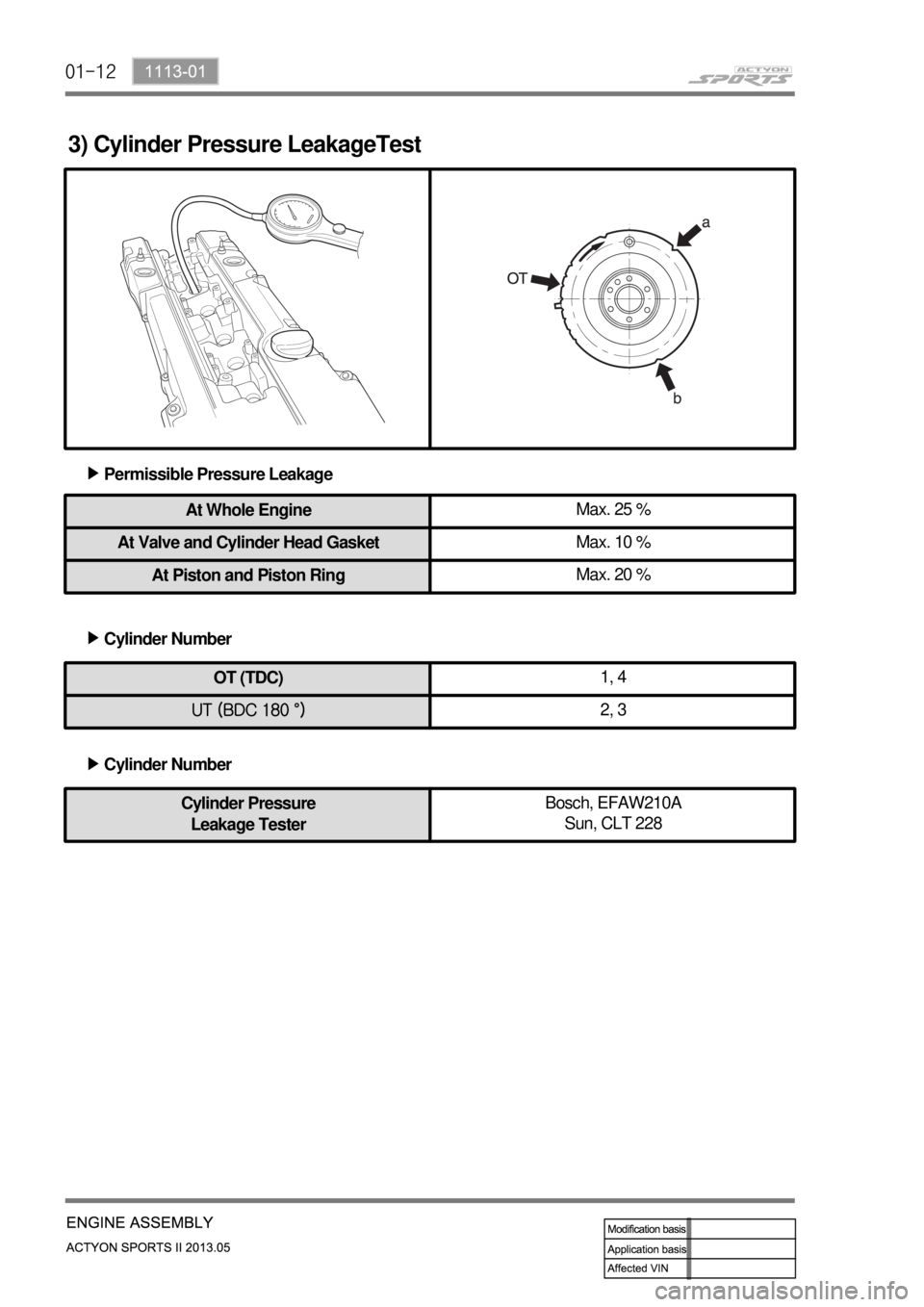
3) Cylinder Pressure LeakageTest
Permissible Pressure Leakage ▶
At Whole EngineMax. 25 %
At Valve and Cylinder Head GasketMax. 10 %
At Piston and Piston RingMax. 20 %
OT (TDC)1, 4
UT (BDC 180 °)2, 3
Cylinder Number ▶
Cylinder Number ▶
Cylinder Pressure
Leakage TesterBosch, EFAW210A
Sun, CLT 228
Page 262 of 751
01-131113-01
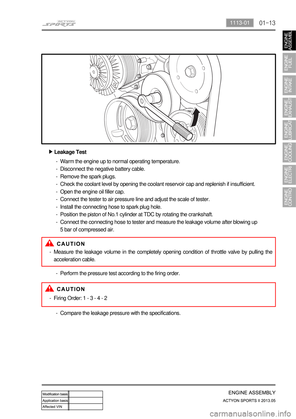
Leakage Test ▶
Warm the engine up to normal operating temperature.
Disconnect the negative battery cable.
Remove the spark plugs.
Check the coolant level by opening the coolant reservoir cap and replenish if insufficient.
Open the engine oil filler cap.
Connect the tester to air pressure line and adjust the scale of tester.
Install the connecting hose to spark plug hole.
Position the piston of No.1 cylinder at TDC by rotating the crankshaft.
Connect the connecting hose to tester and measure the leakage volume after blowing up
5 bar of compressed air. -
-
-
-
-
-
-
-
-
Measure the leakage volume in the completely opening condition of throttle valve by pulling the
acceleration cable. -
Perform the pressure test according to the firing order. -
Firing Order: 1 - 3 - 4 - 2 -
Compare the leakage pressure with the specifications. -
Page 268 of 751
01-191113-01
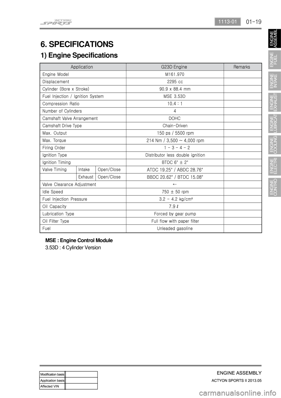
6. SPECIFICATIONS
1) Engine Specifications
MSE : Engine Control Module
3.53D : 4 Cylinder Version
Page 272 of 751
02-32211-06
1. FUEL SYSTEM SPECIFICATION
Use Only Unleaded Fuel Rated at 89 Octane or Higher ▶
Fuel quality and additives contained in fuel have a significant effect on power output, drivability, and
life of the engine.
Fuel with too low an octane number can cause engine knock.
Caution: Use of fuel with an octane number lower than 89 may damage engine and exhaust
system.
To prevent accidental use of leaded fuel, the nozzles for leaded fuel are larger, and will not fit the
fuel filler neck of your vehicle. -
Do Not Use Methanol ▶
Fuels containing methanol (wood alcohol) should not be used in vehicle.
This type of fuel can reduce vehicle performance and damage components of the fuel system.
Use of methanol may damage the fuel system. -
Vehicle Fueling from Drums or Storage Containers ▶
For safety reasons (particularly when using noncommercial fueling systems) fuel containers, pumps
and hoses must be properly earthed.
Static electricity build up can occur under certain atmospheric and fuel flow conditions if unearthed
hoses, particularly plastic, are fitted to the fuel-dispensing pump.
It is therefore recommended that earthed pumps with integrally earthed hoses be used, and that
storage containers be properly earthed during all noncommercial fueling operations.
Page 274 of 751
02-52211-06
1. FUEL SYSTEM
The function of the fuel metering system is to deliver the correct amount of fuel to the engine under all
operating conditions.
The fuel is delivered to the engine by the individual fuel injectors mounted into the intake manifold nea
r
each cylinder.
The main fuel control sensors are the Mass Air Flow (MAF) sensor and the oxygen (O2) sensors.
The MAF sensor monitors the mass flow of the air being drawn into the engine. An electrically heated
element is mounted in the intake air stream, where it is cooled by the flow of incoming air. Engine Control
Module (ECM) modulates the flow of heating current to maintain the temperature differential between the
heated film and the intake air at a constant level. The amount of heating current required to maintain the
temperature thus provides an index for the mass air flow. This
concept automatically compensates for variations in air density, as this is one of the factors that
determines the amount of warmth that the surrounding air absorbs from the heated element. MAF
sensor is located between the air filter and the throttle valve.
Under high fuel demands, the MAF sensor reads a high mass flow condition, such as wide open throttle.
The ECM uses this information to enrich the mixture, thus increasing the fuel injector on-time, to provide
the correct amount of fuel. When decelerating, the mass flow decreases. This mass flow change is
sensed by the MAF sensor and read by the ECM, which then decreases the fuel injector on-time due to
the low fuel demand conditions.
The O2 sensors are located in the exhaust pipe before catalytic converter. The O2 sensors indicate to
the ECM the amount of oxygen in the exhaust gas, and the ECM changes the air/fuel ratio to the engine
by controlling the fuel injectors. The best air/fuel ratio to minimize exhaust emissions is 14.7 to 1, which
allows the catalytic converter to operate most efficiently. Because
of the constant measuring and adjusting of the air/fuel ratio, the fuel injection system is called a "closed
loop" system.
The ECM uses voltage inputs from several sensors to determine how much fuel to provide to the engine.
The fuel is delivered under one of several conditions, called "modes".
Page 275 of 751
02-6
1) Starting Mode
When the ignition is turned ON, the ECM turns the fuel pump relay on for 1 second. The fuel pump then
builds fuel pressure. The ECM also checks the Engine Coolant Temperature (ECT) sensor and the
Throttle Position (TP) sensor and determines the proper air/fuel ratio for starting the engine. This ranges
from1.5 to 1 at -36 °C (-33 °F) coolant temperature to 14.7 to 1 at 94 °C (201 °F) coolant
temperature. The ECM controls the amountof fuel delivered in the starting mode by changing how long
the fuel injector is turned on and off. This is done by ''pulsing" the fuel injectors for very short times.
2) Run Mode
The run mode has two conditions called ''open loop" and ''closed loop".
3) Open Loop
When the engine is first started and it is above 690 rpm, the system goes into "open loop" operation. In
"open loop", the ECM ignores the signal from the HO2S and calculates the air/fuel ratio based on inputs
from the ECT sensor and the MAF sensor. The ECM stays in "open loop" until the following conditions
are met:
The O2 has a varying voltage output, showing that it is hot enough to operate properly.
The ECT sensor is above a specified temperature (22.5 °C).
A specific amount of time has elapsed after starting the engine. -
-
-
4) Closed Loop
The specific values for the above conditions vary with different engines and are stored in the
Electronically Erasable Programmable Read-Only Memory (EEPROM).
When these conditions are met, the system goes into "closed loop" operation. In "closed loop", the ECM
calculates the air/fuel ratio (fuel injector on- time) based on the signals from the O2 sensors. This allows
the air/fuel ratio to stay very close to 14.7 to 1.
5) Acceleration Mode
The ECM responds to rapid changes in throttle position and airflow and provides extra fuel.
6) Deceleration Mode
The ECM responds to changes in throttle position and airflow and reduces the amount of fuel. When
deceleration is very fast, the ECM can cut off fuel completely for short periods of time.
Page 276 of 751
02-72211-06
7) Battery Voltage Correction Mode
When battery voltage is low, the ECM can compensate for a weak spark delivered by the ignition
module by using the following methods:
Increasing the fuel injector pulse width.
Increasing the idle speed rpm.
Increasing the ignition dwell time. -
-
-
8) Fuel Cut-Off Mode
No fuel is delivered by the fuel injectors when the ignition is off. This prevents dieseling or engine runon.
Also, the fuel is not delivered if there are no reference pulses received from the CKP sensor. This
prevents flooding.
Page 279 of 751
04-4
1. DESCRIPTION AND OPERATION
1) Exhaust System
When you are inspecting or replacing exhaust system components, make sure there is adequate
clearance from all points on the underbody to avoid possible
overheating of the floor panel and possible damage to the passenger compartment insulation and trim
materials.
Check the complete exhaust system and the nearby body areas and trunk lid for broken, damaged,
missing or mispositioned parts, open seams, holes, loose connections, or other deterioration which
could permit exhaust fumes to seep into the trunk may be an indication of a problem in one of these
areas. Any defects should be corrected immediately.
2) Catalytic Converter (Gasoline Engine)
When jacking or lifting the vehicle from the body side rails, be certain that the lift pads do not contact
the catalytic converter, as this could damage the catalytic converter.
Use of anything other than unleaded fuel will damage the catalyst in the catalytic converter. 1.
2.
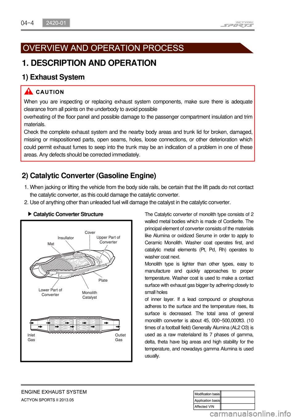
Catalytic Converter Structure ▶
The Catalytic converter of monolith type consists of 2
walled metal bodies which is made of Cordierite. The
principal element of converter consists of the materials
like Alumina or oxidized Serume in order to apply to
Ceramic Monolith. Washer coat operates first, and
catalytic metal elements (Pt, Pd, Rh) operates to
washer coat next.
Monolith type is lighter than other types, easy to
manufacture and quickly approaches to prope
r
temperature. Washer coat is used to make a contact
surface with exhaust gas bigger by adhering closely to
small holes
of inner layer. If a lead compound or phosphorus
adheres to the surface and the temperature rises, its
surface is decreased. The total area of general
monolith converter is about 45, 000~500,000ft3. (10
times of a football field) Generally Alumina (AL2 O3) is
used as a raw materialand its 7 phases of gamma,
delta, theta have big areas and high stability for the
temperature, and nowadays gamma Alumina is used
usually.
Page 281 of 751
04-6
Method for Reduction of NOx ▶
NOx is generated a great deal in case that combustion temperature and excess air factor are high. EGR
valve can decrease NOx (30 to 35% decrease) by making temperature of combustion chamber fall by
means of exhaust gas re-circulation.
EGR valve is installed on the diesel engine of Musso, Korando, Istana and Rexton.
And micro switch is installed together to control EGR valve.
The setting method of micro switch is identical with the existing one. -
-
Page 283 of 751
06-32110-01
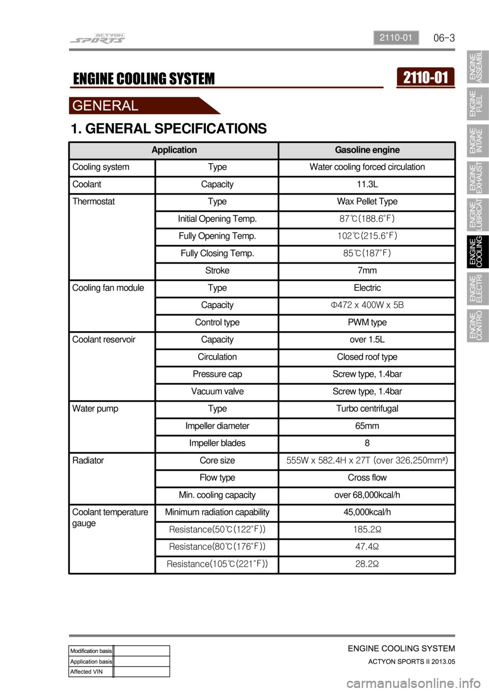
1. GENERAL SPECIFICATIONS
Application Gasoline engine
Cooling system Type Water cooling forced circulation
Coolant Capacity 11.3L
Thermostat Type Wax Pellet Type
Initial Opening Temp.87℃(188.6℉)
Fully Opening Temp.102℃(215.6℉)
Fully Closing Temp.85℃(187℉)
Stroke 7mm
Cooling fan module Type Electric
CapacityΦ472 x 400W x 5B
Control type PWM type
Coolant reservoir Capacity over 1.5L
Circulation Closed roof type
Pressure cap Screw type, 1.4bar
Vacuum valve Screw type, 1.4bar
Water pump Type Turbo centrifugal
Impeller diameter 65mm
Impeller blades 8
Radiator Core size555W x 582.4H x 27T (over 326,250mm²)
Flow type Cross flow
Min. cooling capacity over 68,000kcal/h
Coolant temperature
gaugeMinimum radiation capability 45,000kcal/h
Resistance(50℃(122℉)) 185.2Ω
Resistance(80℃(176℉)) 47.4Ω
Resistance(105℃(221℉)) 28.2Ω