tow SSANGYONG NEW ACTYON SPORTS 2013 User Guide
[x] Cancel search | Manufacturer: SSANGYONG, Model Year: 2013, Model line: NEW ACTYON SPORTS, Model: SSANGYONG NEW ACTYON SPORTS 2013Pages: 751, PDF Size: 72.63 MB
Page 618 of 751
11-16
2) Operation of ESP System
The ESP (Electronic Stability Program) has been developed to help a driver avoid danger of losing
control of the vehicle stability due to understeer or oversteer during cornering. The yaw rate sensor,
lateral sensor and longitudinal sensor in the sensor cluster and the steering wheel angle sensor under
the steering column detect the vehicle conditions when the inner or outer wheels are spinning during
oversteer, understeer or cornering. The ESP ECU controls against oversteer or understeer during
cornering by controlling the vehicle stability using input values from these sensors and applying the
braking force to the corresponding wheels independently. The system also controls the engine power
right before the wheel spin synchronized with the ASR function to decelerate the vehicle automatically in
order to maintain the vehicle stable during cornering.
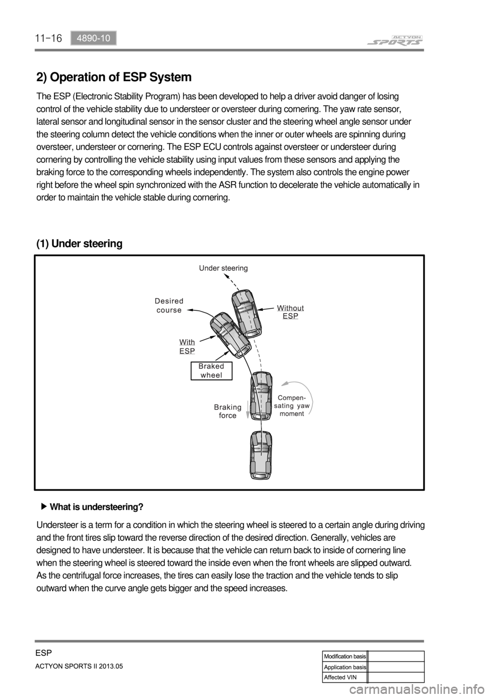
(1) Under steering
What is understeering? ▶
Understeer is a term for a condition in which the steering wheel is steered to a certain angle during driving
and the front tires slip toward the reverse direction of the desired direction. Generally, vehicles are
designed to have understeer. It is because that the vehicle can return back to inside of cornering line
when the steering wheel is steered toward the inside even when the front wheels are slipped outward.
As the centrifugal force increases, the tires can easily lose the traction and the vehicle tends to slip
outward when the curve angle gets bigger and the speed increases.
Page 619 of 751
11-174890-10
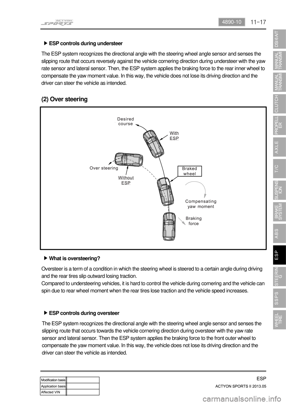
ESP controls during understeer ▶
The ESP system recognizes the directional angle with the steering wheel angle sensor and senses the
slipping route that occurs reversely against the vehicle cornering direction during understeer with the ya
w
rate sensor and lateral sensor. Then, the ESP system applies the braking force to the rear inner wheel to
compensate the yaw moment value. In this way, the vehicle does not lose its driving direction and the
driver can steer the vehicle as intended.
(2) Over steering
What is oversteering? ▶
Oversteer is a term of a condition in which the steering wheel is steered to a certain angle during driving
and the rear tires slip outward losing traction.
Compared to understeering vehicles, it is hard to control the vehicle during cornering and the vehicle can
spin due to rear wheel moment when the rear tires lose traction and the vehicle speed increases.
ESP controls during oversteer ▶
The ESP system recognizes the directional angle with the steering wheel angle sensor and senses the
slipping route that occurs towards the vehicle cornering direction during oversteer with the yaw rate
sensor and lateral sensor. Then the ESP system applies the braking force to the front outer wheel to
compensate the yaw moment value. In this way, the vehicle does not lose its driving direction and the
driver can steer the vehicle as intended.
Page 660 of 751

13-10
▶ In medium and high speed driving
The shaft operation force of solenoid rod is reduced due to the reduction of output current from SSPS
control unit.
The coil spring pulls the PCV spool toward solenoid valve to open it.
The hydraulic pressure from pump flows to pinion reaction area through orifice and applies reaction
force to reaction plunger.
At this time, the reaction plunger transmits the reaction force to V-groove in input shaft to provide heavy
steerability. 1.
2.
3.
4.
Page 667 of 751
14-6
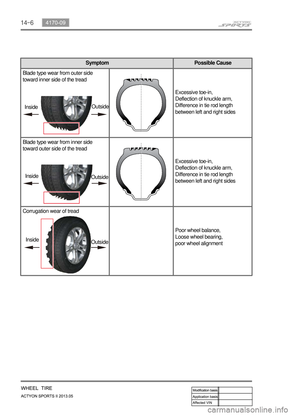
Symptom Possible Cause
Blade type wear from outer side
toward inner side of the tread
Excessive toe-in,
Deflection of knuckle arm,
Difference in tie rod length
between left and right sides
Blade type wear from inner side
toward outer side of the tread
Excessive toe-in,
Deflection of knuckle arm,
Difference in tie rod length
between left and right sides
Corrugation wear of tread
Poor wheel balance,
Loose wheel bearing,
poor wheel alignment
InsideOutside
Inside
Outside
Inside
Outside
Page 679 of 751
14-18
4. WHEEL ALIGNMENT
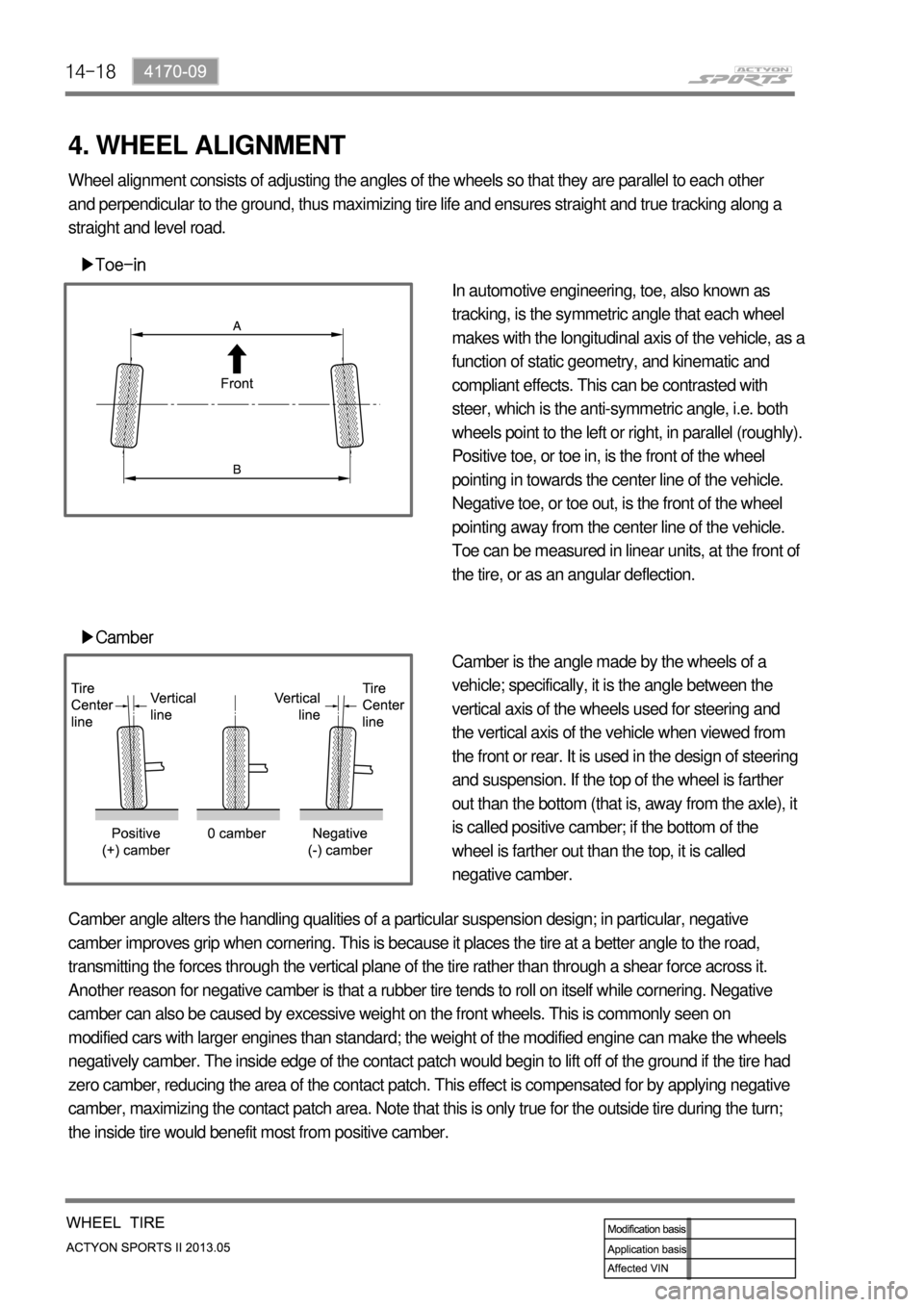
▶Toe-in
▶Camber
In automotive engineering, toe, also known as
tracking, is the symmetric angle that each wheel
makes with the longitudinal axis of the vehicle, as a
function of static geometry, and kinematic and
compliant effects. This can be contrasted with
steer, which is the anti-symmetric angle, i.e. both
wheels point to the left or right, in parallel (roughly).
Positive toe, or toe in, is the front of the wheel
pointing in towards the center line of the vehicle.
Negative toe, or toe out, is the front of the wheel
pointing away from the center line of the vehicle.
Toe can be measured in linear units, at the front of
the tire, or as an angular deflection.
Camber is the angle made by the wheels of a
vehicle; specifically, it is the angle between the
vertical axis of the wheels used for steering and
the vertical axis of the vehicle when viewed from
the front or rear. It is used in the design of steering
and suspension. If the top of the wheel is farther
out than the bottom (that is, away from the axle), it
is called positive camber; if the bottom of the
wheel is farther out than the top, it is called
negative camber. Wheel alignment consists of adjusting the angles of the wheels so that they are parallel to each other
and perpendicular to the ground, thus maximizing tire life and ensures straight and true tracking along a
straight and level road.
Camber angle alters the handling qualities of a particular suspension design; in particular, negative
camber improves grip when cornering. This is because it places the tire at a better angle to the road,
transmitting the forces through the vertical plane of the tire rather than through a shear force across it.
Another reason for negative camber is that a rubber tire tends to roll on itself while cornering. Negative
camber can also be caused by excessive weight on the front wheels. This is commonly seen on
modified cars with larger engines than standard; the weight of the modified engine can make the wheels
negatively camber. The inside edge of the contact patch would begin to lift off of the ground if the tire had
zero camber, reducing the area of the contact patch. This effect is compensated for by applying negative
camber, maximizing the contact patch area. Note that this is only true for the outside tire during the turn;
the inside tire would benefit most from positive camber.
Page 688 of 751
01-96810-01
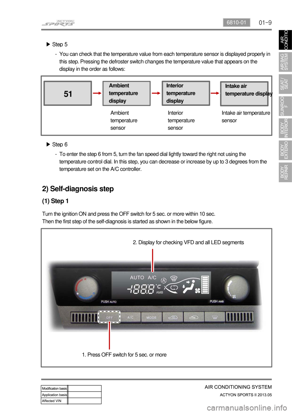
▶ Step 5
Ambient
temperature
display
51
Interior
temperature
displayIntake air
temperature display
Ambient
temperature
sensorInterior
temperature
sensorIntake air temperature
sensor
▶ Step 6
To enter the step 6 from 5, turn the fan speed dial lightly toward the right not using the
temperature control dial. In this step, you can decrease or increase by up to 3 degrees from the
temperature set on the A/C controller. -You can check that the temperature value from each temperature sensor is displayed properly in
this step. Pressing the defroster switch changes the temperature value that appears on the
display in the order as follows: -
2) Self-diagnosis step
(1) Step 1
Turn the ignition ON and press the OFF switch for 5 sec. or more within 10 sec.
Then the first step of the self-diagnosis is started as shown in the below figure.
2. Display for checking VFD and all LED segments
1. Press OFF switch for 5 sec. or more
Page 689 of 751

01-10
(2) Step 2
The sensors and air mix door are checked for proper operation in this step. When the step 2 is started,
the number "2", which indicates that the system is in the step 2, apprears on the display and the check
for sensors is performed. Once the check is done (for 10 to 20 sec.), the one digit number between 0
and 8 is added behind "2". "20" means there is no fault code. For the meaning of the rest of the
numbers, refer to the description below.
1. Turn temperature dial lightly toward right to enter step 2
10 to 20
sec.
System starts sensor
check after "2" is displayed 2.
Fault code for sensor
appears and blinks 3.
Fault code no. 1
(ambient temperature
sensor) blinks twiceFault code no. 5 (sun
sensor) blinks twice
(fault codes appears
sequentially)
If "-" is displayed before "2", it means that
the sensor for that flashing fault code has
a short circuit.
Ambient temperature
sensor short circuited
Refer to the following table for the meaning of the fault code.
Page 690 of 751

01-116810-01
(3) Step 3
In this step, you can check the position and condition of the air source door and mode door. To start step
3, turn the temperature control dial lightly toward the right and confirm that the number 3 appears on the
display. It takes several tens of seconds to finish the check. If there is no fault code, "30" is displayed.
And if there is a malfunction, the corresponding fault code is added as described in the step 2.
Turn temperature dial lightly toward
right to enter step 3 1.
System starts sensor
check after "3" is
displayed 2. Fault code for
sensor appears and
blinks (30 is
displayed when
there is no fault) 3.
Refer to the following table for the meaning of the fault code.
Page 691 of 751

01-12
In this step, the door position of each actuator, fan speed and operation of the compressor are checked.
To enter this step, turn the temperature dial to the right in the step 3. The number, "41", appears on the
display as soon as the step 4 is started. Press the defroster switch to change the diagnosis mode.
(4) Step 4
Press
Press
Press
PressPress
Press
Turn temperature dial lightly
toward right to enter step 4 1.
Below table describes the detailed diagnosis items performed for each number. Check the
corresponding component for proper operation according to the table. The voltage values listed in the
table are the output voltage to operate the blower motor. The higher the voltage, the faster the fan speed
is.
Page 692 of 751
01-136810-01
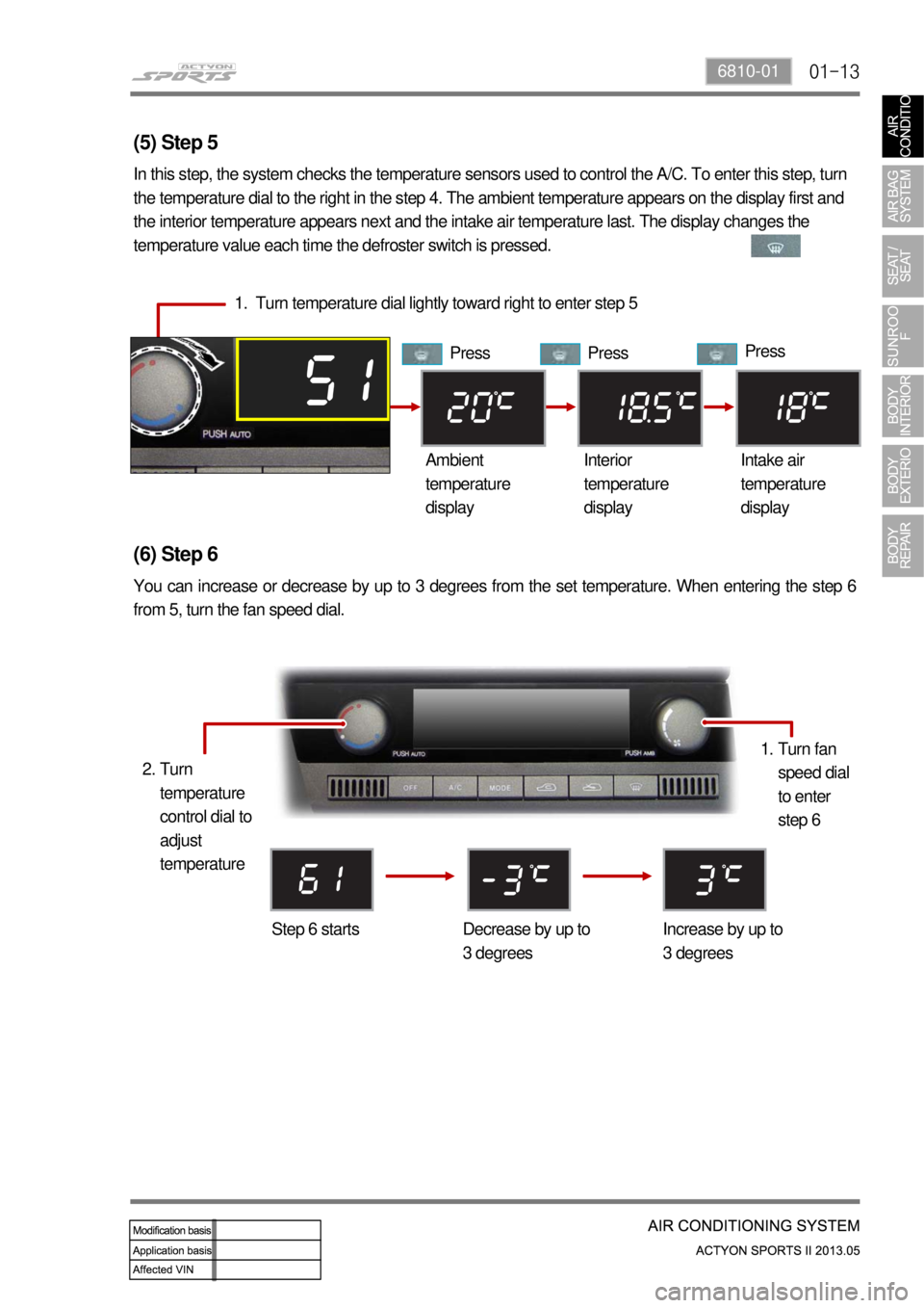
(5) Step 5
In this step, the system checks the temperature sensors used to control the A/C. To enter this step, turn
the temperature dial to the right in the step 4. The ambient temperature appears on the display first and
the interior temperature appears next and the intake air temperature last. The display changes the
temperature value each time the defroster switch is pressed.
1. Turn temperature dial lightly toward right to enter step 5
Press Press Press
Ambient
temperature
displayInterior
temperature
displayIntake air
temperature
display
(6) Step 6
You can increase or decrease by up to 3 degrees from the set temperature. When entering the step 6
from 5, turn the fan speed dial.
Step 6 starts Decrease by up to
3 degreesIncrease by up to
3 degreesTurn fan
speed dial
to enter
step 6 1.
Turn
temperature
control dial to
adjust
temperature 2.