engine SSANGYONG NEW ACTYON SPORTS 2013 Service Manual
[x] Cancel search | Manufacturer: SSANGYONG, Model Year: 2013, Model line: NEW ACTYON SPORTS, Model: SSANGYONG NEW ACTYON SPORTS 2013Pages: 751, PDF Size: 72.63 MB
Page 611 of 751
11-94890-10
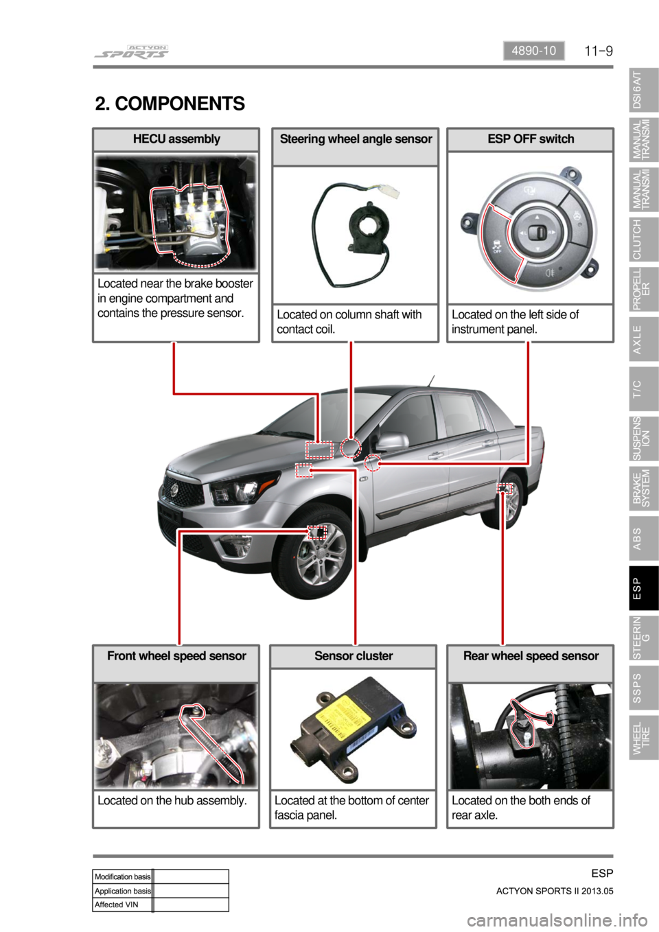
ESP OFF switch
Located on the left side of
instrument panel.
Rear wheel speed sensor
Located on the both ends of
rear axle.Front wheel speed sensor
Located on the hub assembly.Sensor cluster
Located at the bottom of center
fascia panel.
Steering wheel angle sensor
Located on column shaft with
contact coil.HECU assembly
Located near the brake booster
in engine compartment and
contains the pressure sensor.
2. COMPONENTS
Page 612 of 751
11-10
3. FUNCTION
1) Term Definition
ABS: Anti-Lock Brake System ▶
When the brake pedal is abruptly depressed, the HECU calculates the slip ratio of each wheel based on
information received from the wheel speed sensors and controls the hydraulic module data quickly and
precisely in order to maintain the friction between the road surface and tire optimal (static friction).
Therefore, by keeping the friction between the road surface and tire optimal, it is possible to obtain
following effects: Enhanced steering stability, improved direction stability, reduced stopping distance and
etc.
EBD: Electronic brake-Force Distribution ▶
This is to detect the tire speed from the wheel speed sensor in order to supply the braking pressure to
the rear tires individually. In other words, the HECU measures the tire deceleration speed continuously
and controls the rear inlet valve on the hydraulic modulator to obtain optimal braking force as much as
possible. Thereby, stopping distance, braking effect and straight stability are improved.
ESP: Electronic Stability Program ▶
This is used to make the vehicle stabilized to recognize the emergency driving conditions, and to control
the brake for each wheels and the engine power when the brake system or acceleration will not work
any more in dangerous circumstances.
TCS: Traction Control System ▶
When the wheel is slipping due to an excessive engine torque while starting off or driving, this controls
the driving force (braking force + engine torque) in order to prevent the wheel from slipping through the
engine or brake control.
AYC: Active Yaw Control ▶
This has been developed to help a driver avoid danger of losing control of the vehicle stability due to
understeer or oversteer during cornering, which is a part of the ESP function.
HBA: Hydraulic Brake Assistant ▶
Developed based on the fact that elderly drivers depress the brake pedal too soft even when hard
braking is necessary, this an assist system to operate the HECU drive motor immediately and apply high
braking force to the wheels when the brake pedal is depressed softly and the vehicle should be braked
in emergency.
ARP: Active Rollover Protection ▶
This is a supplementary device for safety in ESP system and can help minimize the rollover accidents by
detecting a potential rollover situation through the brake and engine control when making sudden lane
change or turning sharply by adding only the software, without any separate device or switch.
Page 614 of 751
11-12
4. PRECAUTIONS
The warning lamp flashes and warning beep sounds when the ESP is operating
When the ESP operates during vehicle movement, the ESP warning lamp on the instrument panel
flashes and beep comes on every 0.1 second. The ESP system is only a supplementary device for
comfortable driving. When the vehicle exceeds its physical limits, it cannot be controlled.
Do not rely on the system. Keep on the safe driving.
Feeling when ESP is working
When the ESP system activates, the feeling can be different depending on vehicle driving
conditions.
For example, you will feel differently when the ESP system is activated during the ABS is operating
with the brakes applied and when the brakes are not applied on a curve.
If the ESP system operates when the brake is applied, the brake pressure will be increased on the
corresponding wheel which already has braking pressure for the ESP controls.
ARP Operation
During the ARP operation, vehicle safety (rollover prevention) takes the first priority and thus,
stronger engine control is in effect. Consequently, the vehicle speed decreases rapidly, so the driver
must take caution for the vehicle may drift away from the lane.
Noise and vibration that driver feels when ESP system is operating
The ESP system may transfer noise and vibration to the driver due to the pressure changes caused
by the motor and valve operations in a very short period of time. And, keep in mind that the output
and vehicle speed could be decreased without rpm increase due to the ASR function that controls
the engine power.
Page 618 of 751
11-16
2) Operation of ESP System
The ESP (Electronic Stability Program) has been developed to help a driver avoid danger of losing
control of the vehicle stability due to understeer or oversteer during cornering. The yaw rate sensor,
lateral sensor and longitudinal sensor in the sensor cluster and the steering wheel angle sensor under
the steering column detect the vehicle conditions when the inner or outer wheels are spinning during
oversteer, understeer or cornering. The ESP ECU controls against oversteer or understeer during
cornering by controlling the vehicle stability using input values from these sensors and applying the
braking force to the corresponding wheels independently. The system also controls the engine power
right before the wheel spin synchronized with the ASR function to decelerate the vehicle automatically in
order to maintain the vehicle stable during cornering.
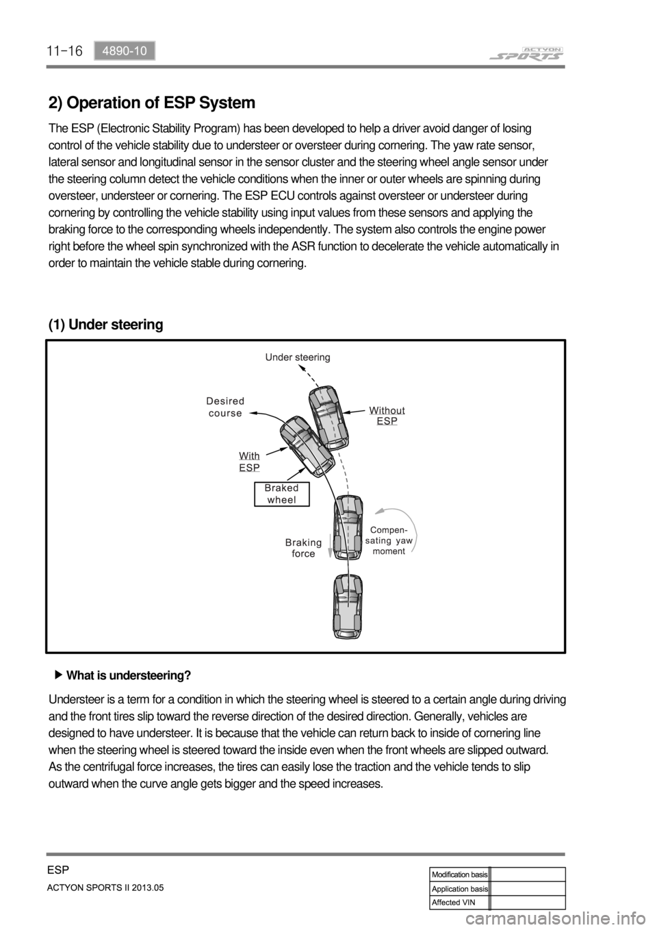
(1) Under steering
What is understeering? ▶
Understeer is a term for a condition in which the steering wheel is steered to a certain angle during driving
and the front tires slip toward the reverse direction of the desired direction. Generally, vehicles are
designed to have understeer. It is because that the vehicle can return back to inside of cornering line
when the steering wheel is steered toward the inside even when the front wheels are slipped outward.
As the centrifugal force increases, the tires can easily lose the traction and the vehicle tends to slip
outward when the curve angle gets bigger and the speed increases.
Page 622 of 751
11-20
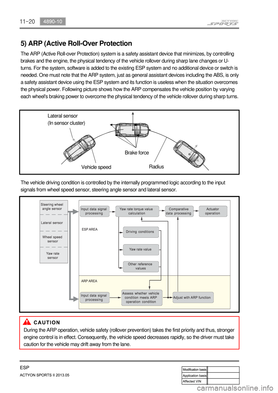
5) ARP (Active Roll-Over Protection
The ARP (Active Roll-over Protection) system is a safety assistant device that minimizes, by controlling
brakes and the engine, the physical tendency of the vehicle rollover during sharp lane changes or U-
turns. For the system, software is added to the existing ESP system and no additional device or switch is
needed. One must note that the ARP system, just as general assistant devices including the ABS, is only
a safety assistant device using the ESP system and its function is useless when the situation overcomes
the physical power. Following picture shows how the ARP compensates the vehicle position by varying
each wheel's braking power to overcome the physical tendency of the vehicle rollover during sharp turns.
Lateral sensor
(In sensor cluster)
Vehicle speedBrake force
Radius
The vehicle driving condition is controlled by the internally programmed logic according to the input
signals from wheel speed sensor, steering angle sensor and lateral sensor.
During the ARP operation, vehicle safety (rollover prevention) takes the first priority and thus, stronger
engine control is in effect. Consequently, the vehicle speed decreases rapidly, so the driver must take
caution for the vehicle may drift away from the lane.
Page 624 of 751
11-22
Circuit description ▶
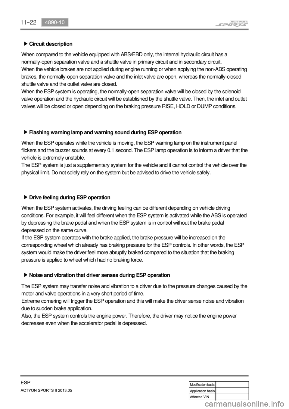
When compared to the vehicle equipped with ABS/EBD only, the internal hydraulic circuit has a
normally-open separation valve and a shuttle valve in primary circuit and in secondary circuit.
When the vehicle brakes are not applied during engine running or when applying the non-ABS operating
brakes, the normally-open separation valve and the inlet valve are open, whereas the normally-closed
shuttle valve and the outlet valve are closed.
When the ESP system is operating, the normally-open separation valve will be closed by the solenoid
valve operation and the hydraulic circuit will be established by the shuttle valve. Then, the inlet and outlet
valves will be closed or open depending on the braking pressure RISE, HOLD or DUMP conditions.
Flashing warning lamp and warning sound during ESP operation ▶
When the ESP operates while the vehicle is moving, the ESP warning lamp on the instrument panel
flickers and the buzzer sounds at every 0.1 second. The ESP lamp operation is to inform a driver that the
vehicle is extremely unstable.
The ESP system is just a supplementary system for the vehicle and it cannot control the vehicle over the
physical limit. Do not solely rely on the system but be advised to drive the vehicle safely.
Drive feeling during ESP operation ▶
When the ESP system activates, the driving feeling can be different depending on vehicle driving
conditions. For example, it will feel different when the ESP system is activated while the ABS is operated
by depressing the brake pedal and when the ESP system is in control without the brake pedal
depressed on the same curve.
If the ESP system operates with the brake applied, the brake pressure will be increased on the
corresponding wheel which already has braking pressure for the ESP controls. In other words, the ESP
system would make the driver feel more abruptly braked compared to the situation that the braking
pressure is applied to wheel which had no braking force.
Noise and vibration that driver senses during ESP operation ▶
The ESP system may transfer noise and vibration to a driver due to the pressure changes caused by the
motor and valve operations in a very short period of time.
Extreme cornering will trigger the ESP operation and this will make the driver sense noise and vibration
due to sudden brake application.
Also, the ESP system controls the engine power. Therefore, the driver may notice the engine power
decreases even when the accelerator pedal is depressed.
Page 644 of 751

12-154610-01
Adjusting Plug
Gear Preload Check ▶
Preload is the term used in mechanical engineering to describe the load applied to a fastener merely as
a result of being fastened (and before any external loads are applied)
5. INSPECTION AND MAINTENANCE
Place the wheels at straight ahead direction.
Lift up the vehicle with a lift.
Unscrew the adjusting plug lock nut.
Measure the torque of the adjusting plug. 1.
2.
3.
4.
If the torque is excessive or too low, adjust to
the specified torque. 5.
Place the rack gear to the center position.
Tighten the adjusting plug to 10.2 Nm.
Turn the pinion gear so that the rack gear is
turned to lock to lock 5 times.
Unscrew the adjusting plug.
Tighten the adjusting plug to 4.6 to 5.6 Nm.
Unscrew the adjusting plug to 67.5°. -
-
-
-
-
-
Lock nut
Adjusting Plug
Bushing
Rack support yokeRack support spring
Yoke plugLock nut
Page 645 of 751
12-16
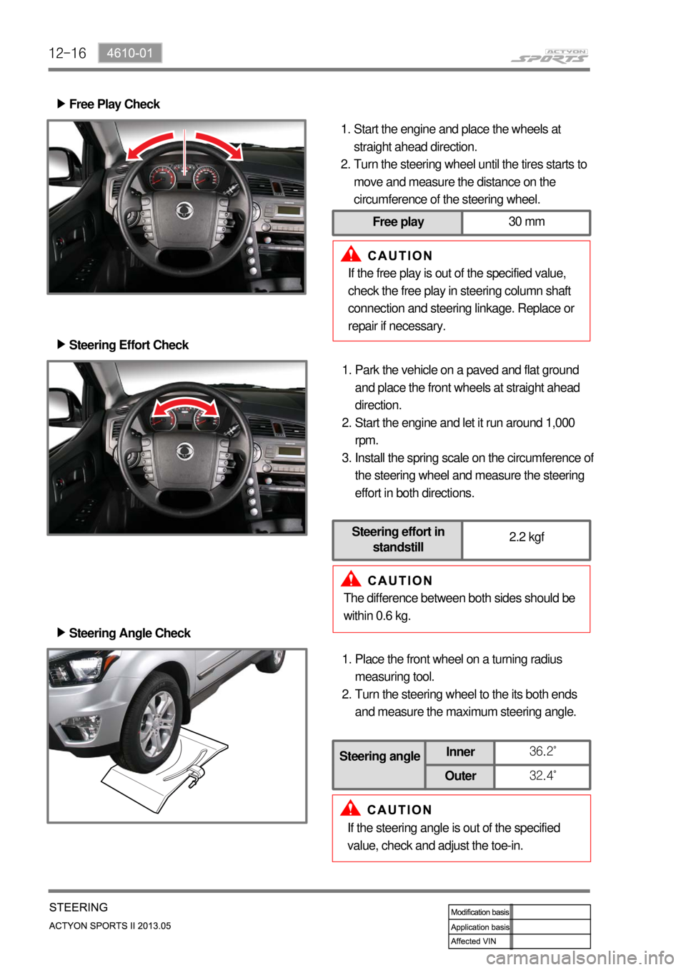
The difference between both sides should be
within 0.6 kg.Park the vehicle on a paved and flat ground
and place the front wheels at straight ahead
direction.
Start the engine and let it run around 1,000
rpm.
Install the spring scale on the circumference o
f
the steering wheel and measure the steering
effort in both directions. 1.
2.
3. Steering Effort Check ▶
Steering Angle Check ▶
Place the front wheel on a turning radius
measuring tool.
Turn the steering wheel to the its both ends
and measure the maximum steering angle. 1.
2.
If the steering angle is out of the specified
value, check and adjust the toe-in.
Steering angleInner36.2˚
Outer32.4˚
Free Play Check ▶
Start the engine and place the wheels at
straight ahead direction.
Turn the steering wheel until the tires starts to
move and measure the distance on the
circumference of the steering wheel. 1.
2.
If the free play is out of the specified value,
check the free play in steering column shaft
connection and steering linkage. Replace or
repair if necessary.
Free play30 mm
Steering effort in
standstill2.2 kgf
Page 646 of 751
12-174610-01
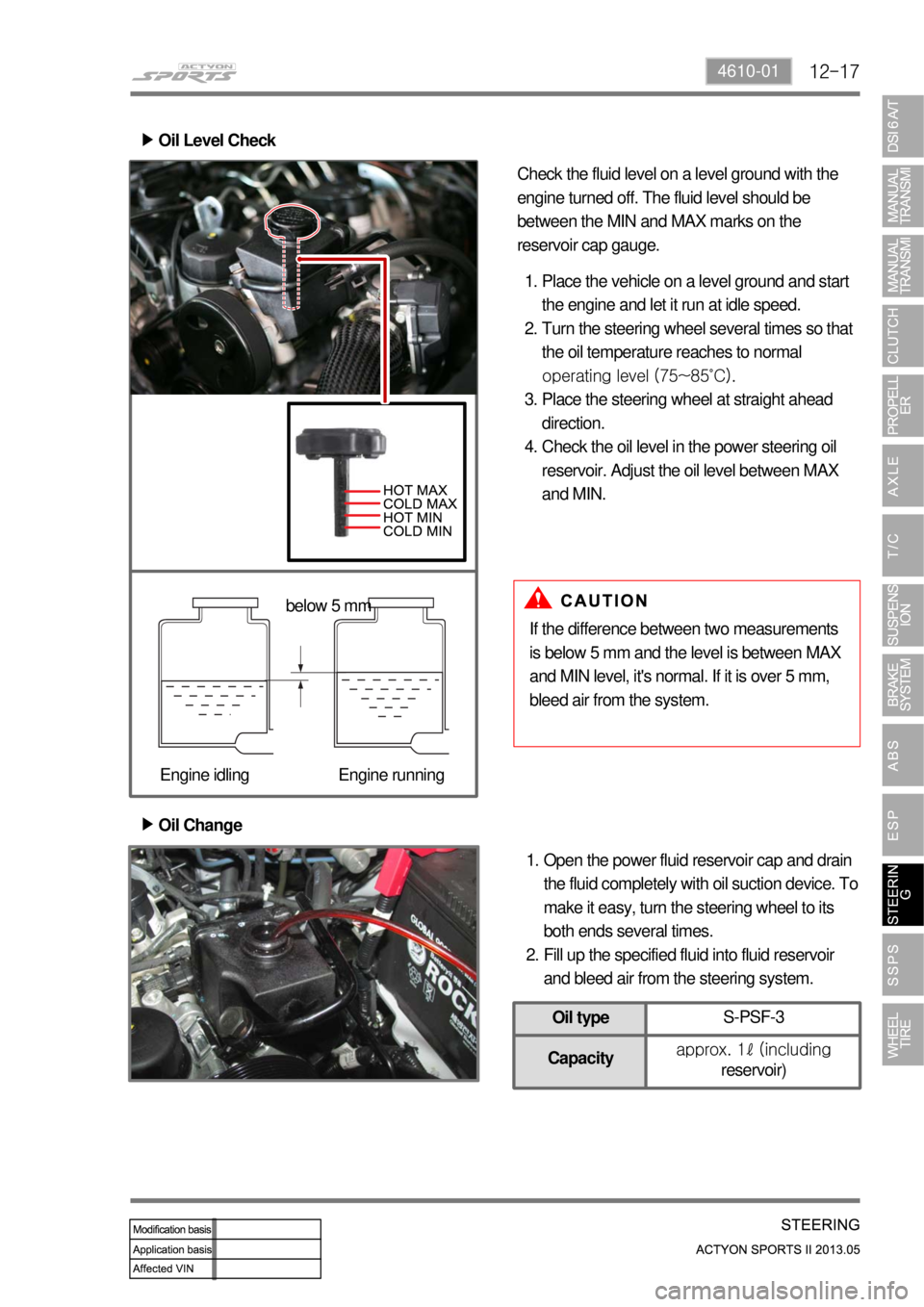
Oil Change ▶
Open the power fluid reservoir cap and drain
the fluid completely with oil suction device. To
make it easy, turn the steering wheel to its
both ends several times.
Fill up the specified fluid into fluid reservoir
and bleed air from the steering system. 1.
2. Oil Level Check ▶
Place the vehicle on a level ground and start
the engine and let it run at idle speed.
Turn the steering wheel several times so that
the oil temperature reaches to normal
operating level (75~85˚C).
Place the steering wheel at straight ahead
direction.
Check the oil level in the power steering oil
reservoir. Adjust the oil level between MAX
and MIN. 1.
2.
3.
4.
If the difference between two measurements
is below 5 mm and the level is between MAX
and MIN level, it's normal. If it is over 5 mm,
bleed air from the system. Check the fluid level on a level ground with the
engine turned off. The fluid level should be
between the MIN and MAX marks on the
reservoir cap gauge.
below 5 mm
Engine idling Engine running
Oil typeS-PSF-3
Capacityapprox. 1ℓ (including
reservoir)
Page 647 of 751

12-18
Air Bleeding ▶
Lift up the vehicle very carefully.
Turn the steering wheel to its both ends
several times and add the oil up to MAX line
in the steering oil reservoir.
Periodically crank the starting motor and turn
the steering wheel to its both ends without
any interruption.
Check the oil level again. If the oil level is
fluctuated, repeat the procedures from step 3
to step 5.
Start the engine.
Turn the steering wheel to its both ends until
any bubble can be found in the steering oil
reservoir.
Perform the test drive and check the steering
wheel for normal operation and noise.
If the oil level abruptly goes up, bleed the air
from the system again. 1.
2.
3.
4.
5.
6.
7.
8.
The air bleeding should be done after servicing
the power steering system and when the
difference between two measurements (cooled
and normal temperature) is prominent.
Max
Min
Normal Abnormal
If the air bleeding is not properly performed,
the life span of the power steering pump
may be shortened. -