ESP SSANGYONG NEW ACTYON SPORTS 2013 Owner's Manual
[x] Cancel search | Manufacturer: SSANGYONG, Model Year: 2013, Model line: NEW ACTYON SPORTS, Model: SSANGYONG NEW ACTYON SPORTS 2013Pages: 751, PDF Size: 72.63 MB
Page 224 of 751
15-24
This is done periodically under certain operating conditions. When the resetting is finished, the new
minimum pulse value replaces the value obtained during the previous resetting. The first MDP value is
provided by the C3I. Each resetting then allows the closed loop of the MDP to be updated according to
the deviation of the injector.
B. Detection of leaks in the cylinders
The accelerometer is also used to detect any injector which may have stuck open. The detection
principle is based on monitoring the ratio. If there is a leak in the cylinder, the accumulated fuel self-
ignites as soon as the temperature and pressure conditions are favorable (high engine speed, high load
and small leak).
This combustion is set off at about 20 degrees before TDC and before main injection.
The ratio therefore increases considerably in the detection window. It is this increase which allows the
leaks to be detected. The threshold beyond which a fault is signaled is a percentage of the maximum
possible value of the ratio.
Because of the severity of the recovery process (engine shut-down), the etection must be extremely
robust.
An increase in the ratio can be the consequence of various causes:
Pilot injection too much
Main combustion offset
Fuel leak in the cylinder -
-
-
If the ratio becomes too high, the strategy initially restricts the pilot injection flow and retards the main
injection. If the ratio remains high despite these interventions, this shows that a real leak is present, a
fault is signaled and the engine is shut down.
C. Detection of an accelerometer fault
This strategy permits the detection of a fault in the sensor or in the wiring loom connecting the sensor to
the ECU.
It is based on detection of the combustion. When the engine is idling, the detection window is set too low
for the combustion caused by the main injection. If the ratio increases, this shows that the knock sensor
is working properly, but otherwise a fault is signaled to indicate a sensor failure. The recovery modes
associated with this fault consist of inhibition of the pilot injection and discharge through the injectors.
Page 229 of 751
15-290000-00
(9) EGR control
A. Overview
The EGR (Electric-Exhaust Gas Recirculation) valve reduces the NOx emission level by recirculating
some of the exhaust gas to the intake system.
To meet Euro-V regulation, the capacity and response rate of E-EGR valve in D20DTR engine have
been greatly improved. The EGR cooler with high capacity reduces the Nox, and the bypass valve
reduces the CO and HC due to EGR gas before warming up.
Also, the engine ECU adjusts the E-EGR opening by using the air mass signal through HFM sensor. If
the exhaust gas gets into the intake manifold when the EGR valve is open, the amount of fresh air
through HFM sensor should be decresed.
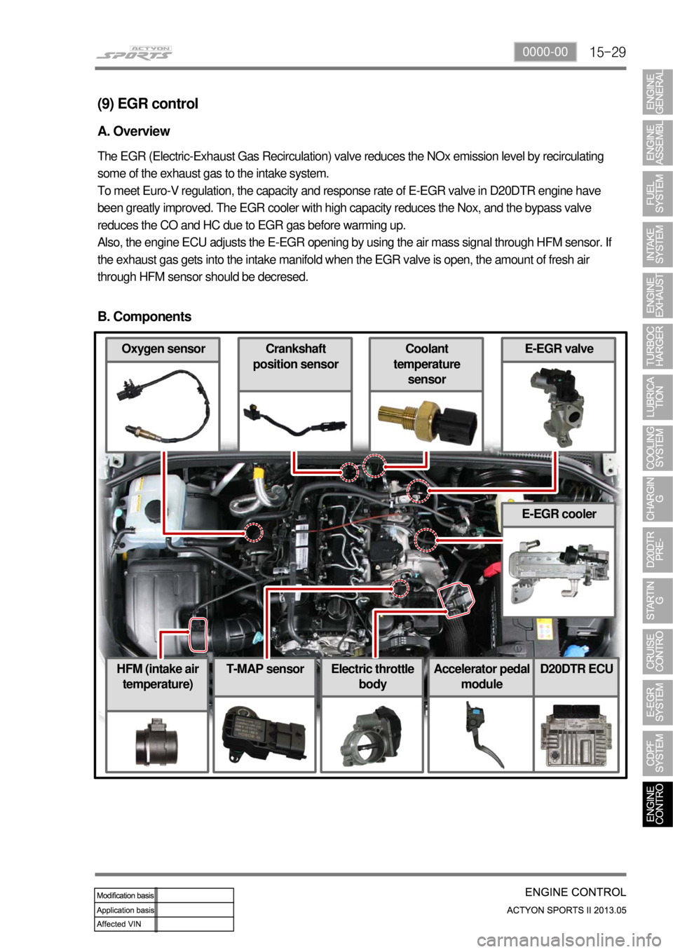
B. Components
E-EGR cooler
Accelerator pedal
moduleD20DTR ECU
Coolant
temperature
sensorOxygen sensor
HFM (intake air
temperature)Electric throttle
body
Crankshaft
position sensorE-EGR valve
T-MAP sensor
Page 275 of 751
02-6
1) Starting Mode
When the ignition is turned ON, the ECM turns the fuel pump relay on for 1 second. The fuel pump then
builds fuel pressure. The ECM also checks the Engine Coolant Temperature (ECT) sensor and the
Throttle Position (TP) sensor and determines the proper air/fuel ratio for starting the engine. This ranges
from1.5 to 1 at -36 °C (-33 °F) coolant temperature to 14.7 to 1 at 94 °C (201 °F) coolant
temperature. The ECM controls the amountof fuel delivered in the starting mode by changing how long
the fuel injector is turned on and off. This is done by ''pulsing" the fuel injectors for very short times.
2) Run Mode
The run mode has two conditions called ''open loop" and ''closed loop".
3) Open Loop
When the engine is first started and it is above 690 rpm, the system goes into "open loop" operation. In
"open loop", the ECM ignores the signal from the HO2S and calculates the air/fuel ratio based on inputs
from the ECT sensor and the MAF sensor. The ECM stays in "open loop" until the following conditions
are met:
The O2 has a varying voltage output, showing that it is hot enough to operate properly.
The ECT sensor is above a specified temperature (22.5 °C).
A specific amount of time has elapsed after starting the engine. -
-
-
4) Closed Loop
The specific values for the above conditions vary with different engines and are stored in the
Electronically Erasable Programmable Read-Only Memory (EEPROM).
When these conditions are met, the system goes into "closed loop" operation. In "closed loop", the ECM
calculates the air/fuel ratio (fuel injector on- time) based on the signals from the O2 sensors. This allows
the air/fuel ratio to stay very close to 14.7 to 1.
5) Acceleration Mode
The ECM responds to rapid changes in throttle position and airflow and provides extra fuel.
6) Deceleration Mode
The ECM responds to changes in throttle position and airflow and reduces the amount of fuel. When
deceleration is very fast, the ECM can cut off fuel completely for short periods of time.
Page 308 of 751
01-98410-02
5. OPERATING PROCESS OF ICM BOX
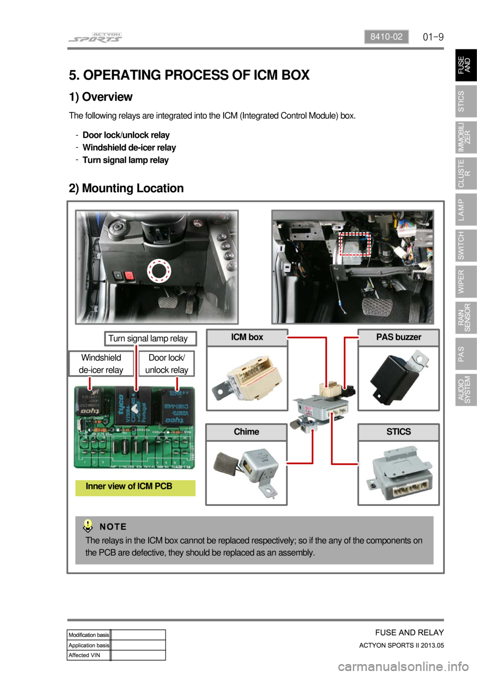
The following relays are integrated into the ICM (Integrated Control Module) box.
Door lock/unlock relay
Windshield de-icer relay
Turn signal lamp relay -
-
-
1) Overview
2) Mounting Location
Door lock/
unlock relay
Turn signal lamp relay
Windshield
de-icer relay
Inner view of ICM PCB
PAS buzzer
Chime
ICM box
STICS
The relays in the ICM box cannot be replaced respectively; so if the any of the components on
the PCB are defective, they should be replaced as an assembly.
Page 309 of 751
01-10
3) Operating Process by Power Supply of ICM Box
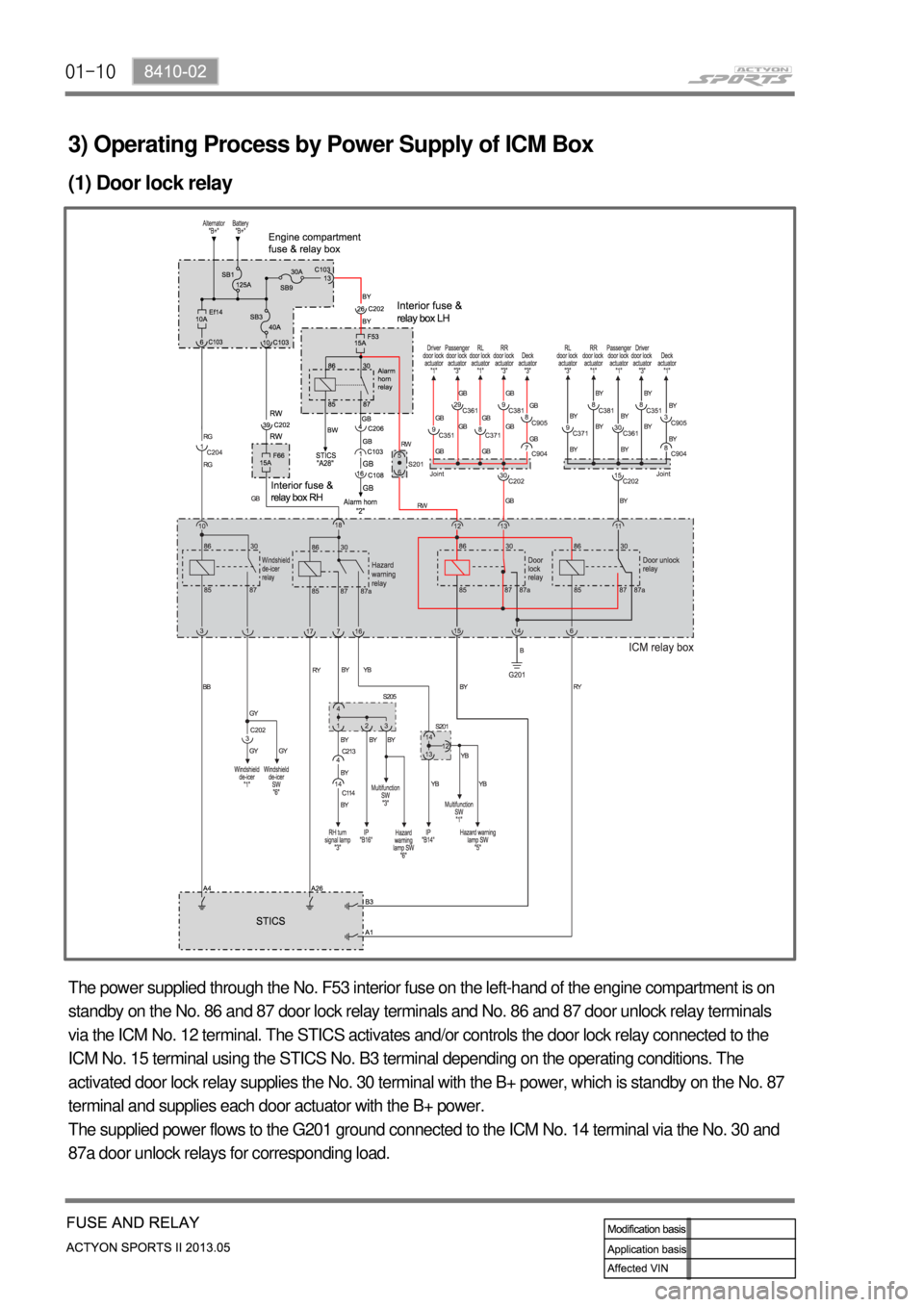
(1) Door lock relay
The power supplied through the No. F53 interior fuse on the left-hand of the engine compartment is on
standby on the No. 86 and 87 door lock relay terminals and No. 86 and 87 door unlock relay terminals
via the ICM No. 12 terminal. The STICS activates and/or controls the door lock relay connected to the
ICM No. 15 terminal using the STICS No. B3 terminal depending on the operating conditions. The
activated door lock relay supplies the No. 30 terminal with the B+ power, which is standby on the No. 87
terminal and supplies each door actuator with the B+ power.
The supplied power flows to the G201 ground connected to the ICM No. 14 terminal via the No. 30 and
87a door unlock relays for corresponding load.
Page 310 of 751

01-118410-02
(2) Door unlock relay
The supply power is on standby in the same way as the door lock relay, and the STICS activates and/or
controls the door unlock relay connected to the ICM No. 6 terminal using the STICS No. A1 terminal
depending on the operating conditions. The activated door unlock relay supplies the No. 30 terminal with
the B+ power, which is standby on the No. 87 terminal and supplies each door actuator with the B+
power.
The supplied power flows to the G201 ground connected to the ICM No. 14 terminal via the No. 30 and
87a door lock relays for corresponding load.
Page 311 of 751

01-12
(3) Turn signal lamp (Hazard warning lamp operation)
The B+ power supplied through the No. F66 interior fuse on the right-hand of the engine compartment is
on standby on the No. 30 and 86 hazard warning lamp relay terminals via the ICM No. 18 terminal.
The STICS activates and/or controls the hazard warning lamp relay using the No. A26 terminal
depending on the operating conditions. The activated relay supplies the No. 87 and 87a terminals with
the power, which is on standby on the No. 30 hazard warning lamp relay terminal.
The supplied power flows to the corresponding circuit via the No. 7 and 16 ICM terminals.
Page 329 of 751

02-198710-01
If the wiper does not operate at high speed even in heavy rain, check th\
e pins 1 and 2.
In other words, the wiper should operate at high speed when grounding th\
e pins 1 and 2.Symptom 5. The wiper does not operate at high speed even in heavy rain.
Symptom 6. The wiper responses are too fast or slow.
Check whether the variable resistance knob on the multifunction wiper sw\
itch is set in "FAST"
or "SLOW".
Notify that the customer can select the sensitivity by selecting the variable resistance value.
And, select a proper stage.
Page 345 of 751
02-358710-01
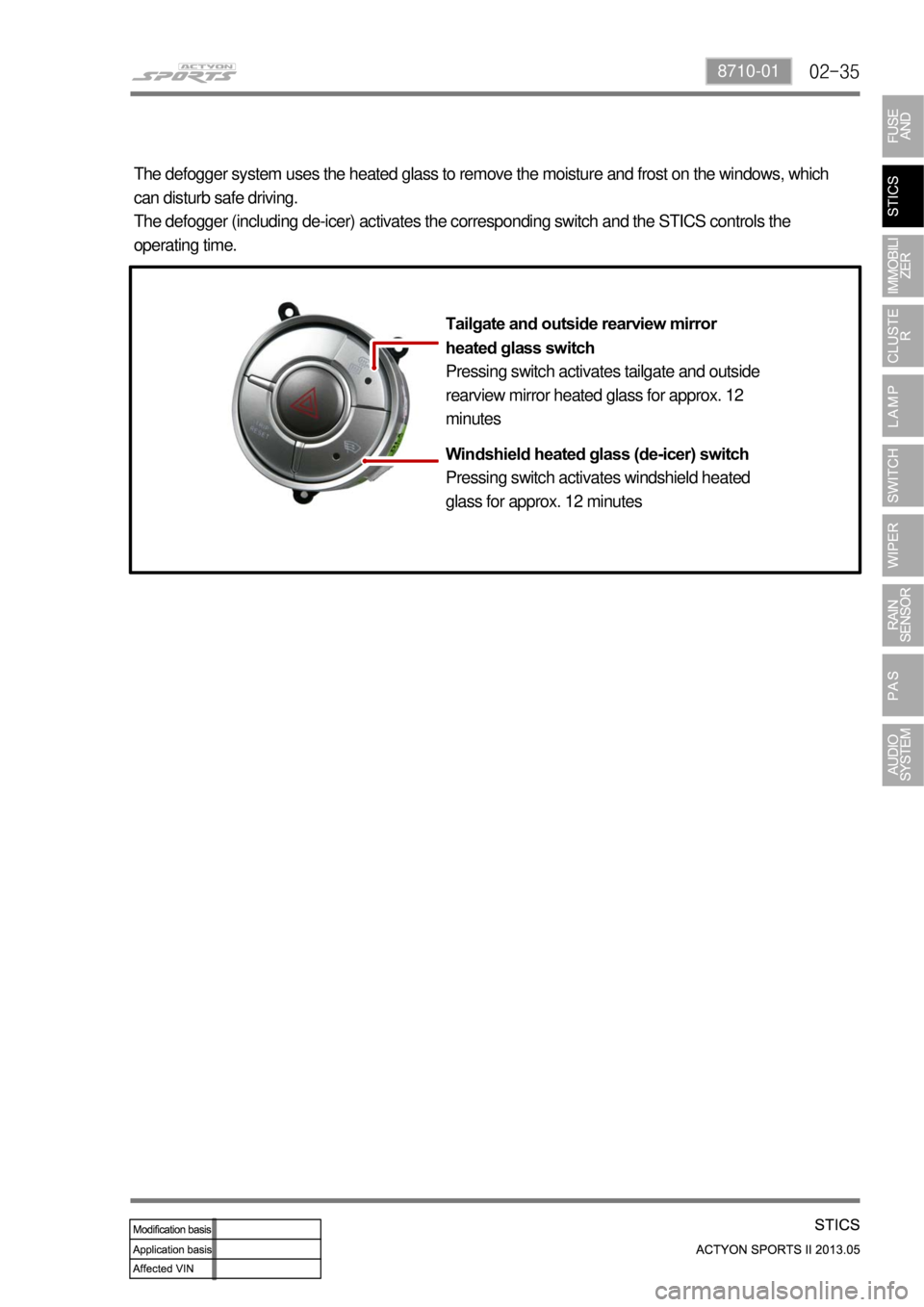
The defogger system uses the heated glass to remove the moisture and fro\
st on the windows, which
can disturb safe driving.
The defogger (including de-icer) activates the corresponding switch an\
d the STICS controls the
operating time.Tailgate and outside rearview mirror
heated glass switch
Pressing switch activates tailgate and outside
rearview mirror heated glass for approx. 12
minutes
Windshield heated glass (de-icer) switch
Pressing switch activates windshield heated
glass for approx. 12 minutes
Page 354 of 751
02-44
2. STICS CONTROL REGARDING THEFT WARNING ALARM
1) Armed mode
The followings are definition of DOOR OPEN/CLOSE and DOOR LOCK/UNLOCK in\
respect of theft
deterrent system.
-
DOOR OPEN and DOOR CLOSE DOOR OPEN:
- Any of all door switches (including engine hood, driver's door, passenge\
r's door or
rear door) is in "OPEN" position.
DOOR CLOSE:
- All door switches (including engine hood, driver's door, passenger's doo\
r, rear
door and tailgate) are in "CLOSE" position.
The door lock/unlock operation does not affect the engine hood.
OPEN/CLOSE of the dech tailgate does not affect entering the armed mode.\
In other words, when the hood and front/rear door are closed even if the\
dech tailgate is open, the
vehicle can enter the armed mode.
-
-
DOOR LOCK & DOOR UNLOCK DOOR LOCK:
-
Indicates that driver's, passenger's and rear door and tailgate lock swi\
tches are in
LOCK positions.
DOOR UNLOCK:
- Indicates that driver's, passenger's or rear door or tailgate lock switc\
hes are in
UNLOCK positions.
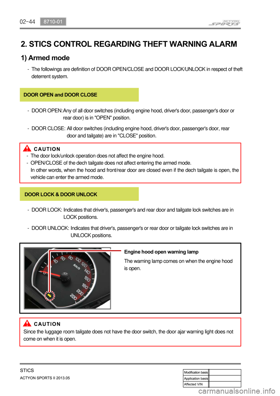
Engine hood open warning lamp
The warning lamp comes on when the engine hood
is open.
Since the luggage room tailgate does not have the door switch, the door ajar warning light does not
come on when it is open.