sensor SSANGYONG NEW ACTYON SPORTS 2013 Repair Manual
[x] Cancel search | Manufacturer: SSANGYONG, Model Year: 2013, Model line: NEW ACTYON SPORTS, Model: SSANGYONG NEW ACTYON SPORTS 2013Pages: 751, PDF Size: 72.63 MB
Page 257 of 751
01-8
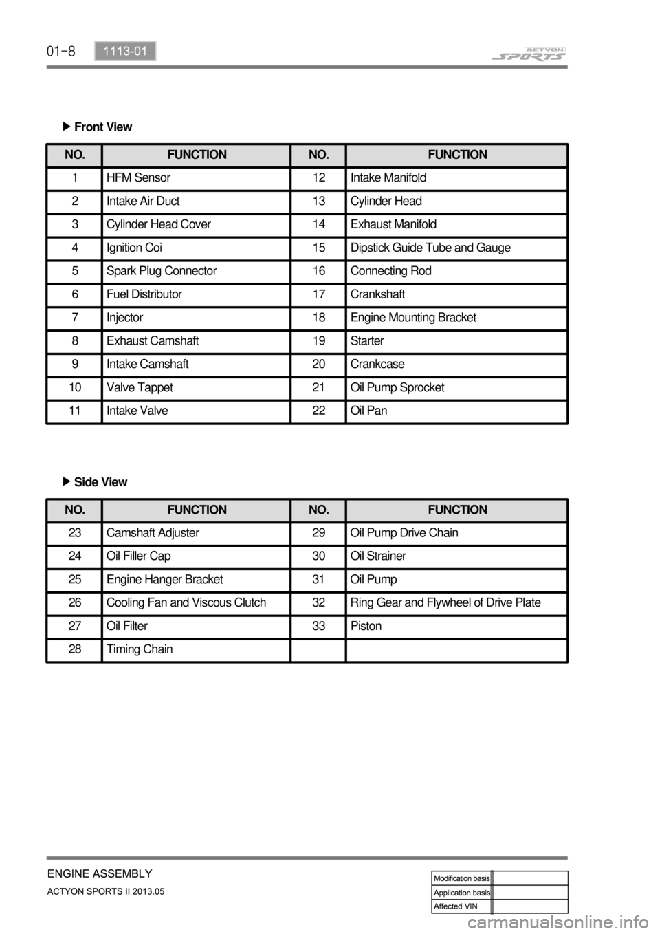
Front View ▶
NO. FUNCTION NO. FUNCTION
1 HFM Sensor 12 Intake Manifold
2 Intake Air Duct 13 Cylinder Head
3 Cylinder Head Cover 14 Exhaust Manifold
4 Ignition Coi 15 Dipstick Guide Tube and Gauge
5 Spark Plug Connector 16 Connecting Rod
6 Fuel Distributor 17 Crankshaft
7 Injector 18 Engine Mounting Bracket
8 Exhaust Camshaft 19 Starter
9 Intake Camshaft 20 Crankcase
10 Valve Tappet 21 Oil Pump Sprocket
11 Intake Valve 22 Oil Pan
NO. FUNCTION NO. FUNCTION
23 Camshaft Adjuster 29 Oil Pump Drive Chain
24 Oil Filler Cap 30 Oil Strainer
25 Engine Hanger Bracket 31 Oil Pump
26 Cooling Fan and Viscous Clutch 32 Ring Gear and Flywheel of Drive Plate
27 Oil Filter 33 Piston
28 Timing Chain
Side View ▶
Page 274 of 751
02-52211-06
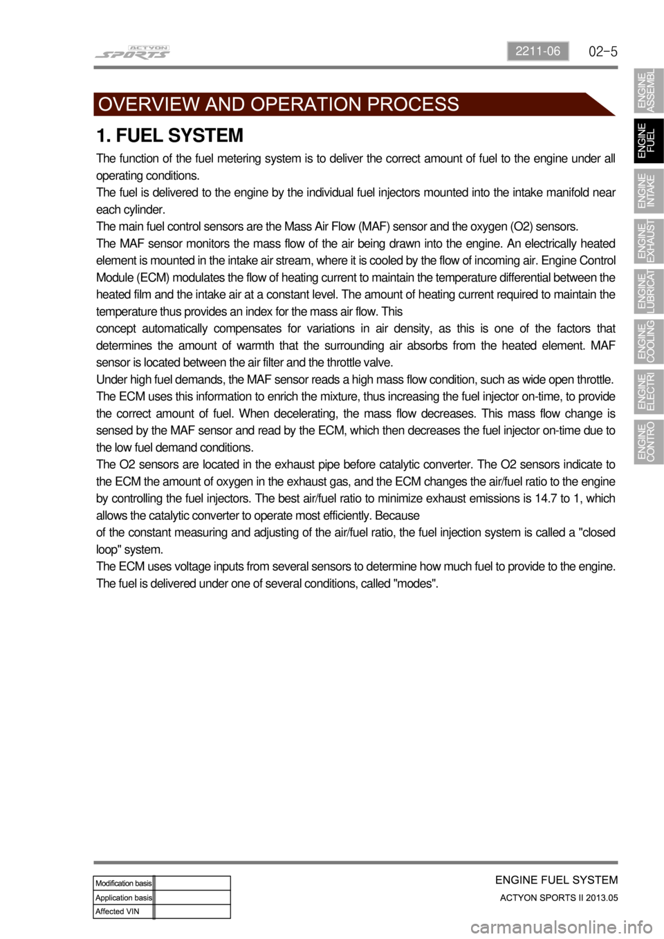
1. FUEL SYSTEM
The function of the fuel metering system is to deliver the correct amount of fuel to the engine under all
operating conditions.
The fuel is delivered to the engine by the individual fuel injectors mounted into the intake manifold nea
r
each cylinder.
The main fuel control sensors are the Mass Air Flow (MAF) sensor and the oxygen (O2) sensors.
The MAF sensor monitors the mass flow of the air being drawn into the engine. An electrically heated
element is mounted in the intake air stream, where it is cooled by the flow of incoming air. Engine Control
Module (ECM) modulates the flow of heating current to maintain the temperature differential between the
heated film and the intake air at a constant level. The amount of heating current required to maintain the
temperature thus provides an index for the mass air flow. This
concept automatically compensates for variations in air density, as this is one of the factors that
determines the amount of warmth that the surrounding air absorbs from the heated element. MAF
sensor is located between the air filter and the throttle valve.
Under high fuel demands, the MAF sensor reads a high mass flow condition, such as wide open throttle.
The ECM uses this information to enrich the mixture, thus increasing the fuel injector on-time, to provide
the correct amount of fuel. When decelerating, the mass flow decreases. This mass flow change is
sensed by the MAF sensor and read by the ECM, which then decreases the fuel injector on-time due to
the low fuel demand conditions.
The O2 sensors are located in the exhaust pipe before catalytic converter. The O2 sensors indicate to
the ECM the amount of oxygen in the exhaust gas, and the ECM changes the air/fuel ratio to the engine
by controlling the fuel injectors. The best air/fuel ratio to minimize exhaust emissions is 14.7 to 1, which
allows the catalytic converter to operate most efficiently. Because
of the constant measuring and adjusting of the air/fuel ratio, the fuel injection system is called a "closed
loop" system.
The ECM uses voltage inputs from several sensors to determine how much fuel to provide to the engine.
The fuel is delivered under one of several conditions, called "modes".
Page 275 of 751
02-6
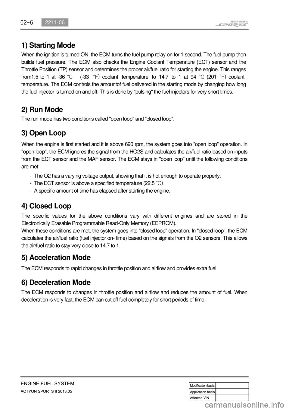
1) Starting Mode
When the ignition is turned ON, the ECM turns the fuel pump relay on for 1 second. The fuel pump then
builds fuel pressure. The ECM also checks the Engine Coolant Temperature (ECT) sensor and the
Throttle Position (TP) sensor and determines the proper air/fuel ratio for starting the engine. This ranges
from1.5 to 1 at -36 °C (-33 °F) coolant temperature to 14.7 to 1 at 94 °C (201 °F) coolant
temperature. The ECM controls the amountof fuel delivered in the starting mode by changing how long
the fuel injector is turned on and off. This is done by ''pulsing" the fuel injectors for very short times.
2) Run Mode
The run mode has two conditions called ''open loop" and ''closed loop".
3) Open Loop
When the engine is first started and it is above 690 rpm, the system goes into "open loop" operation. In
"open loop", the ECM ignores the signal from the HO2S and calculates the air/fuel ratio based on inputs
from the ECT sensor and the MAF sensor. The ECM stays in "open loop" until the following conditions
are met:
The O2 has a varying voltage output, showing that it is hot enough to operate properly.
The ECT sensor is above a specified temperature (22.5 °C).
A specific amount of time has elapsed after starting the engine. -
-
-
4) Closed Loop
The specific values for the above conditions vary with different engines and are stored in the
Electronically Erasable Programmable Read-Only Memory (EEPROM).
When these conditions are met, the system goes into "closed loop" operation. In "closed loop", the ECM
calculates the air/fuel ratio (fuel injector on- time) based on the signals from the O2 sensors. This allows
the air/fuel ratio to stay very close to 14.7 to 1.
5) Acceleration Mode
The ECM responds to rapid changes in throttle position and airflow and provides extra fuel.
6) Deceleration Mode
The ECM responds to changes in throttle position and airflow and reduces the amount of fuel. When
deceleration is very fast, the ECM can cut off fuel completely for short periods of time.
Page 276 of 751
02-72211-06
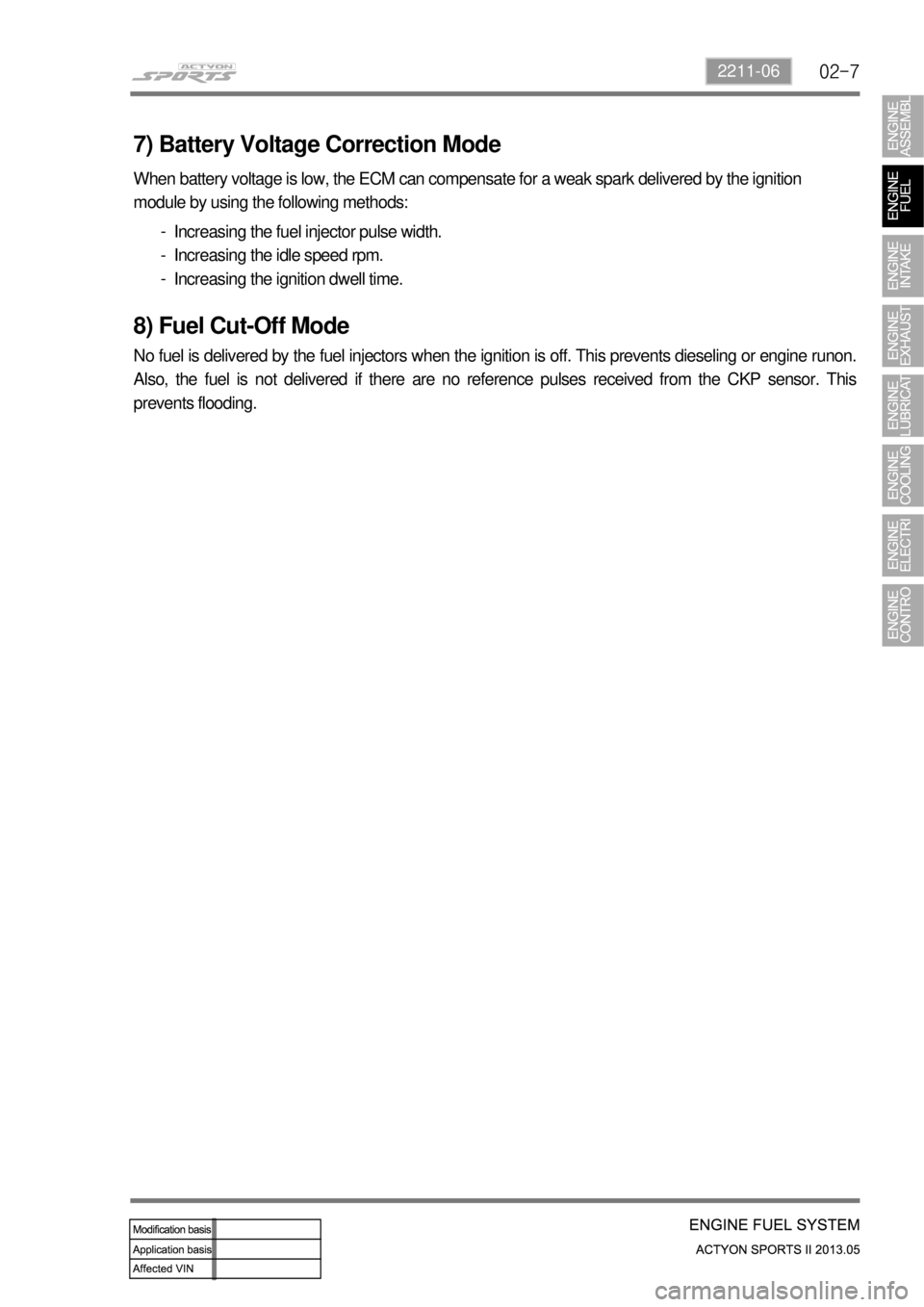
7) Battery Voltage Correction Mode
When battery voltage is low, the ECM can compensate for a weak spark delivered by the ignition
module by using the following methods:
Increasing the fuel injector pulse width.
Increasing the idle speed rpm.
Increasing the ignition dwell time. -
-
-
8) Fuel Cut-Off Mode
No fuel is delivered by the fuel injectors when the ignition is off. This prevents dieseling or engine runon.
Also, the fuel is not delivered if there are no reference pulses received from the CKP sensor. This
prevents flooding.
Page 284 of 751
06-4
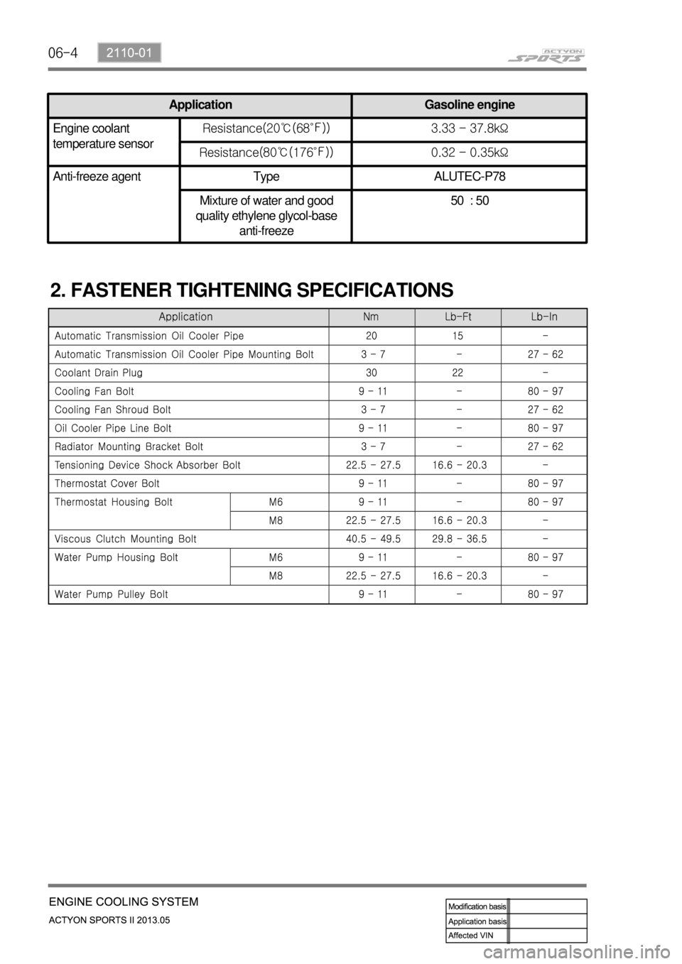
2. FASTENER TIGHTENING SPECIFICATIONS
Application Gasoline engine
Engine coolant
temperature sensorResistance(20℃(68℉)) 3.33 - 37.8kΩ
Resistance(80℃(176℉)) 0.32 - 0.35kΩ
Anti-freeze agent Type ALUTEC-P78
Mixture of water and good
quality ethylene glycol-base
anti-freeze50 : 50
Page 288 of 751
06-8
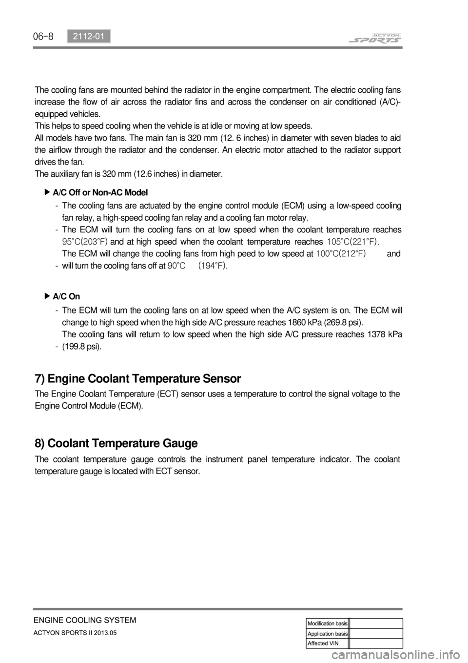
The cooling fans are mounted behind the radiator in the engine compartment. The electric cooling fans
increase the flow of air across the radiator fins and across the condenser on air conditioned (A/C)-
equipped vehicles.
This helps to speed cooling when the vehicle is at idle or moving at low speeds.
All models have two fans. The main fan is 320 mm (12. 6 inches) in diameter with seven blades to aid
the airflow through the radiator and the condenser. An electric motor attached to the radiator support
drives the fan.
The auxiliary fan is 320 mm (12.6 inches) in diameter.
A/C Off or Non-AC Model ▶
The cooling fans are actuated by the engine control module (ECM) using a low-speed cooling
fan relay, a high-speed cooling fan relay and a cooling fan motor relay.
The ECM will turn the cooling fans on at low speed when the coolant temperature reaches
95°C(203°F) and at high speed when the coolant temperature reaches 105°C(221°F).
The ECM will change the cooling fans from high peed to low speed at 100°C(212°F) and
will turn the cooling fans off at 90°C (194°F). -
-
-
A/C On ▶
The ECM will turn the cooling fans on at low speed when the A/C system is on. The ECM will
change to high speed when the high side A/C pressure reaches 1860 kPa (269.8 psi).
The cooling fans will return to low speed when the high side A/C pressure reaches 1378 kPa
(199.8 psi). -
-
7) Engine Coolant Temperature Sensor
The Engine Coolant Temperature (ECT) sensor uses a temperature to control the signal voltage to the
Engine Control Module (ECM).
8) Coolant Temperature Gauge
The coolant temperature gauge controls the instrument panel temperature indicator. The coolant
temperature gauge is located with ECT sensor.
Page 291 of 751

06-112112-01
5) Shutting-off Condition of the A/C Compressor
Coolant temperature ▶
When coolant temperature is below 20°C or over 115°C, engine speed is below 650 rpm or
over 4500 rpm for 4 seconds after engine starting, abrupt acceleration and A/C refrigerant
pressure sensor detecting the followings
A/C compressor is turned off when the refrigerant pressure is below 2.0 kg/cm2 and then is
turned on when the refrigerant pressure is over 2.4 kg/cm2.
A/C compressor is turned off when the refrigerant pressure is over 30 kg/cm2 and then is turned
on when the refrigerant pressure is below 21.4 kg/cm2. -
-
-
Page 302 of 751
01-38410-02
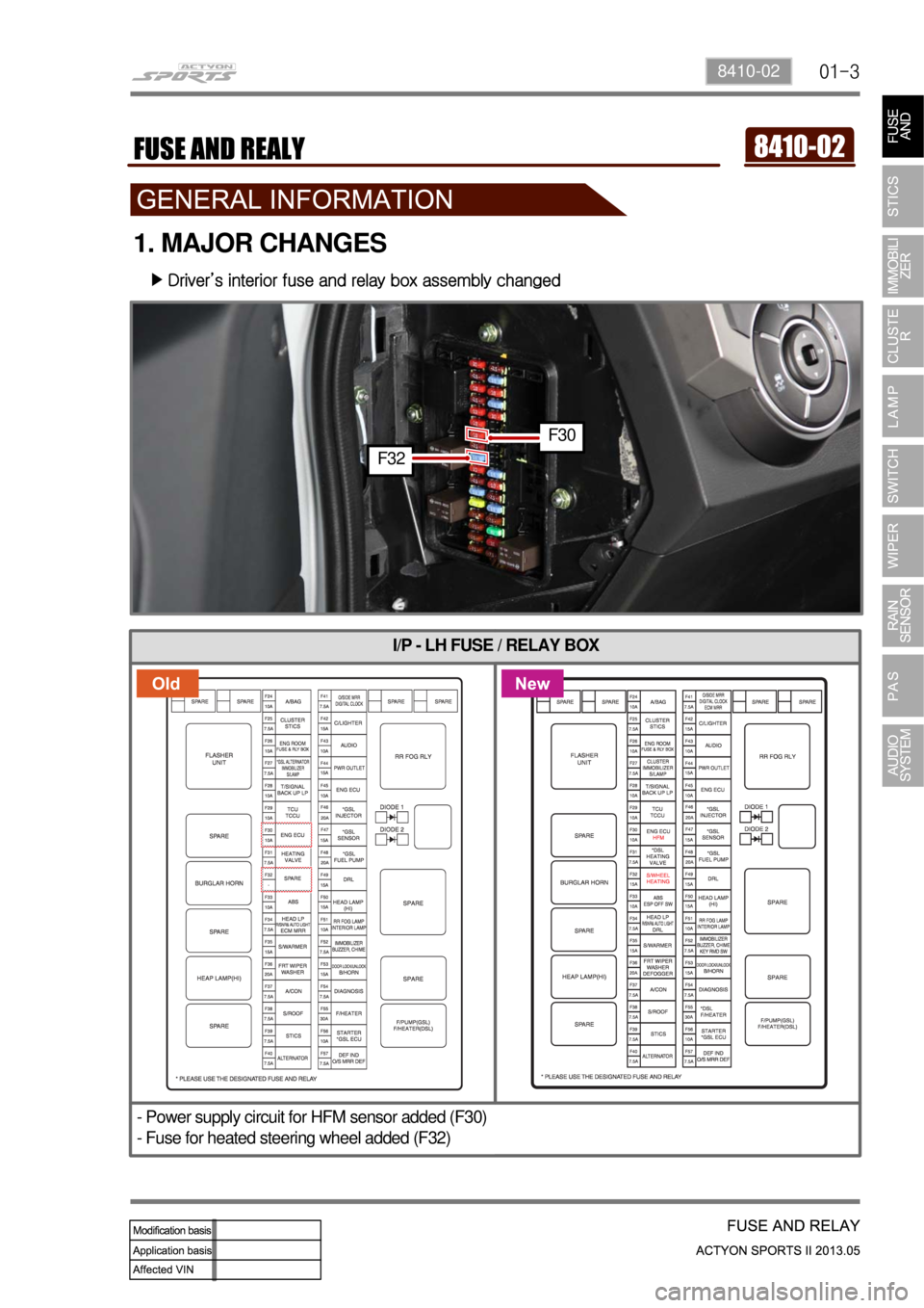
I/P - LH FUSE / RELAY BOX
- Power supply circuit for HFM sensor added (F30)
- Fuse for heated steering wheel added (F32)
1. MAJOR CHANGES
Driver’s interior fuse and relay box assembly changed ▶
F32
F30
Page 314 of 751
02-4
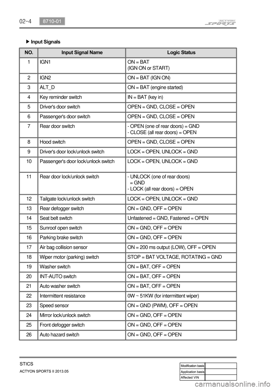
Input Signals
▶
NO.
Input Signal Name Logic Status
1 IGN1 ON = BAT
(IGN ON or START)
2 IGN2 ON = BAT (IGN ON)
3 ALT_D ON = BAT (engine started)
4 Key reminder switch IN = BAT (key in)
5 Driver's door switch OPEN = GND, CLOSE = OPEN
6 Passenger's door switch OPEN = GND, CLOSE = OPEN
7 Rear door switch - OPEN (one of rear doors) = GND
- CLOSE (all rear doors) = OPEN
8 Hood switch OPEN = GND, CLOSE = OPEN
9 Driver's door lock/unlock switch LOCK = OPEN, UNLOCK = GND
10 Passenger's door lock/unlock switch LOCK = OPEN, UNLOCK = GND
11 Rear door lock/unlock switch - UNLOCK (one of rear doors)
= GND
- LOCK (all rear doors) = OPEN
12 Tailgate lock/unlock switch LOCK = OPEN, UNLOCK = GND
13 Rear defogger switch ON = GND, OFF = OPEN
14 Seat belt switch Unfastened = GND, Fastened = OPEN
15 Sunroof open switch ON = GND, OFF = OPEN
16 Parking brake switch ON = GND, OFF = OPEN
17 Air bag collision sensor ON = 200 ms output (LOW), OFF = OPEN
18 Wiper motor (parking) switch STOP = BAT VOLTAGE, ROTATING = GND
19 Washer switch ON = BAT, OFF = OPEN
20 INT-AUTO switch ON = BAT, OFF = OPEN
21 Auto washer switch ON = BAT, OFF = OPEN
22 Intermittent resistance 0W ~ 51KW (for intermittent wiper)
23 Speed sensor ON = GND (PWM), OFF = OPEN
24 Mirror lock/unlock switch ON = GND, OFF = OPEN
25 Front defogger switch ON = GND, OFF = OPEN
26 Auto hazard switch ON = GND, OFF = OPEN
Page 315 of 751

02-58710-01
NO.Input Signal Name Logic Status
27 Central door lock switch ON = GND, OFF = OPEN
28 Multifunction auto light switch ON = GND, OFF = OPEN
29 Turn signal lamp switch ON = BAT/GND, OFF = OPEN
(approx. 5.1 V ~ 9.2 V)
30 Rain sensor ON = GND (DATA), OFF = BAT
31 Telematics ON = GND (DATA), OFF = BAT
32 Diagnosis ON = GND (DATA), OFF = BAT (KWP2000)