water pump SSANGYONG NEW REXTON 2012 User Guide
[x] Cancel search | Manufacturer: SSANGYONG, Model Year: 2012, Model line: NEW REXTON, Model: SSANGYONG NEW REXTON 2012Pages: 600, PDF Size: 73.29 MB
Page 294 of 600

0000-00
Intake/Exhaust Camshafts
2) Camshaft
(1) Overview
Hollow type camshaft contains cam, octagon cam, HP pump gear and intake/exhaust gears.
Camshaft operates the intake/exhaust valves, vacuum pump and HP pump, and transfers the engine
oil to vacuum pump through the internal oil passage.
(2) Location
Exhaust CamshaftExhaust Camshaft
Octagon cam
(for tooling)
Thrust journal
Connected to
vacuum pump
Intake Camshaft
Closed flow type water jacket (improving cooling performance)
Page 316 of 600
0000-00
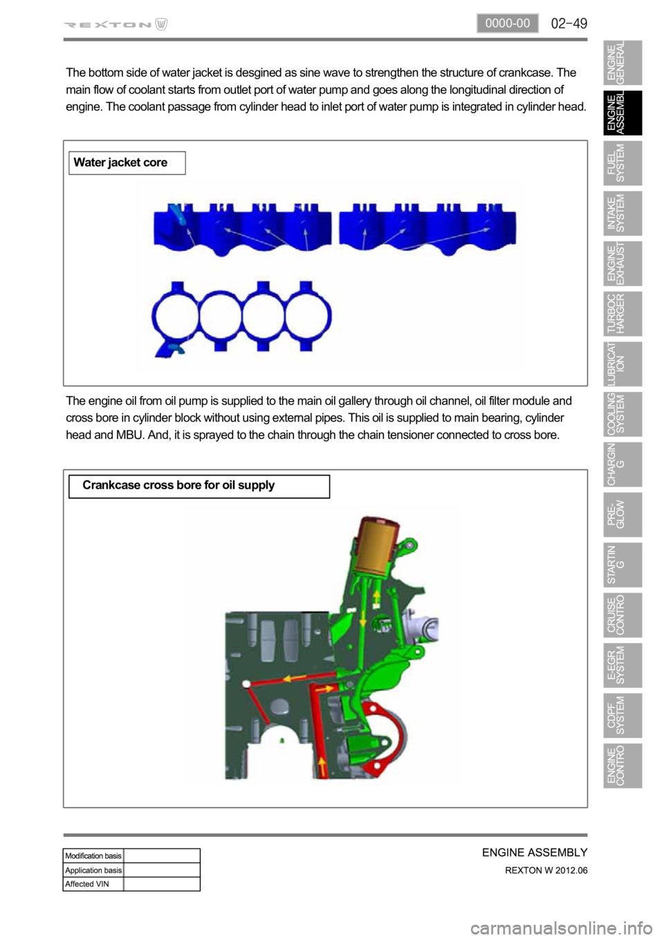
The bottom side of water jacket is desgined as sine wave to strengthen the structure of crankcase. The
main flow of coolant starts from outlet port of water pump and goes along the longitudinal direction of
engine. The coolant passage from cylinder head to inlet port of water pump is integrated in cylinder head.
The engine oil from oil pump is supplied to the main oil gallery through oil channel, oil filter module and
cross bore in cylinder block without using external pipes. This oil is supplied to main bearing, cylinder
head and MBU. And, it is sprayed to the chain through the chain tensioner connected to cross bore.
Crankcase cross bore for oil supply
Water jacket core
Page 317 of 600

2210-01
1. SPECIFICATION
Description Specification
Fuel Diesel
Fuel filterType Fuel heater + priming pump + water
separator integrated type
Filter type Changeable filter element type
Water accumulating capacity 200 cc
Heater capacity 250W 13.5V
Injector System pressure 1800 bar
High pressure fuel
pumpType Eccentric cam/Plunger type
Operating type Gear driven type
Normal operating temperature
Operating pressure 1800 bar
Operating temperature
Low pressure fuel
pumpType Vane type
Gear ratio (pump/engine) 0.5 : 1
Pressure 6 bar
Fuel tankCapacity 75 L
Material Steel
Fuel sender Single sender type
Change interval EU every 40,000 km
GEN every 45,000 km
Water separation
intervalEU every 20,000 km
GEN every 15,000 km
Page 334 of 600
(2) Di engine and its expected problems and remedies can be caused by
water in fuel
System supplement against paraffin separation
In case of Diesel fuel, paraffin, one of the elements, can be separated from fuel during winter and then
can stick on the fuel filter blocking fuel flow and causing difficult starting finally. Oil companies supply
summer fuel and winter fuel by differentiating mixing ratio of kerosene and other elements by region and
season. However, above phenomenon can be happened if stations have poor facilities or sell improper
fuel for the season. In case of DI engine, purity of fuel is very important factor to keep internal
preciseness of HP pump and injector.
Accordingly, more dense mesh than conventional fuel filter is used. To prevent fuel filter internal clogging
due to paraffin separation, SYMC is using fuel line that high pressure and temperature fuel injected by
injector returns through fuel filter to have an effect of built-in heater (see fuel system).
System supplement and remedy against water in fuel
As mentioned above, some gas stations supply fuel with excessive than specified water. In the
conventional IDI engine, excessive water in the fuel only causes dropping engine power or engine
hunting. However, fuel system in the DI engine consists of precise components so water in the fuel can
cause malfunctions of HP pump due to poor lubrication of pump caused by poor coating film during high
speed pumping and bacterization (under long period parking). To prevent problems can be caused by
excessive water in fuel, water separator is installed inside of fuel filter. When fuel is passing filter, water
that has relatively bigger specific gravity is accumulated on the bottom of the filter.
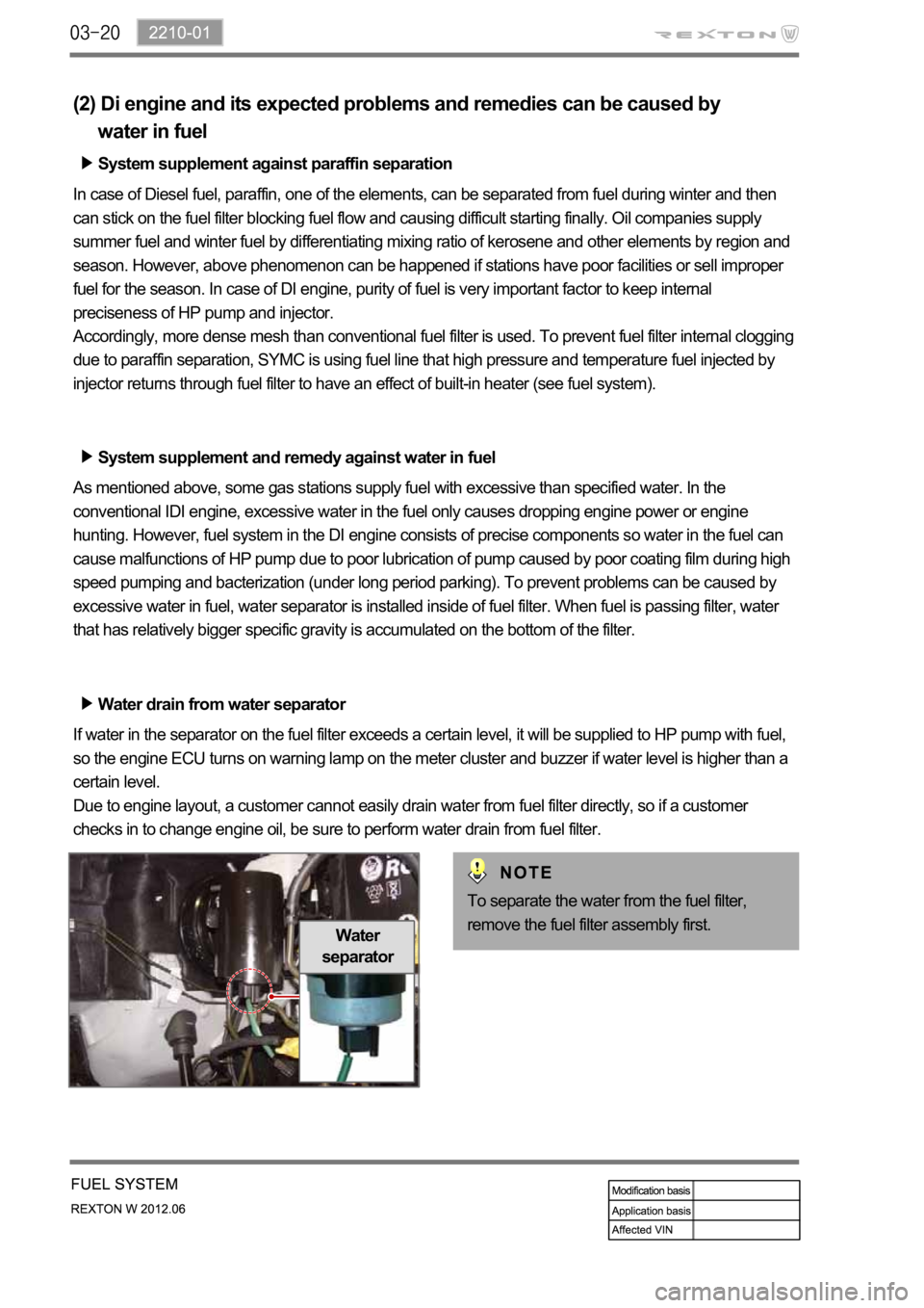
Water drain from water separator
If water in the separator on the fuel filter exceeds a certain level, it will be supplied to HP pump with fuel,
so the engine ECU turns on warning lamp on the meter cluster and buzzer if water level is higher than a
certain level.
Due to engine layout, a customer cannot easily drain water from fuel filter directly, so if a customer
checks in to change engine oil, be sure to perform water drain from fuel filter.
Water
separator
To separate the water from the fuel filter,
remove the fuel filter assembly first.
Page 337 of 600
2210-01
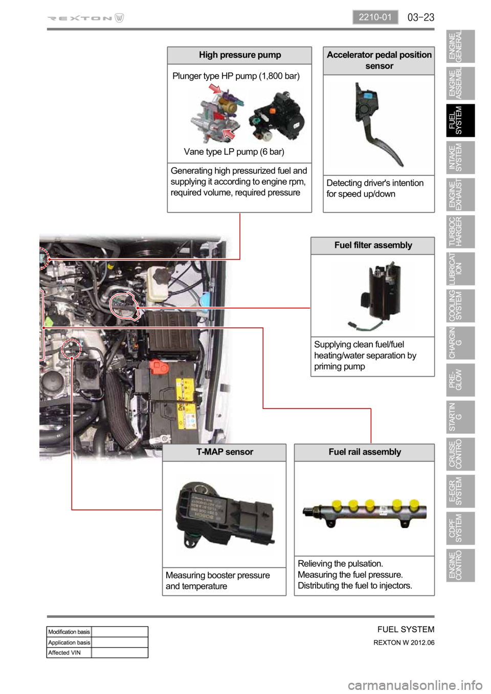
Accelerator pedal position
sensor
Detecting driver's intention
for speed up/down
Fuel rail assembly
Relieving the pulsation.
Measuring the fuel pressure.
Distributing the fuel to injectors.
Fuel filter assembly
Supplying clean fuel/fuel
heating/water separation by
priming pump
Plunger type HP pump (1,800 bar)
Vane type LP pump (6 bar)
T-MAP sensor
Measuring booster pressure
and temperature
High pressure pump
Generating high pressurized fuel and
supplying it according to engine rpm,
required volume, required pressure
Page 379 of 600
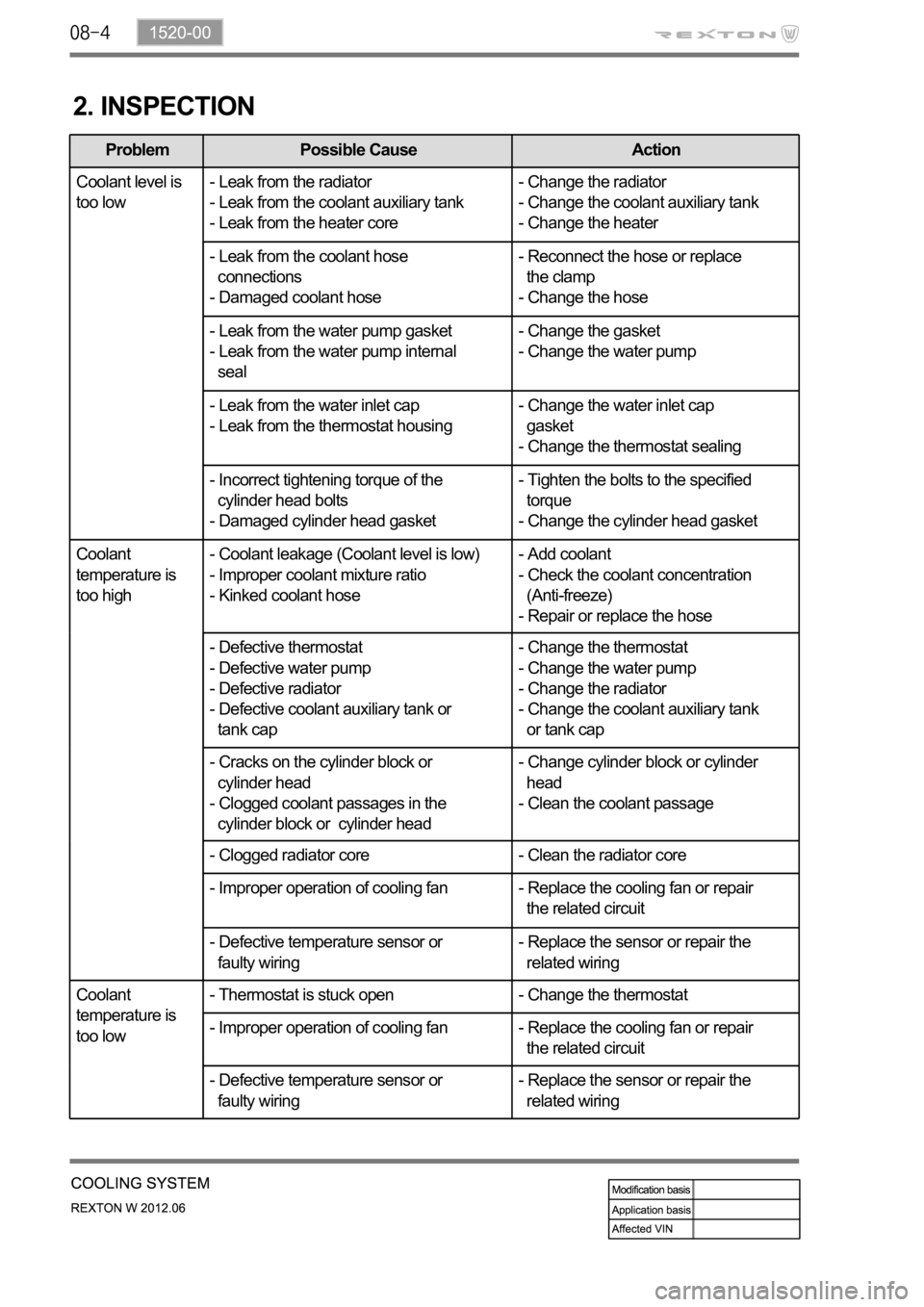
2. INSPECTION
Problem Possible Cause Action
Coolant level is
too low- Leak from the radiator
- Leak from the coolant auxiliary tank
- Leak from the heater core- Change the radiator
- Change the coolant auxiliary tank
- Change the heater
- Leak from the coolant hose
connections
- Damaged coolant hose- Reconnect the hose or replace
the clamp
- Change the hose
- Leak from the water pump gasket
- Leak from the water pump internal
seal- Change the gasket
- Change the water pump
- Leak from the water inlet cap
- Leak from the thermostat housing- Change the water inlet cap
gasket
- Change the thermostat sealing
- Incorrect tightening torque of the
cylinder head bolts
- Damaged cylinder head gasket- Tighten the bolts to the specified
torque
- Change the cylinder head gasket
Coolant
temperature is
too high- Coolant leakage (Coolant level is low)
- Improper coolant mixture ratio
- Kinked coolant hose- Add coolant
- Check the coolant concentration
(Anti-freeze)
- Repair or replace the hose
- Defective thermostat
- Defective water pump
- Defective radiator
- Defective coolant auxiliary tank or
tank cap- Change the thermostat
- Change the water pump
- Change the radiator
- Change the coolant auxiliary tank
or tank cap
- Cracks on the cylinder block or
cylinder head
- Clogged coolant passages in the
cylinder block or cylinder head- Change cylinder block or cylinder
head
- Clean the coolant passage
- Clogged radiator core - Clean the radiator core
- Improper operation of cooling fan - Replace the cooling fan or repair
the related circuit
- Defective temperature sensor or
faulty wiring- Replace the sensor or repair the
related wiring
Coolant
temperature is
too low- Thermostat is stuck open - Change the thermostat
- Improper operation of cooling fan - Replace the cooling fan or repair
the related circuit
- Defective temperature sensor or
faulty wiring- Replace the sensor or repair the
related wiring
Page 382 of 600

1520-00
3. CAUTIONS
If 100% of anti-freeze is added, the water pump vane can be damaged and thermal conductivity
can be decreased resulting in poor circulation in the cooling system which leads to overheated
engine.
Use of non-recommended coolant could cause damage to the cooling system and overheating of
the engine.
Opening the coolant reservoir cap while the engine is running or hot can cause burns by hot steam
or water.
To open the coolant reservoir cap, wrap the cap with a wet towel or thick cloth after the engine is
cooled down sufficiently.
If cool water is added to the heated engine, the engine or radiator can be deformed.
The anti-freeze in the coolant can damage the painted surface, so avoid the contact of the coolant
to the painted body.
The anti-freeze and water should be mixed in proper mixture ratio. Never add only water when
adding coolant.
If the anti-freeze content is too low, the coolant can be frozen while the engine can be overheated if
anti-freeze content is too high. -
-
-
-
-
-
-
-
Page 383 of 600

Water pump
The water pump is driven by the engine drive belt and supplies
the coolant to each area of the engine.
Coolant reservoir
Long life coolant is used.
Thermostat
When the engine coolant
starts to open (fully open at
flow to the radiator to maintain
the engine temperature.
1. SYSTEM DESCRIPTION
1) Overview
Water pump
Impeller vane Sealing
Oil filter module
Page 476 of 600
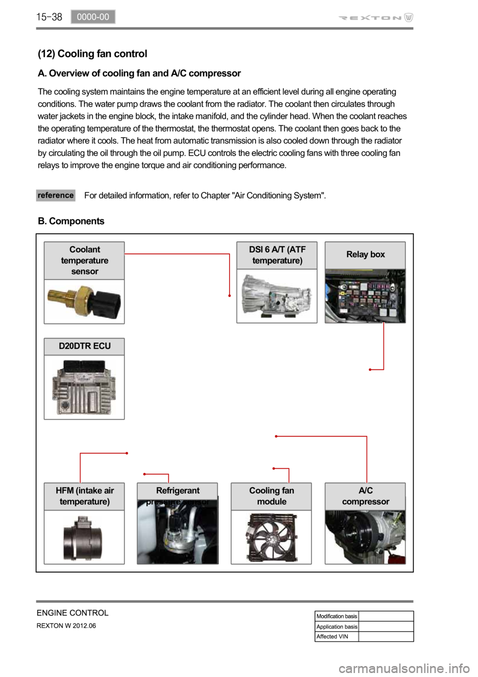
HFM (intake air
temperature)Cooling fan
module
DSI 6 A/T (ATF
temperature)Coolant
temperature
sensor
Refrigerant
pressure sensor
Relay box
(12) Cooling fan control
A. Overview of cooling fan and A/C compressor
The cooling system maintains the engine temperature at an efficient level during all engine operating
conditions. The water pump draws the coolant from the radiator. The coolant then circulates through
water jackets in the engine block, the intake manifold, and the cylinder head. When the coolant reaches
the operating temperature of the thermostat, the thermostat opens. The coolant then goes back to the
radiator where it cools. The heat from automatic transmission is also cooled down through the radiator
by circulating the oil through the oil pump. ECU controls the electric cooling fans with three cooling fan
relays to improve the engine torque and air conditioning performance.
For detailed information, refer to Chapter "Air Conditioning System".
B. Components
A/C
compressor
D20DTR ECU
Page 555 of 600

1520-01
1. COMPARISON IN COOLING SYSTEM FOR EACH ENGINE
For the D27DTP (POWER UP) engine, the cooling system is equipped with E-EGR cooler and the
water pump which its capacity is improved according to the additional coolant line in the cylinder
block. For the D27DT engine, the cooling system uses the fan clutch.
Cooling System for D27DTP (POWER UP) Engine