engine SSANGYONG RODIUS 2006 Owners Manual
[x] Cancel search | Manufacturer: SSANGYONG, Model Year: 2006, Model line: RODIUS, Model: SSANGYONG RODIUS 2006Pages: 444, PDF Size: 56.32 MB
Page 163 of 444

ELECTRIC GENERAL
0000-00
ELECTRIC GENERAL
GENERAL
1. LOCATIONS OF UNITS AND SENSORS
IN PASSENGER COMPARTMENT.........
2. SWITCHES, UNITS AND SENSORS IN
ENGINE COMPARTMENT (EXCEPT
ENGINE RELATED SENSORS AND
UNITS)...................................................
3. SWITCHES IN PASSENGER
COMPARTMENT...................................
4. SYSTEM LAYOUT (BASED ON DVD
SYSTEM EQUIPPED VEHICLE).............
5. WIRING HARNESS ARRANGEMENT.....
6. COMPONENTS LOCATOR....................
ELECTRIC GENERAL ELECTRIC GENERAL ELECTRIC GENERAL
4
6
8
10
12
13
Page 168 of 444
0-6
RODIUS 2007.07
0000-00
ELECTRIC GENERAL
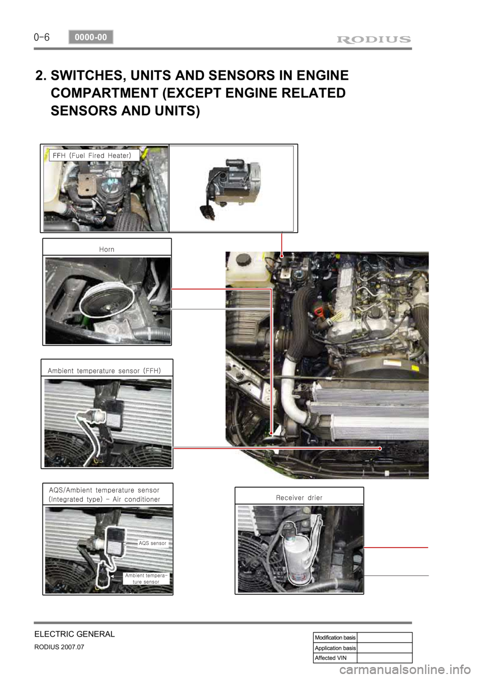
2. SWITCHES, UNITS AND SENSORS IN ENGINE
COMPARTMENT (EXCEPT ENGINE RELATED
SENSORS AND UNITS)
Page 169 of 444
0-7
ELECTRIC GENERAL
RODIUS 2007.07
0000-00
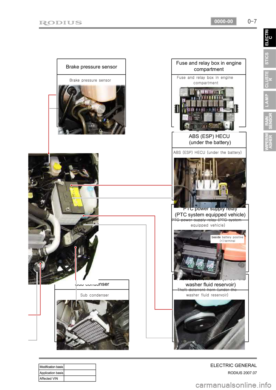
Sub condenser
Theft deterrent horn (under the washer fluid reservoir)
PTC power supply relay
(PTC system equipped vehicle)
ABS (ESP) HECU
(under the battery)
Fuse and relay box in engine compartmentBrake pressure sensor
Page 187 of 444
0-14
RODIUS 2007.07
8710-01
STICS
(3) Speed Sensitive INT (Intermittent) Wiper
For STICS without rain sensor, perform the following operation:
1. Controls the wiper intermittent operation by the values from vehicle speed and volume.
Calculates and converts the Intermittent interval automatically by using the vehicle speed
and INT VOLUME when the ignition switch is in “ON” position and the INT switch is in
“ON” position (the engine is running).
The wipers are operated in vehicle speed sensitive mode when turning the INT switch
to “ON” position with the engine running or starting the engine with the INT switch
positioned “ON”.
Intermittent interval (at 0 km/h): 3 ± 0.5 ~ 19 ± 2 seconds -
-
-
2. Vehicle speed calculation
[Input the vehicle speed]
It is calculated by the numbers of input pulses for one second.
1 [pulses/sec] = 60 [km/h] x 60 [sec] / 637 pulses = 1.41 [km/h]
3. VOLUME calculation
Calculates the INT VOLUME with 5 grades as shown in the table in next page. -
4. Pause time calculation
Pause time: the duration that wipers are stopped at parking position
Elapsed time: the duration after the wiper motor started to operate from parking position
The pause time is calculated by the vehicle speed and VOLUME value as shown in the
table in next page. -
-
-
If the pause time is below 1.0 second, the wipers operate without pause.
If the pause time is over 1.5 seconds, the wipers operate intermittently. ·
·
Page 200 of 444
0-27
STICS
RODIUS 2007.07
8710-01
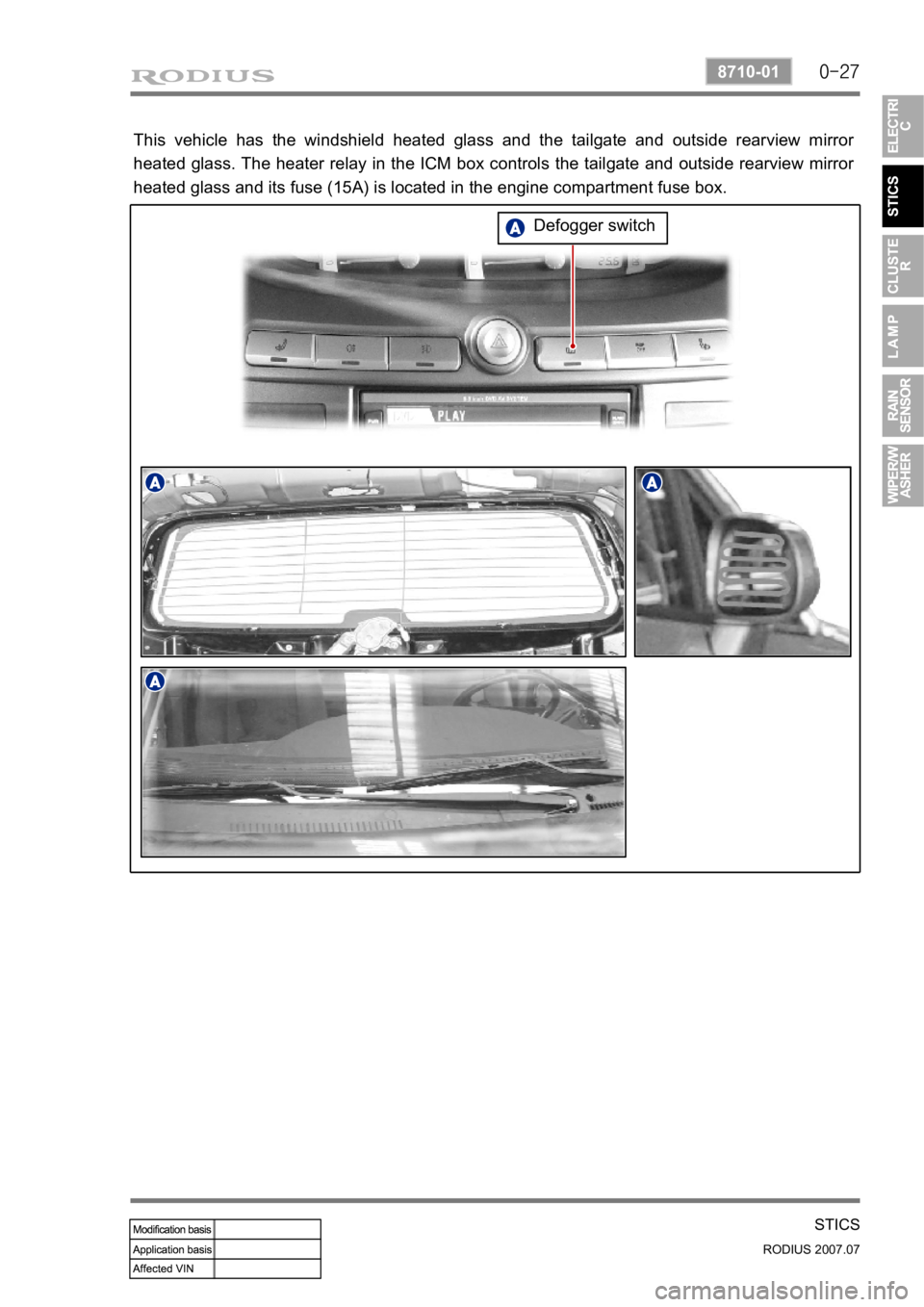
This vehicle has the windshield heated glass and the tailgate and outside rearview mirror
heated glass. The heater relay in the ICM box controls the tailgate and outside rearview mirro
r
heated glass and its fuse (15A) is located in the engine compartment fuse box.
Defogger switch
Page 212 of 444
0-39
STICS
RODIUS 2007.07
8710-01
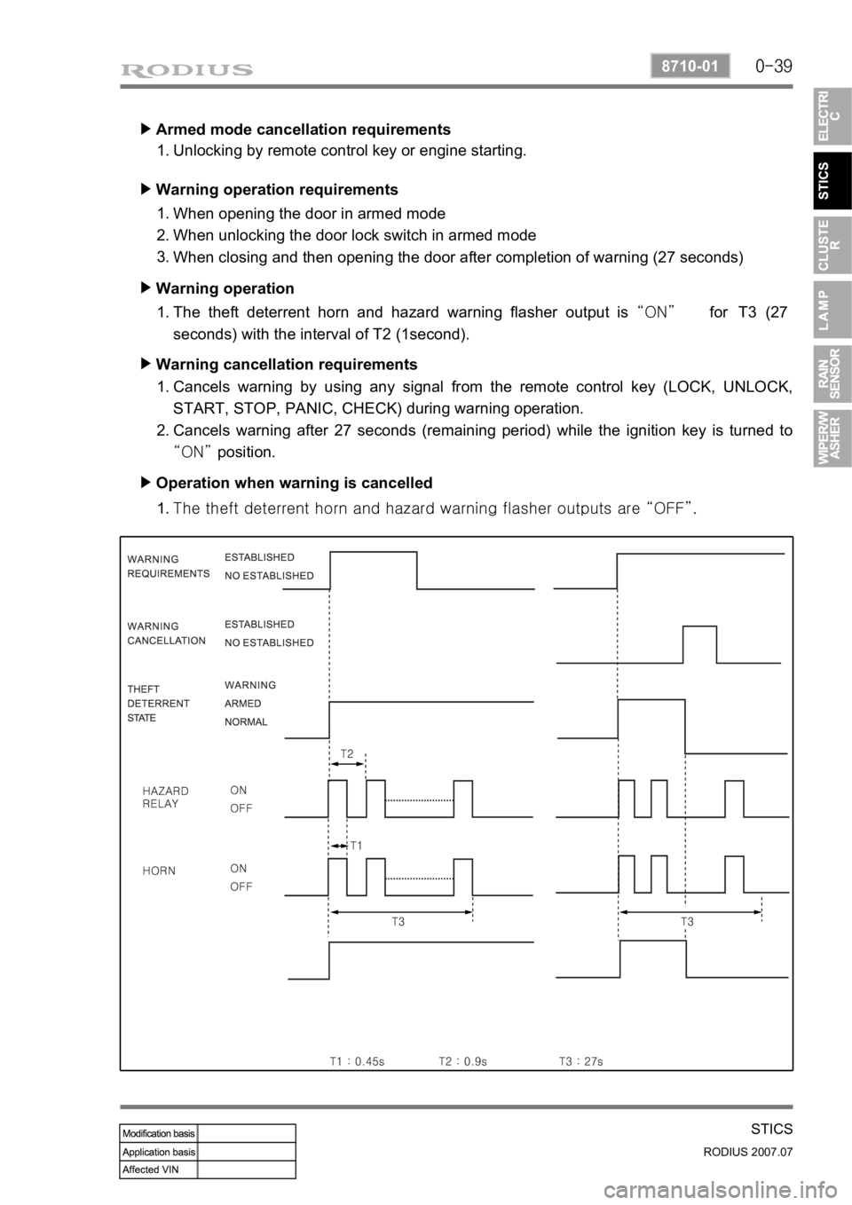
Armed mode cancellation requirements ▶
Unlocking by remote control key or engine starting. 1.
Warning operation requirements ▶
When opening the door in armed mode
When unlocking the door lock switch in armed mode
When closing and then opening the door after completion of warning (27 seconds) 1.
2.
3.
Warning operation ▶
The theft deterrent horn and hazard warning flasher output is “ON” for T3 (27
seconds) with the interval of T2 (1second). 1.
Warning cancellation requirements ▶
Cancels warning by using any signal from the remote control key (LOCK, UNLOCK,
START, STOP, PANIC, CHECK) during warning operation.
Cancels warning after 27 seconds (remaining period) while the ignition key is turned to
“ON” position. 1.
2.
Operation when warning is cancelled ▶
<007b008f008c0047009b008f008c008d009b0047008b008c009b008c00990099008c0095009b0047008f009600990095004700880095008b0047008f008800a100880099008b0047009e00880099009500900095008e0047008d00930088009a008f008c00
9900470096009c009b0097009c009b009a004700880099008c> “OFF”. 1.
Page 213 of 444

0-40
RODIUS 2007.07
8710-01
STICS
15) PANIC Warning
The PANIC warning output is “ON” (theft deterrent horn) when receiving the PANIC
signal from the remote control key (pressing PANIC button for less than 0.5 ~ 1.0 second).
The PANIC warning output is “OFF” when receiving any signal from the remote control
key during PANIC warning.
Followings are theft deterrent warnings: 1.
2.
3.
This function operates only in armed mode.
The system sends the current vehicle conditions (LOCK, engine running) when the PANIC
warning is turned off by the remote control key. 4.
5.The theft deterrent warning is canceled when receiving PANIC signal from the remote
control key during theft deterrent.
The theft deterrent warning output is “ON” when the theft deterrent conditions are
established during PANIC warning (PANIC output is “OFF”).
The PANIC warning output is “ON” when receiving the PANIC signal from the remote
control key in Armed Ready / Armed / Warning Completion / Relock Ready mode
(maintaining the theft deterrent mode). 1)
2)
3)
Page 216 of 444
0-4
RODIUS 2007.07
8010-10
CLUSTER
2. DESCRIPTIONS OF INDICATOR DISPLAY
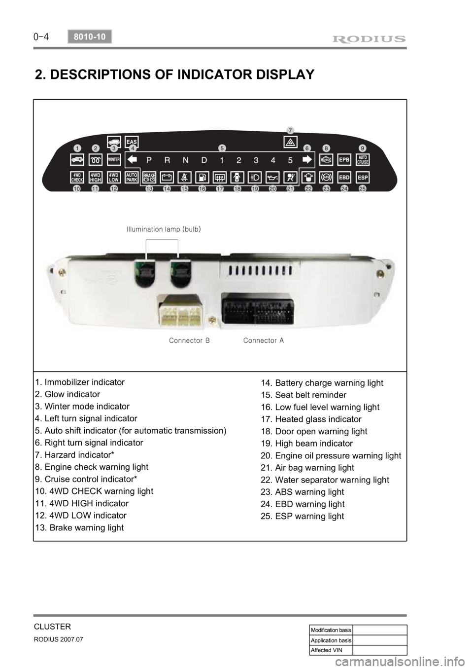
1. Immobilizer indicator
2. Glow indicator
3. Winter mode indicator
4. Left turn signal indicator
5. Auto shift indicator (for automatic transmission)
6. Right turn signal indicator
7. Harzard indicator*
8. Engine check warning light
9. Cruise control indicator*
10. 4WD CHECK warning light
11. 4WD HIGH indicator
12. 4WD LOW indicator
13. Brake warning light14. Battery charge warning light
15. Seat belt reminder
16. Low fuel level warning light
17. Heated glass indicator
18. Door open warning light
19. High beam indicator
20. Engine oil pressure warning light
21. Air bag warning light
22. Water separator warning light
23. ABS warning light
24. EBD warning light
25. ESP warning light
Page 220 of 444
0-8
RODIUS 2007.07
8010-10
CLUSTER
4. FUNCTION DESCRIPTION AND INSPECTION OF
METER
CLUSTER
1) Tachometer - Engine RPM Display
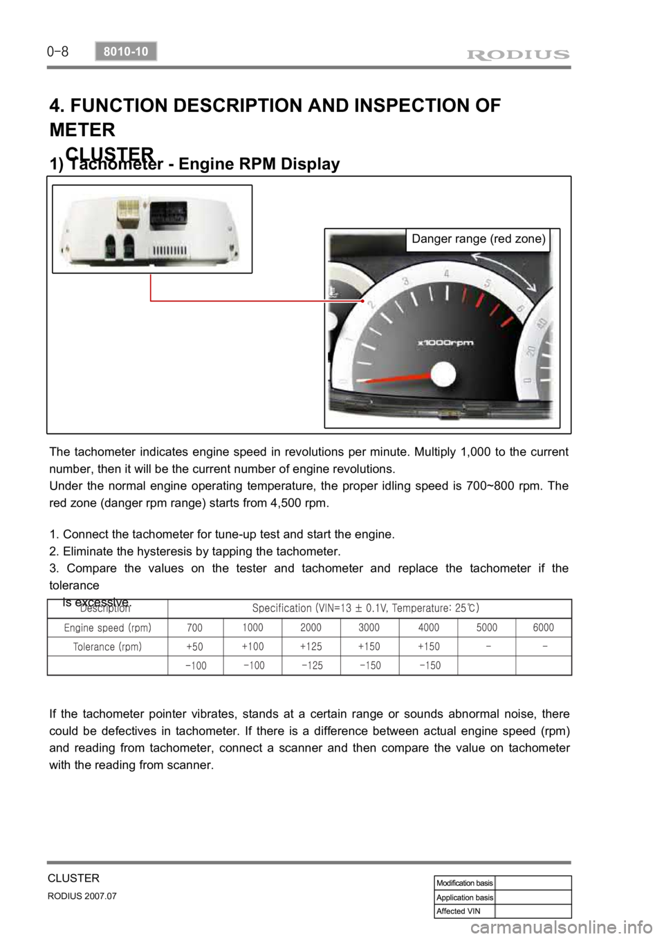
The tachometer indicates engine speed in revolutions per minute. Multiply 1,000 to the current
number, then it will be the current number of engine revolutions.
Under the normal engine operating temperature, the proper idling speed is 700~800 rpm. The
red zone (danger rpm range) starts from 4,500 rpm.
1. Connect the tachometer for tune-up test and start the engine.
2. Eliminate the hysteresis by tapping the tachometer.
3. Compare the values on the tester and tachometer and replace the tachometer if the
tolerance
is excessive.
If the tachometer pointer vibrates, stands at a certain range or sounds abnormal noise, there
could be defectives in tachometer. If there is a difference between actual engine speed (rpm)
and reading from tachometer, connect a scanner and then compare the value on tachomete
r
with the reading from scanner.
Danger range (red zone)
Page 235 of 444

0-12
RODIUS 2007.07
8310-01
LAMP
▶When Using a Screen Install a screen (2m X 1.5m) in front of the headlamps in vertical by 3m away and align the
center lines of the vehicle and the screen.
1.
Run the engine with approx. 2,000 rpm
and turn on the headlamp. At this
moment, the focus of the headlamp
should aim the “A” point.
2.
If the focus deviates the “A” point,
adjust the headlamp aiming by rotating
control levers (Up, Down, Left, Right) in
turn with a screwdriver.
3.(Unit: mm) (Unit: mm)