lock SSANGYONG RODIUS 2006 Service Manual
[x] Cancel search | Manufacturer: SSANGYONG, Model Year: 2006, Model line: RODIUS, Model: SSANGYONG RODIUS 2006Pages: 444, PDF Size: 56.32 MB
Page 5 of 444

0-5
GENERAL INFORMATION
undefined
0000-00
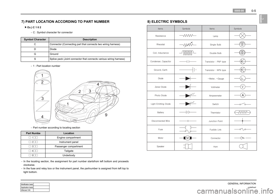
7) PART LOCATION ACCORDING TO PART NUMBER
Ex.) C 1 0 2 ▶
C : Symbol character for connector -
Symbol Character Description
C Connector (Connecting part that connects two wiring harness)
D Diode
G Ground
S Splice pack (Joint connector that connects various wiring harness)
1 : Part location number -
Part number according to locating section -
Part Numbe Location
□ 1□□Engine compartment
□ 2□□Instrument panel
□ 3□□Passenger compartment
□ 4□□Tailgate
□ 9□□Underbody
In the locating section, the assignment for part number startsfrom left bottom and proceeds
clockwise.
In the fuse and relay box or the instrument panel, the partnumber is assigned from left top to
light bottom. -
-
8) ELECTRIC SYMBOLS
Page 44 of 444

0-20undefined
8710-03
CIRCUIT3) DOOR LOCK, DEFOGGER
(1) CONNECTOR INFORMATION
Page 67 of 444

01-7
ENGINE INFORMATION
RODIUS 2007.07
0000-00
2. DESCRIPTION AND OPERATION
1) Cleanliness And Care
An automobile engine is a combination of many machined, honed, polished and lapped
surfaces with tolerances that are measured in the ten-thousanths of an inch. When any internal
engine parts are serviced, care and cleanliness are important. A liberal coating of enigne oil
should be applied to friction areas during assembly, to protect and lubricate the surfaces on
initial operation.
Proper cleaning and protection of machined surfaces and friction areas is part of the repai
r
procedure. This is considered standard shop practice even if not specifically stated.
Whenever valve train components are removed for service, they should be kept in order.
They should be installed in the same locations, and with the same mating surfaces, as when
they were removed. Battery cables should be disconnected before any major work is performed
on the engine. Failure to disconnect cables may result in damage to wire harness or othe
r
electrical parts.
2) On-Engine Service
Disconnect the negative battery cable before removing or installing any electrical unit, or
when a tool or equipment could easily come in contact with exposed electrical terminals.
Disconnecting this cable will help prevent personal injury and damage to the vehicle.
The ignition must also be in LOCK unless otherwise noted.
Notice Any time the air cleaner is removed, the intake opening -
Any time the air cleaner is removed, the intake opening should be covered. This will
protect against accidental entrance of foreign material, which could follow the intake
passage into the cylinder and cause extensive damage when the engine is started.g -
Page 85 of 444

07-6
RODIUS 2007.07
0000-00
COOLING SYSTEM
1. GENERAL DESCRIPTION
The cooling system maintains the engine temperature at an efficient level during all engine
operating conditions. When the engine is cold, the cooling system cools the engine slowly o
r
not at all. This slow cooling of the engine allows the engine to warm up quickly. The cooling
system includes a radiator and recovery subsystem, cooling fans, a thermostat and housing, a
water pump, and a water pump drive belt. The timing belt drives the water pump.
All
components must function properly for the cooling system to operation. The water pump draws
the coolant from the radiator.
The coolant then circulates through water jackets in the engine block, the intake manifold, and
the cylinder head. When the coolant reaches the operating temperature of the thermostat, the
thermostat opens. The coolant then goes back to the radiator where it cools. This system
directs some coolant through the hoses to the heat core. This provides for heating and
defrosting. The coolant reservoir is connected to the radiator to recover the coolant displaced
by expansion from the high temperatures. The coolant reservoir maintains the correct coolant
level. The cooling system for this vehicle has no radiator cap or filler neck. The coolant is
added to the cooling system through the coolant reservoir.
Page 97 of 444

0-3
SPECIAL SERVICE TOOLS
RODIUS 2007.07
0000-00
0000-00SPECIAL SERVICE TOOLS
1. ENGINE ASSEMBLY
Injector Puller
Y99220072BGlow Plug Wrench
Y99220132BFuel Pipe WrenchSealing Caps
665 995 5844
Valve
Remover/Installer
Y99220082BPulley Lock/Wrench
Y99220052BEngine Lock
602 589 00 40 00
Injector Copper
Washer Puller
Y99220022B
(1) D20DT Engine
1) COMPONENTS AND SPECIAL TOOLS
Page 98 of 444

0-4
RODIUS 2007.07
0000-00
SPECIAL SERVICE TOOLS
Injector Puller Y99220072B Glow Plug Wrench
Y99220132B Fuel Pipe Wrench Sealing Caps
665 995 5844
Injector Copper Washer Puller
Y99220022B
Valve
Remover/Installer
Y99220082B Pulley Lock/Wrench
Y99220052B HP Pump Lock
Y99220102B
Engine Lock
602 589 00 40 00
HP Pump Bearing Puller
Y99220032B
(2) D27DT Engine
Page 146 of 444

0-3
ENGINE INTAKE SYSTEM
RODIUS 2007.07
0000-00
2321-01ENGINE INTAKE SYSTEM
1. INTAKE SYSTEM LAYOUT
The intake system for the D27DTP (POWER UP) engine is equipped with the throttle body that
has a flap to block the air coming to the engine when the engine is switched off. Therefore, the
structure of the intake manifold has been changed.
Also, the improved HFM sensor (from HFM5.0 to HFM6.0) has been installed to control the
intake air precisely so that the NOx in the exhaust gas can be decreased.
Page 159 of 444

0-30000-00
1. COMPARISON IN COOLING SYSTEM FOR EACH ENGINE
For the D27DTP (POWER UP) engine, the cooling system is equipped with E-EGR cooler and the water
pump which its capacity is improved according to the additional coolant line in the cylinder block. For the
D27DT engine, the cooling system uses the fan clutch.
▶Cooling System for D27DTP (POWER UP) Engine
Page 178 of 444

0-5
STICS
RODIUS 2007.07
8710-01
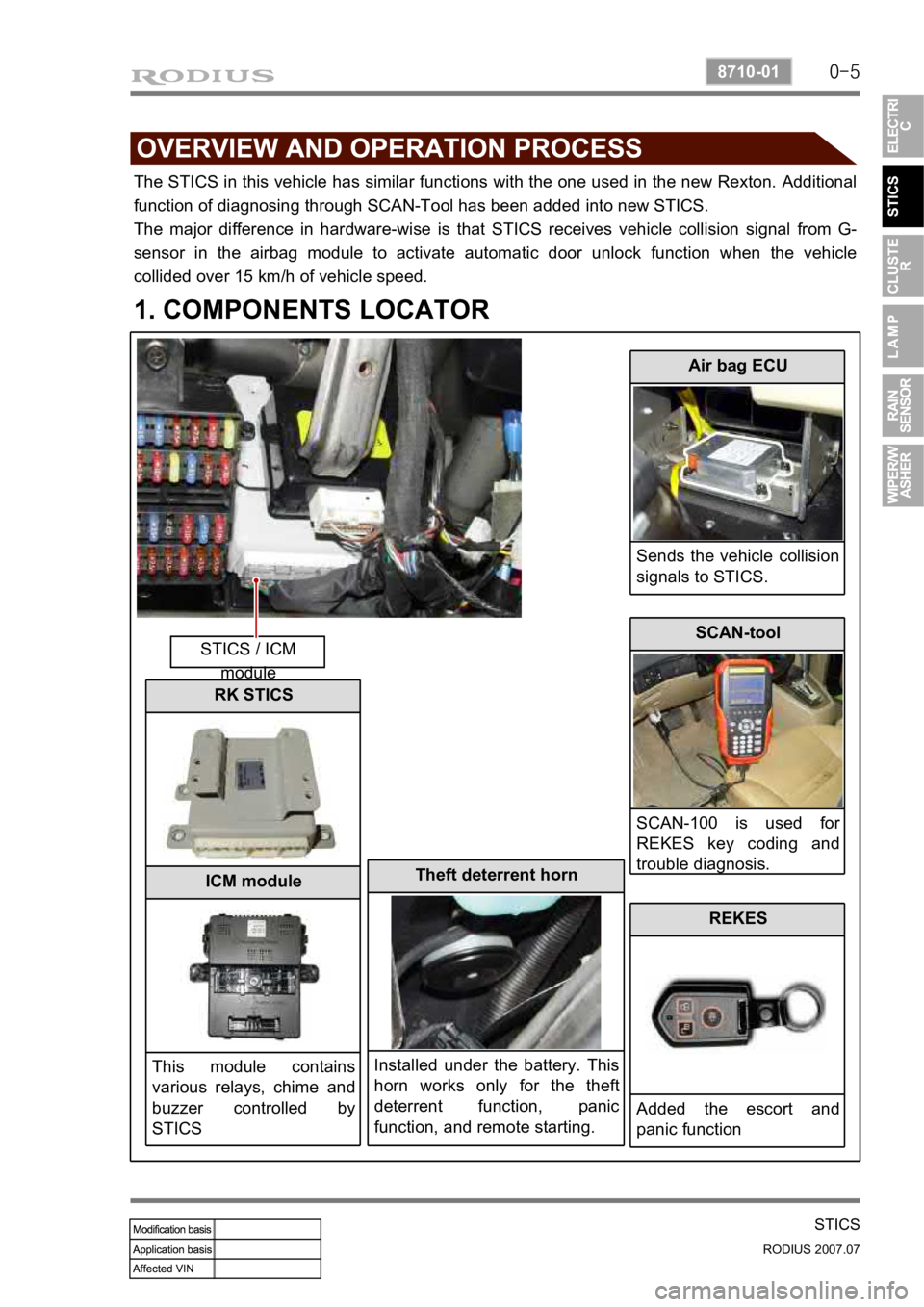
The STICS in this vehicle has similar functions with the one used in the new Rexton. Additional
function of diagnosing through SCAN-Tool has been added into new STICS.
The major difference in hardware-wise is that STICS receives vehicle collision signal from G-
sensor in the airbag module to activate automatic door unlock function when the vehicle
collided over 15 km/h of vehicle speed.
1. COMPONENTS LOCATOR
STICS / ICM module
Air bag ECU
Sends the vehicle collision
signals to STICS.
Theft deterrent horn
Installed under the battery. This
horn works only for the theft
deterrent function, panic
function, and remote starting.
SCAN-tool
SCAN-100 is used fo
r
REKES key coding and
trouble diagnosis.
REKES
Added the escort and
panic function
RK STICS
ICM module
This module contains
various relays, chime and
buzzer controlled by
STICS
Page 189 of 444

0-16
RODIUS 2007.07
8710-01
STICS
2) Ignition Key Reminder
(1) Key Reminder Warning
The chime buzzer output in the ICM box continues when opening the driver’s door
while the ignition key is inserted into ignition switch.
When removing the ignition key or closing the driver’s door during chime buzzer output,
the output turns off.
This function is not available when the ignition switch is “ON”. 1.
2.
3.
(2) Key Reminder
This function does not work if the vehicle speed is over 3 km/h.
The system outputs “UNLOCK” for 5 seconds (T2) from 0.5 seconds after the driver’s
door is opened and the door lock switch is changed to “LOCK” (while the ignition key
is in ignition switch).
The system outputs “UNLOCK” for 5 seconds (T2) when the door lock switch is
changed to “LOCK” from “UNLOCK” and the driver’s door is closed within 0.5
seconds (T1) (while the ignition key is in ignition switch). 1.
2.
3.
Operating conditions for (*1) and (*2)
<004f00510058005000610047006b00990090009d008c009902c5009a0047008b00960096009900470090009a004700960097008c0095008c008b004700880095008b0047008b00990090009d008c009902c5009a0047008b00960096009900470093009600
8a00920047009a009e0090009b008a008f00470090009a0047>turned to LOCK
<004f0051005900500061004700770088009a009a008c0095008e008c009902c5009a0047008b00960096009900470090009a004700960097008c0095008c008b004700880095008b004700970088009a009a008c0095008e008c009902c5009a0047008b00
9600960099004700930096008a00920047009a009e0090009b>ch is turned to LOCK -