power steering SSANGYONG RODIUS 2006 Service Manual
[x] Cancel search | Manufacturer: SSANGYONG, Model Year: 2006, Model line: RODIUS, Model: SSANGYONG RODIUS 2006Pages: 444, PDF Size: 56.32 MB
Page 130 of 444

0-26
RODIUS 2007.07
0000-00
ENGINE GENERAL
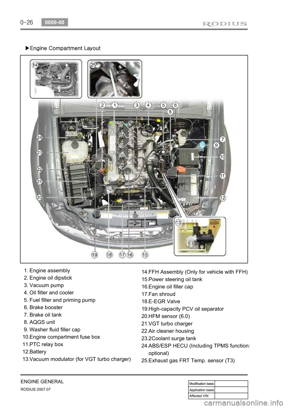
▶Engine Compartment Layout
Engine assembly
Engine oil dipstick
Vacuum pump
Oil filter and cooler
Fuel filter and priming pump
Brake booster
Brake oil tank
AQGS unit
Washer fluid filler cap
Engine compartment fuse box
PTC relay box
Battery
Vacuum modulator (for VGT turbo charger) 1.
2.
3.
4.
5.
6.
7.
8.
9.
10.
11.
12.
13.FFH Assembly (Only for vehicle with FFH)
Power steering oil tank
Engine oil filler cap
Fan shroud
E-EGR Valve
High-capacity PCV oil separator
HFM sensor (6.0)
VGT turbo charger
Air cleaner housing
2Coolant surge tank
ABS/ESP HECU (Including TPMS function:
optional)
Exhaust gas FRT Temp. sensor (T3) 14.
15.
16.
17.
18.
19.
20.
21.
22.
23.
24.
25.
Page 306 of 444

0-7
ESP SYSTEM
RODIUS 2007.07
4892-01
Over steeringOversteering is when the steering wheel is
steered to a certain angle during driving and
the rear tires slip outward losing traction.
When compared with under steering
vehicles, the controlling of the vehicle is
difficult during cornering and the vehicle can
spin due to rear wheel moment when the
rear tires lose traction and the vehicle speed
increases.
ESP controls during oversteering
The ESP system recognizes the directional
angle with the steering wheel angle senso
r
and senses the slipping route that occurs
towards the vehicle cornering direction
during oversteering with the yaw rate senso
r
and the lateral sensor. Then the ESP system
applies the brake at the front outer wheel to
compensate the yaw moment value.
In this way, the vehicle does not lose its
driving direction and the driver can steer the
vehicle as he or she intends.
2) ESP Control
The ESP system includes the ABS/EBD and ASR systems allowing the system to be able to
operate depending to the vehicle driving conditions. For example, when the brakes are applied
during cornering at the speed of 100 km/h, the ABS system will operate at the same time the
ASR or ABD systems operate to reduce the power from the slipping wheel. And when yaw rate
sensor detects the rate exceeding 4¡Æ/seconds, the ESP system is activated to apply the
brake force to the corresponding wheel to compensate the yaw moment with the vehicle
stability control function. When various systems operate simultaneously under a certain
situation, there may be vehicle control problems due to internal malfunction of a system o
r
simultaneous operations. In order to compensate to this problem, the ESP system sets the
priority among systems. The system operates in the order of TCS (ASR or ABD), ESP and
ABS. The order may be changed depending on the vehicle driving situations and driving
conditions. As the single-track vehicle model used for the calculations is only valid for a vehicle
moving forward, ESP intervention never takes place during backup.
Page 341 of 444

0-3
POWER STEERING SYSTEM
RODIUS 2007.07
4610-00
4610-00POWER STEERING SYSTEM
1. SPECIFICATION
Page 342 of 444

0-4
RODIUS 2007.07
4610-00
POWER STEERING SYSTEM
2. TIGHTENING TORQUE
3. SPECIAL TOOLS AND EQUIPMENT
Page 343 of 444

0-5
POWER STEERING SYSTEM
RODIUS 2007.07
4610-00
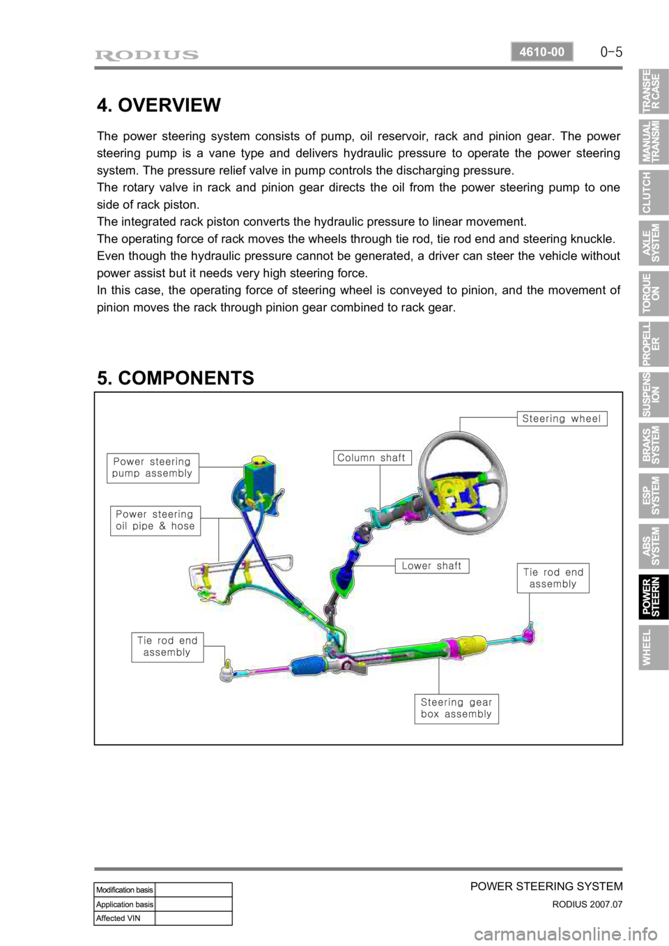
4. OVERVIEW
The power steering system consists of pump, oil reservoir, rack and pinion gear. The power
steering pump is a vane type and delivers hydraulic pressure to operate the power steering
system. The pressure relief valve in pump controls the discharging pressure.
The rotary valve in rack and pinion gear directs the oil from the power steering pump to one
side of rack piston.
The integrated rack piston converts the hydraulic pressure to linear movement.
The operating force of rack moves the wheels through tie rod, tie rod end and steering knuckle.
Even though the hydraulic pressure cannot be generated, a driver can steer the vehicle without
power assist but it needs very high steering force.
In this case, the operating force of steering wheel is conveyed to pinion, and the movement o
f
pinion moves the rack through pinion gear combined to rack gear.
5. COMPONENTS
Page 344 of 444

0-6
RODIUS 2007.07
4610-00
POWER STEERING SYSTEM
1. COMPONENTS OF POWER STEERING ASSEMBLY
Page 345 of 444

0-7
POWER STEERING SYSTEM
RODIUS 2007.07
4610-00
2. POWER STEERING GEAR BOX ASSEMBLY
The power steering gear consists of power cylinder and control valve.
The power cylinder has cylinder, piston and piston rod. The control valve directs the oil to one
end face of the piston to enhance the steering force.
The control valve controls the directions and operations of power cylinder.
Additionally, the safety check valve is installed so that the system can be operated manually
when the system is defective.
Page 346 of 444

0-8
RODIUS 2007.07
4610-00
POWER STEERING SYSTEM
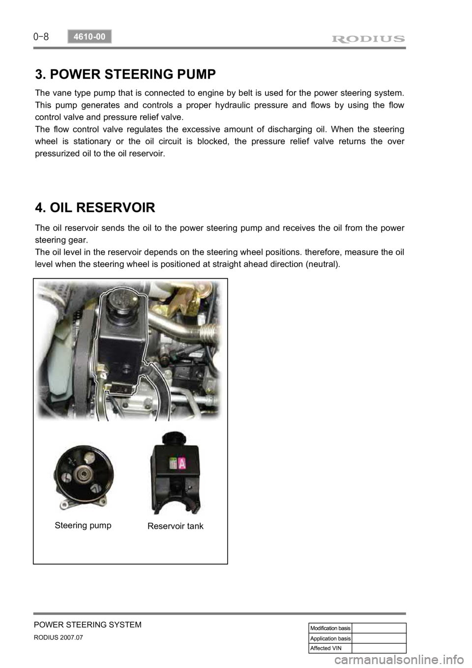
3. POWER STEERING PUMP
The vane type pump that is connected to engine by belt is used for the power steering system.
This pump generates and controls a proper hydraulic pressure and flows by using the flow
control valve and pressure relief valve.
The flow control valve regulates the excessive amount of discharging oil. When the steering
wheel is stationary or the oil circuit is blocked, the pressure relief valve returns the ove
r
pressurized oil to the oil reservoir.
4. OIL RESERVOIR
The oil reservoir sends the oil to the power steering pump and receives the oil from the power
steering gear.
The oil level in the reservoir depends on the steering wheel positions. therefore, measure the oil
level when the steering wheel is positioned at straight ahead direction (neutral).
Steering pump Reservoir tank