air filter SSANGYONG RODIUS 2007 Service Manual
[x] Cancel search | Manufacturer: SSANGYONG, Model Year: 2007, Model line: RODIUS, Model: SSANGYONG RODIUS 2007Pages: 465, PDF Size: 56.32 MB
Page 122 of 465

0-26
RODIUS 2006.09
0000-00
ENGINE GENERAL
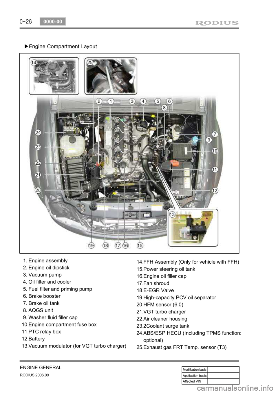
▶Engine Compartment Layout
Engine assembly
Engine oil dipstick
Vacuum pump
Oil filter and cooler
Fuel filter and priming pump
Brake booster
Brake oil tank
AQGS unit
Washer fluid filler cap
Engine compartment fuse box
PTC relay box
Battery
Vacuum modulator (for VGT turbo charger) 1.
2.
3.
4.
5.
6.
7.
8.
9.
10.
11.
12.
13.FFH Assembly (Only for vehicle with FFH)
Power steering oil tank
Engine oil filler cap
Fan shroud
E-EGR Valve
High-capacity PCV oil separator
HFM sensor (6.0)
VGT turbo charger
Air cleaner housing
2Coolant surge tank
ABS/ESP HECU (Including TPMS function:
optional)
Exhaust gas FRT Temp. sensor (T3) 14.
15.
16.
17.
18.
19.
20.
21.
22.
23.
24.
25.
Page 146 of 465

0-9
CDEF(Catalytic Disel Particulate Filter)
RODIUS 2006.09
0000-00
2) Sytem Composition for Soot Combustion
When the engine is running in low load range, the temperature of exhaust gas is decreased as
the amount of fuel supplied is decreased. To burnt the soot filtered in the CDPF, the control
system should be installed to check the operating range and increase the temperature o
f
exhaust gas by controlling the amount of fuel supplied and and intake air.
Two temperature sensors and one differential pressure sensor monitor the CDPF's operating
range. According to theses sensors' information, the throttle flap decreases the intake ai
r
entered to the throttle body. Also, the fuel injection pattern is added to increase the temperature
of exhaust gas for soot combustion.
There are two fuel injection patterns (pilot injection and main injection). As the CDPF is
installed, the post injection pattern is added.
3) Post Injection and Air Mass Control
When the differential pressure sensor detects the pressure difference between the front and the
rear side of CDPF, the sensor sends signal indicating the soot is acumulated and the post
injection is performed to raise the temperature of exhaust gas. The amount of fuel injected is
determined according to the temperature of exhaust gas detected by the rear temperature
<009a008c0095009a00960099005500470070008d0047009b008f008c0047009b008c00940097008c00990088009b009c0099008c00470090009a00470089008c00930096009e0047005d0057005700b6006a00530047009b008f008c004700880094009600
9c0095009b00470096008d0047008d009c008c009300470090>njected is increased to
<009900880090009a008c0047009b008f008c0047009b008c00940097008c00990088009b009c0099008c005500470070008d0047009b008f008c0047009b008c00940097008c00990088009b009c0099008c00470090009a00470096009d008c0099004700
5d0057005700b6006a00530047009b008f008c004700880094>ount of fuel injected is
decreased or not controlled.
When the engine is running in low load range, the amount of post injection and the amount of
intake air are controlled.
It is to raise the temperature by increasing the amount of fuel while decreasing the amount of
intake air.
Page 321 of 465

0-7
BRAKS SYSTEM
RODIUS 2006.09
4830-01
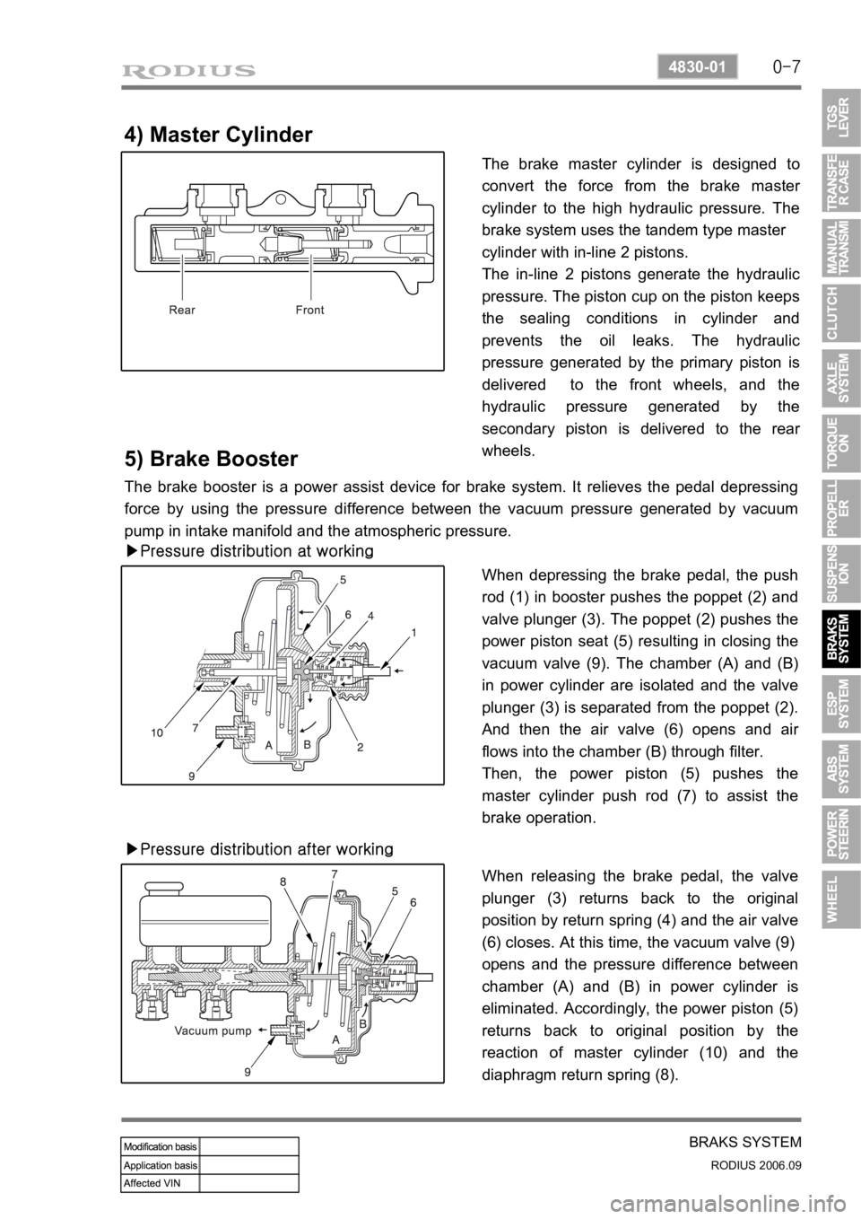
4) Master Cylinder
The brake master cylinder is designed to
convert the force from the brake maste
r
cylinder to the high hydraulic pressure. The
brake system uses the tandem type master
cylinder with in-line 2 pistons.
The in-line 2 pistons generate the hydraulic
pressure. The piston cup on the piston keeps
the sealing conditions in cylinder and
prevents the oil leaks. The hydraulic
pressure generated by the primary piston is
delivered to the front wheels, and the
hydraulic pressure generated by the
secondary piston is delivered to the rea
r
wheels.
5) Brake Booster
The brake booster is a power assist device for brake system. It relieves the pedal depressing
force by using the pressure difference between the vacuum pressure generated by vacuum
pump in intake manifold and the atmospheric pressure.
▶Pressure distribution at working
When depressing the brake pedal, the push
rod (1) in booster pushes the poppet (2) and
valve plunger (3). The poppet (2) pushes the
power piston seat (5) resulting in closing the
vacuum valve (9). The chamber (A) and (B)
in power cylinder are isolated and the valve
plunger (3) is separated from the poppet (2).
And then the air valve (6) opens and ai
r
flows into the chamber (B) through filter.
Then, the power piston (5) pushes the
master cylinder push rod (7) to assist the
brake operation.
▶Pressure distribution after working
When releasing the brake pedal, the valve
plunger (3) returns back to the original
position by return spring (4) and the air valve
(6) closes. At this time, the vacuum valve (9)
opens and the pressure difference between
chamber (A) and (B) in power cylinder is
eliminated. Accordingly, the power piston (5)
returns back to original position by the
reaction of master cylinder (10) and the
diaphragm return spring (8).
Page 382 of 465

0-10
RODIUS 2006.09
6810-20
AIR CONDITIONING SYSTEM
2. AIR CONDITIONER MODULE WIRING AND LAYOUT
1) Front Air Conditioner Module
Wiring layout
Components
Air source selection
door actuatorAir conditioner filterEvaporator
Blower
motor
Blower high
speed relay
Heater core