alarm SSANGYONG RODIUS 2007 Service Manual
[x] Cancel search | Manufacturer: SSANGYONG, Model Year: 2007, Model line: RODIUS, Model: SSANGYONG RODIUS 2007Pages: 465, PDF Size: 56.32 MB
Page 211 of 465
0-38
RODIUS 2006.09
8710-01
STICS
14) Theft Deterrent
(1) Description of Burglar Alarm Function
Description of Burglar Alarm Function ▶
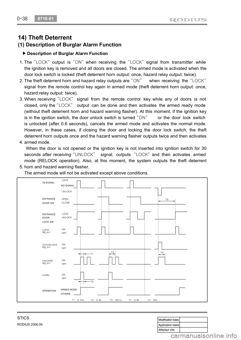
The “LOCK” output is “ON” when receiving the “LOCK” signal from transmitter while
the ignition key is removed and all doors are closed. The armed mode is activated when the
door lock switch is locked (theft deterrent horn output: once, hazard relay output: twice).
The theft deterrent horn and hazard relay outputs are “ON” when receiving the “LOCK”
signal from the remote control key again in armed mode (theft deterrent horn output: once,
hazard relay output: twice).
When receiving “LOCK” signal from the remote control key while any of doors is not
closed, only the “LOCK” output can be done and then activates the armed ready mode
(without theft deterrent horn and hazard warning flasher). At this moment, if the ignition key
is in the ignition switch, the door unlock switch is turned “ON” or the door lock switch
is unlocked (after 0.6 seconds), cancels the armed mode and activates the normal mode.
However, in these cases, if closing the door and locking the door lock switch, the theft
deterrent horn outputs once and the hazard warning flasher outputs twice and then activates
armed mode.
When the door is not opened or the ignition key is not inserted into ignition switch for 30
seconds after receiving “UNLOCK” signal, outputs “LOCK” and then activates armed
mode (RELOCK operation). Also, at this moment, the system outputs the theft deterrent
horn and hazard warning flasher.
The armed mode will not be activated except above conditions.
Ex) The armed mode will not be activated when the door is locked by the ignition key. 1.
2.
3.
4.
5.
Page 252 of 465
0-3
PARKING AID SYSTEM
RODIUS 2006.09
8790-04
8790-04PARKING ASSISTANCE SYSTEM
1. COMPONENT SPECIFICATIONS OF PARKING AID
SYSTEM
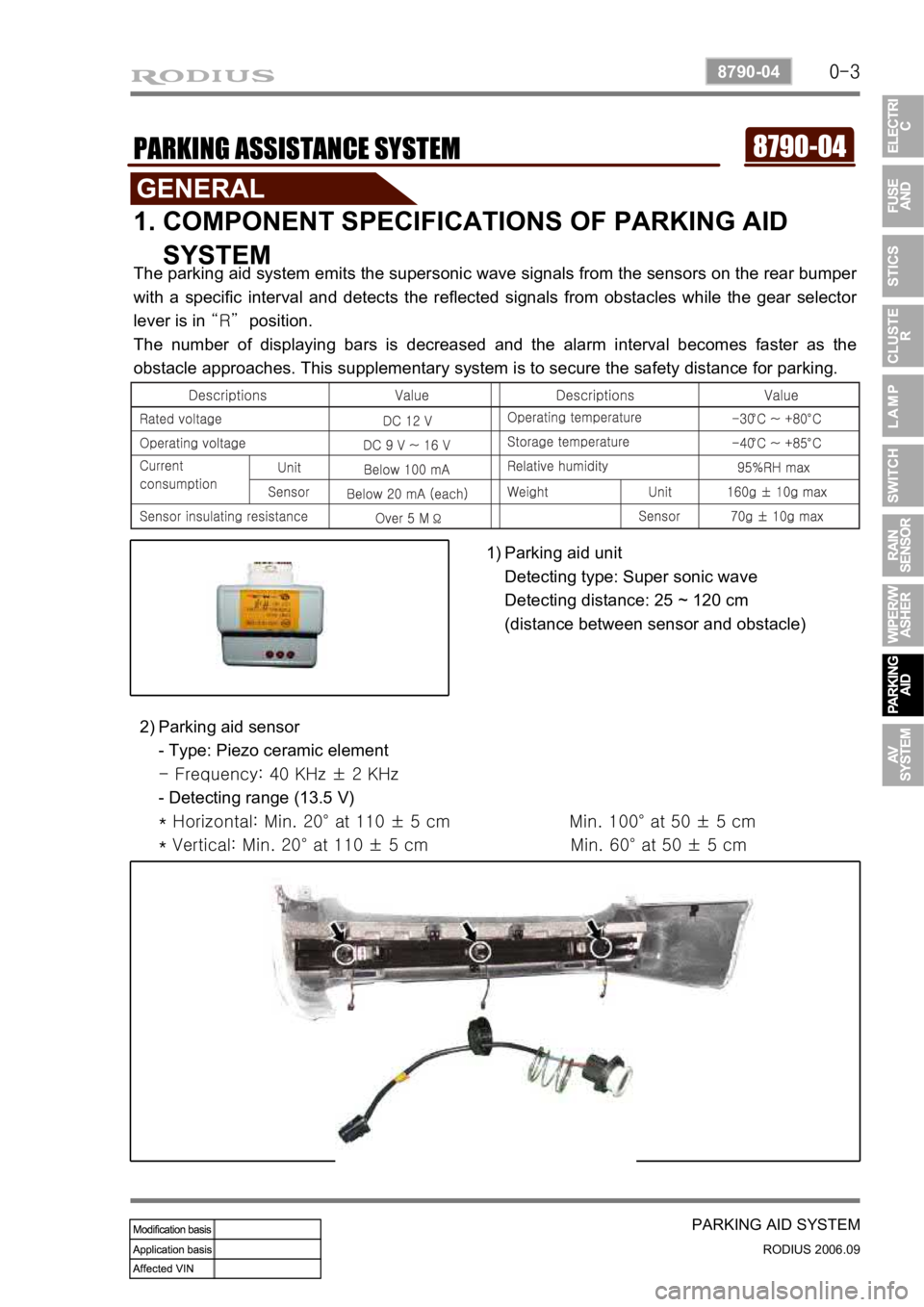
The parking aid system emits the supersonic wave signals from the sensors on the rear bumper
with a specific interval and detects the reflected signals from obstacles while the gear selecto
r
lever is in “R” position.
The number of displaying bars is decreased and the alarm interval becomes faster as the
obstacle approaches. This supplementary system is to secure the safety distance for parking.
Parking aid unit
Detecting type: Super sonic wave
Detecting distance: 25 ~ 120 cm
(distance between sensor and obstacle)
1)
Parking aid sensor
- Type: Piezo ceramic element
- Frequency: 40 KHz ± 2 KHz
- Detecting range (13.5 V)
* Horizontal: Min. 20° at 110 ± 5 cm Min. 1 00° at 50 ± 5 cm
* Vertical: Min. 20° at 110 ± 5 cm Min. 60° at 50 ± 5 cm
2)
Page 254 of 465
0-5
PARKING AID SYSTEM
RODIUS 2006.09
8790-04
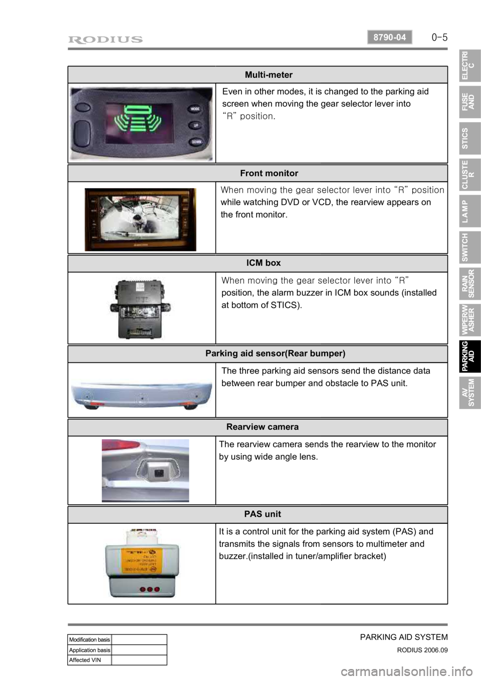
Multi-meter
Front monitor ICM box
Even in other modes, it is changed to the parking aid
screen when moving the gear selector lever into
“R” position.
When moving the gear selector lever into “R”
position
while watching DVD or VCD, the rearview appears on
the front monitor.
When moving the gear selector lever into “R”
position, the alarm buzzer in ICM box sounds (installed
at bottom of STICS).
Parking aid sensor(Rear bumper)
The three parking aid sensors send the distance data
between rear bumper and obstacle to PAS unit.
Rearview camera
The rearview camera sends the rearview to the monitor
by using wide angle lens.
PAS unit
It is a control unit for the parking aid system (PAS) and
transmits the signals from sensors to multimeter and
buzzer.(installed in tuner/amplifier bracket)
Page 257 of 465
0-8
RODIUS 2006.09
8790-04
PARKING AID SYSTEM
3. OPERATIONS OF PARKING AID SYSTEM(PAS)
1) Alarm interval
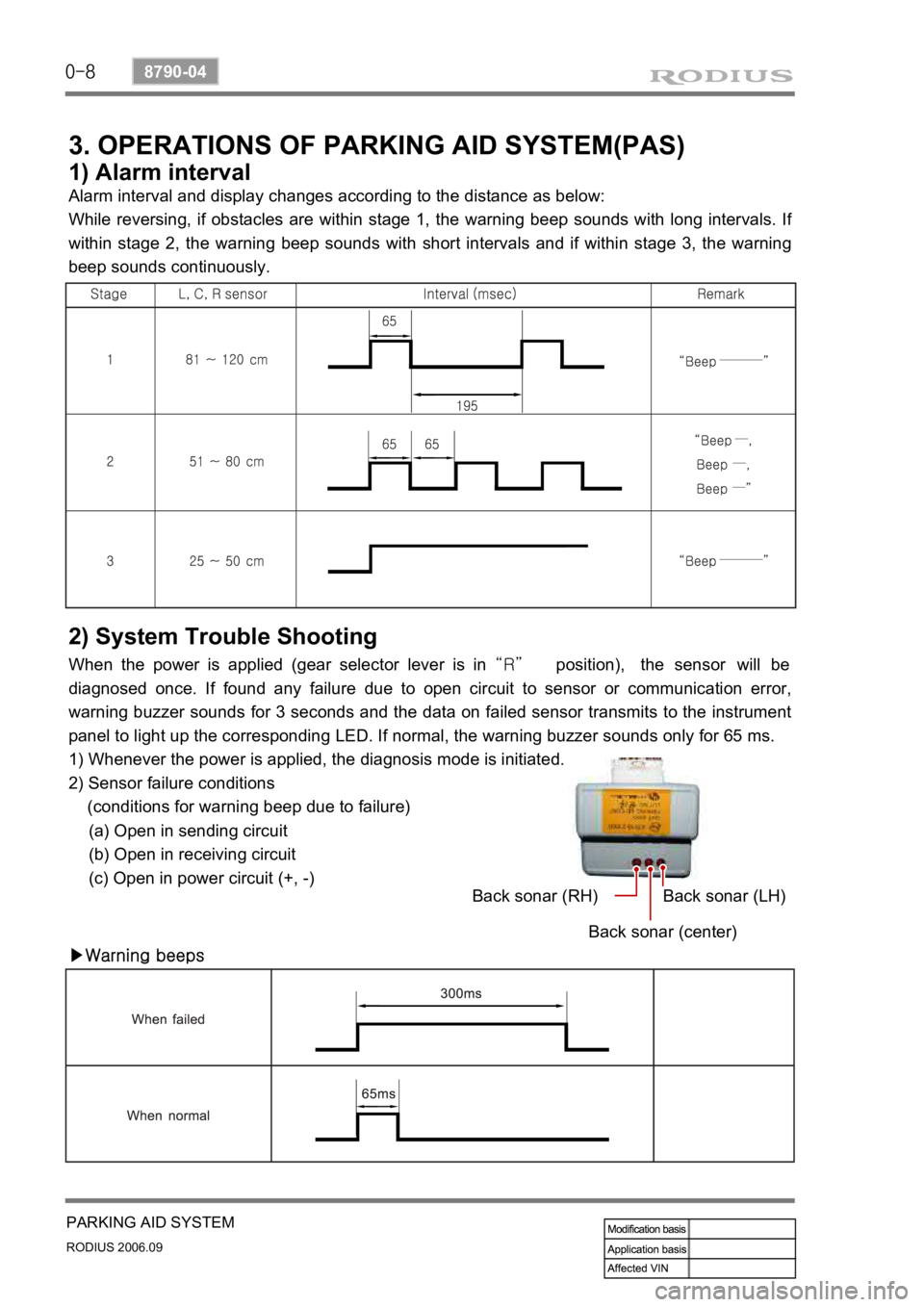
Alarm interval and display changes according to the distance as below:
While reversing, if obstacles are within stage 1, the warning beep sounds with long intervals. I
f
within stage 2, the warning beep sounds with short intervals and if within stage 3, the warning
beep sounds continuously.
2) System Trouble Shooting
When the power is applied (gear selector lever is in “R” position), the sensor will be
diagnosed once. If found any failure due to open circuit to sensor or communication error,
warning buzzer sounds for 3 seconds and the data on failed sensor transmits to the instrument
panel to light up the corresponding LED. If normal, the warning buzzer sounds only for 65 ms.
1) Whenever the power is applied, the diagnosis mode is initiated.
2) Sensor failure conditions
(conditions for warning beep due to failure)
(a) Open in sending circuit
(b) Open in receiving circuit
(c) Open in power circuit (+, -)
▶Warning beepsBack sonar (RH)
Back sonar (center)Back sonar (LH)
Page 273 of 465
0-4
RODIUS 2006.09
3410-01
TRANSFER CASE
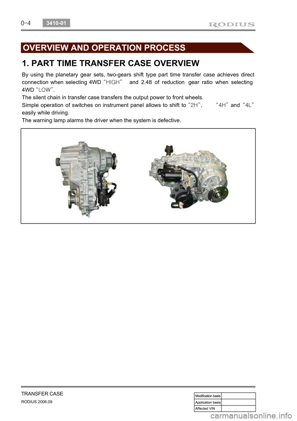
1. PART TIME TRANSFER CASE OVERVIEW
By using the planetary gear sets, two-gears shift type part time transfer case achieves direct
connection when selecting 4WD “HIGH” and 2.48 of reduction gear ratio when selecting
4WD “LOW”.
The silent chain in transfer case transfers the output power to front wheels.
Simple operation of switches on instrument panel allows to shift to “2H”, “4H” and “4L”
easily while driving.
The warning lamp alarms the driver when the system is defective.