belt SSANGYONG RODIUS 2007 Service Manual
[x] Cancel search | Manufacturer: SSANGYONG, Model Year: 2007, Model line: RODIUS, Model: SSANGYONG RODIUS 2007Pages: 465, PDF Size: 56.32 MB
Page 42 of 465

0-17
CIRCUIT
RODIUS 2006.09
8010-01
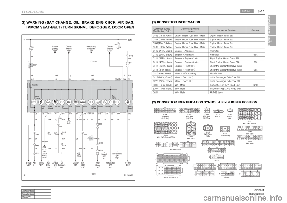
3)
(1) CONNECTOR INFORMATION
(2) CONNECTOR IDENTIFICATION SYMBOL & PIN NUMBER POSITION
WARNING (BAT CHANGE, OIL, BRAKE ENG CHCK, AIR BAG,
IMMOM SEAT-BELT) TURN SIGNAL, DEFOGGER, DOOR OPEN
Page 77 of 465

07-6
RODIUS 2006.09
0000-00
COOLING SYSTEM
1. GENERAL DESCRIPTION
The cooling system maintains the engine temperature at an efficient level during all engine
operating conditions. When the engine is cold, the cooling system cools the engine slowly o
r
not at all. This slow cooling of the engine allows the engine to warm up quickly. The cooling
system includes a radiator and recovery subsystem, cooling fans, a thermostat and housing, a
water pump, and a water pump drive belt. The timing belt drives the water pump.
All
components must function properly for the cooling system to operation. The water pump draws
the coolant from the radiator.
The coolant then circulates through water jackets in the engine block, the intake manifold, and
the cylinder head. When the coolant reaches the operating temperature of the thermostat, the
thermostat opens. The coolant then goes back to the radiator where it cools. This system
directs some coolant through the hoses to the heat core. This provides for heating and
defrosting. The coolant reservoir is connected to the radiator to recover the coolant displaced
by expansion from the high temperatures. The coolant reservoir maintains the correct coolant
level. The cooling system for this vehicle has no radiator cap or filler neck. The coolant is
added to the cooling system through the coolant reservoir.
Page 193 of 465

0-20
RODIUS 2006.09
8710-01
STICS
5) Seat Belt Warning
The seat belt warning light comes on and the chime buzzer in the ICM box sounds for 6
<009a008c008a00960095008b009a0047009e008f008c00950047009b009c0099009500900095008e0047009b008f008c00470090008e00950090009b00900096009500470092008c00a00047009b0096004702c80076007502c90047008d00990096009400
4702c80076006d006d02c9005500470070008d0047009b008f>e seat belt is fastened
<0089008c008d00960099008c0047009b009c0099009500900095008e0047009b008f008c00470090008e00950090009b00900096009500470092008c00a00047009b0096004702c80076007502c9004700970096009a0090009b0090009600950053004700
9b008f008c0047009e00880099009500900095008e00470093>ight in the indicator
display blinks for 6 seconds, however, the chime buzzer does not sound.
The seat belt warning light goes off and the chime buzzer in the ICM box stops when turning
the ignition switch to “OFF” position.
The chime buzzer stops and the seat belt warning light stays on for the specified duration (6
seconds) when fastening the seat belt during the warning operation.
The seat belt warning light comes on and the chime buzzer sounds for 6 seconds again
when unfastening the seat belt during fastening operation. 1.
2.
3.
4.
Page 216 of 465

0-4
RODIUS 2006.09
8010-10
CLUSTER
2. DESCRIPTIONS OF INDICATOR DISPLAY
1. Immobilizer indicator
2. Glow indicator
3. Winter mode indicator
4. Left turn signal indicator
5. Auto shift indicator (for automatic transmission)
6. Right turn signal indicator
7. Harzard indicator*
8. Engine check warning light
9. Cruise control indicator*
10. 4WD CHECK warning light
11. 4WD HIGH indicator
12. 4WD LOW indicator
13. Brake warning light14. Battery charge warning light
15. Seat belt reminder
16. Low fuel level warning light
17. Heated glass indicator
18. Door open warning light
19. High beam indicator
20. Engine oil pressure warning light
21. Air bag warning light
22. Water separator warning light
23. ABS warning light
24. EBD warning light
25. ESP warning light
Page 367 of 465

0-8
RODIUS 2006.09
4610-00
POWER STEERING SYSTEM
3. POWER STEERING PUMP
The vane type pump that is connected to engine by belt is used for the power steering system.
This pump generates and controls a proper hydraulic pressure and flows by using the flow
control valve and pressure relief valve.
The flow control valve regulates the excessive amount of discharging oil. When the steering
wheel is stationary or the oil circuit is blocked, the pressure relief valve returns the ove
r
pressurized oil to the oil reservoir.
4. OIL RESERVOIR
The oil reservoir sends the oil to the power steering pump and receives the oil from the power
steering gear.
The oil level in the reservoir depends on the steering wheel positions. therefore, measure the oil
level when the steering wheel is positioned at straight ahead direction (neutral).
Steering pump Reservoir tank
Page 369 of 465

0-4
RODIUS 2006.09
4710-09
WHEEL
1. OVERVIEW OF WHEEL & TIRE
1) Tire And wheel Balancing
There are two types of the tire and wheel balancing: static and dynamic.
Static balance is the equaldistribution of weight around the wheel. assemblies that are statically
unbalanced cause a bouncing action called wheel tramp. This condition may eventually cause
uneven tire wear.
Dynamic balance is the equal distributio of weight on eeach side of the centerline so that when
the assembly spins there is no tendency for it to move frim side to side . Assemblies that are
dynamically unbalanced may cause wheel shimmy.
General Balance Precautions ▶
Remove all deposits of foreign material from the inside of the wheel.
Remove stones frim the gread in order to avoid operator injury during spin balancing -
Inspect the tire for any damage. Balance the tire according to the equipment manufacturer’s
recommendations.
2) Structure of Tubeless Tube
The tire structure is different slightly
according to the types of the tire but a
various type of the tire has the common
structure as following;
Tread 1.
A part (that contacts) road surfaces directly
is fixed on the outsude of carcass and
breaker.
It is a strong rubber coat made of high anti-
abrasion rubber. Its running performance
depends on is surface profile.
A cord belt between tread and carcass
prevents damages of inner code due to oute
r
shock and vibration.Breaker 2.
Page 407 of 465

0-7
AIR BAG SYSTEM
RODIUS 2006.09
8810-01
4) Inflator
The inflator is a type of the direct gas generated device.
The inflator with initial low pressure provides negative restraint effect regarding passengers
moving and time.
On the contrary, the inflator with initial high pressure allows other components of the airbag
to make a excessive impact resulting in any personal injury.
Thus, the inflator output must be optimized according to the characteristic of the vehicle and
passenger moving.
The discharge gas has no toxicity or inflammability and also it is the important parameter to
control the high temperature for gas firing. ·
·
·
5) SDM (Sensing and Diagnostic Module)
The airbag system consists of the module section (driver, passenger and side), seat belt
section and SDM.
The SDM has no user-serviceable parts and monitors the system components continuously.
The SDM also records any faults which are discovered.
The SDM allows the fault codes to be retrieved with a scan tool and illuminates a warning
lamp that alerts the driver to any faults. 1.
2.
3.
The SDM located on floor beneath the floor console assembly. The SDM performs the
following functions:
Impact decision processor function.
Determine the airbag deployment through the impact signal of the accelerometer sensor and
the safety sensor. ·
·
Malfunction detection and recording any faults that are detected.
Monitor the supplemental restrain system electrical components and set a diagnostic trouble
code when malfunction is detected.
Display airbag fault codes Display airbag fault codes and system status information when
connected to a scan tool.
Self-diagnosis function Illuminate the AIRBAG indicator to alert the driver to any fault.
Power supply function Provide a reserve power source to deploy the airbags and
pretensioners if an accident has disabled the normal power source. ·
·
·
·
Page 410 of 465

0-10
RODIUS 2006.09
8810-01
AIR BAG SYSTEM
11) Wiring Harness Connectors
If the sensing and diagnostic module (SDM) electrical connector is not attached properly, a built
in shorting bar will connect the wire from airbag warning lamp with the SDM ground wire. This
turns on the AIRBAG indicator.
To prevent deployment during servicing, additional shorting bars are located in following
locations:
Driver airbag module connector
Passenger airbag module connector
Driver and passenger side airbag module connector
SDM wiring harness connector
Contact coil connector to airbag wiring harness ·
·
·
·
·
The shorting bar is only a backup safety device. Always disable the supplemental restraints
system (SRS) before beginning any service procedure.
12) Belt Pretensioner
The belt pretensioner enables to retract the driver and the passenger seat belt webbing to
reduce any personal impact when accounted a frontal collision.
Page 412 of 465

0-2
RODIUS 2006.09
7410-01
SEAT
Belt type buckle
Front seat belt
7410-01SEAT
1. SEAT OVERVIEW
Fixed type buckle
Front seat Driver’s
Passenger’s
Page 416 of 465

0-6
RODIUS 2006.09
7410-01
SEAT
▶ Rear 1st row (3 point + 2 point)
▶ Rear 2nd row (3 point + 2 point)
▶ Rear 3rd row (3 point + 2 point)
▶ Front Seat Belt (3 point)
2. COMPONENTS OF SEAT BELT
1) 11 Passengers