stop start SSANGYONG RODIUS 2007 Service Manual
[x] Cancel search | Manufacturer: SSANGYONG, Model Year: 2007, Model line: RODIUS, Model: SSANGYONG RODIUS 2007Pages: 465, PDF Size: 56.32 MB
Page 26 of 465
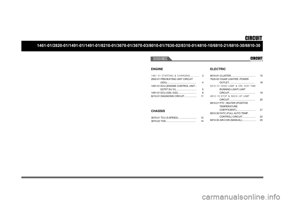
CIRCUIT
1461-01/2820-01/1491-01/1491-01/8210-01/3670-01/3670-03/8010-01/7630-02/8310-01/4810-10/6810-21/6810-30/6810-30
CIRCUIT
ENGINE
CHASSIS3670-01 TCU (5-SPEED)............................
3670-03 TOD.............................................
ELECTRIC8010-01 CLUSTER.....................................
7630-02 CIGAR LIGHTER, POWER
OUTLET......................................
8310-01 HEAD LAMP & DRL (DAY TIME
RUNNING LIGHT) UNIT
CIRCUIT.......................................
4810-10 STOP & BACK-UP LAMP
CIRCUIT.......................................
6810-21 PTC HEATER (POSITIVE
TEMPERATURE
COEFFICIENT).............................
6810-30 FATC (FULL AUTO TEMP.
CONTROL) CIRCUIT....................
6810-30 AIR-CON (MANUAL)..................... 12
1415
18
19
20
21
22
25 1461-01 STARTING & CHARGING............
2820-01 PREHEATING UNIT CIRCUIT
(XDi))............................................
1491-01 ECU (ENGINE CONTROL UNIT -
D27DT EU IV)...............................
1491-01 ECU (GSL G32)............................
8210-01 DIAGNOSIS CIRCUIT...................3
4
5
8
11
Page 187 of 465
0-14
RODIUS 2006.09
8710-01
STICS
(3) Speed Sensitive INT (Intermittent) Wiper
For STICS without rain sensor, perform the following operation:
1. Controls the wiper intermittent operation by the values from vehicle speed and volume.
Calculates and converts the Intermittent interval automatically by using the vehicle speed
and INT VOLUME when the ignition switch is in “ON” position and the INT switch is in
“ON” position (the engine is running).
The wipers are operated in vehicle speed sensitive mode when turning the INT switch
to “ON” position with the engine running or starting the engine with the INT switch
positioned “ON”.
Intermittent interval (at 0 km/h): 3 ± 0.5 ~ 19 ± 2 seconds -
-
-
2. Vehicle speed calculation
[Input the vehicle speed]
It is calculated by the numbers of input pulses for one second.
1 [pulses/sec] = 60 [km/h] x 60 [sec] / 637 pulses = 1.41 [km/h]
3. VOLUME calculation
Calculates the INT VOLUME with 5 grades as shown in the table in next page. -
4. Pause time calculation
Pause time: the duration that wipers are stopped at parking position
Elapsed time: the duration after the wiper motor started to operate from parking position
The pause time is calculated by the vehicle speed and VOLUME value as shown in the
table in next page. -
-
-
If the pause time is below 1.0 second, the wipers operate without pause.
If the pause time is over 1.5 seconds, the wipers operate intermittently. ·
·
Page 212 of 465
0-39
STICS
RODIUS 2006.09
8710-01
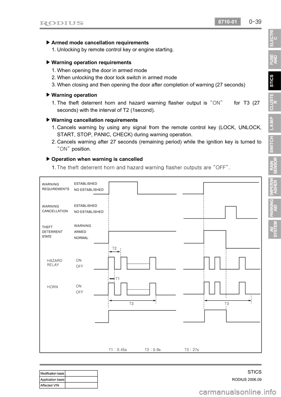
Armed mode cancellation requirements ▶
Unlocking by remote control key or engine starting. 1.
Warning operation requirements ▶
When opening the door in armed mode
When unlocking the door lock switch in armed mode
When closing and then opening the door after completion of warning (27 seconds) 1.
2.
3.
Warning operation ▶
The theft deterrent horn and hazard warning flasher output is “ON” for T3 (27
seconds) with the interval of T2 (1second). 1.
Warning cancellation requirements ▶
Cancels warning by using any signal from the remote control key (LOCK, UNLOCK,
START, STOP, PANIC, CHECK) during warning operation.
Cancels warning after 27 seconds (remaining period) while the ignition key is turned to
“ON” position. 1.
2.
Operation when warning is cancelled ▶
<007b008f008c0047009b008f008c008d009b0047008b008c009b008c00990099008c0095009b0047008f009600990095004700880095008b0047008f008800a100880099008b0047009e00880099009500900095008e0047008d00930088009a008f008c00
9900470096009c009b0097009c009b009a004700880099008c> “OFF”. 1.
Page 243 of 465
0-7
RAIN SENSOR
RODIUS 2006.09
8610-11
4. FUNCTIONS OF RAIN SENSOR
1) Windshield Glass and Coupler Attachment
Check the outer windshield surface of sensing area for wear, damage and scratch. The sensor
is able to compensate the wear up to a specific level. Check the coupler attached surface of
windshield for porosity. If the porosity exists, the sensor cannot function properly.
2) Recognition of AUTO Mode
3) Instant Wipe Function
When the variable resistance knob on the multifunction wiper switch is turned by each 1 stage
from low sensitivity (Smark) to high sensitivity (F mark), the wiper operates one cycle.
And, the wiper also operates during raining up to 5 minutes after rain stops.When the engine is started with the wiper switch “AUTO” position, the wiper operates
one cycle to remind a driver that the wiper switch is in “AUTO” position.
When the wiper switch is turned to “AUTO” from OFF, the wiper operates one cycle. It
always operates one cycle for the initial operation, however, the wiper does not operate
afterwards to prevent the wiper blade wear if not raining when turning the wiper switch to
“AUTO” from “OFF”. However, the wiper operates up to 5 minutes after rain stops.
If this function does not occur, check No. 2 terminal on the rain sensor. If any defective
cannot be found, check the wiper relay (LOW) for defective. 1)
2)
3)If the installed wiper brushes are out of specification (size and length), the rain sensing
area cannot be fully wiped. In this case, the rain sensor’s sensitivity could be
decreased and the wipers are not properly operated -
As described, the STICS recognizes the wiper switch “AUTO” position. If there are not
any problem, go to diagnosis mode in STICS and check the terminal that receives signal
from wiper and communication lines between rain sensor unit and STICS. -
Page 343 of 465
0-4
RODIUS 2006.09
4892-01
ABS SYSTEM
2. GENERAL INFORMATION
The aim of the ABS is to mmaintain steerability and driving stability and to take the burden off
the driver. If the stopping distance is shorter on some road surfaces (carriageway conditions),
this is a gift of physics and not a development aim.
ABS is a device which senses that one or more of the wheels are locking up during braking. It
monitors the rotational speeds of the wheels and reduces hydraulic pressure to any wheel it
senses locking up. It is controlled by both mechanical and electronic components. When you
apply the brakes, the ABS will regulate the flow of brake fluid being delivered to the brake
calipers. By the use of electronic computers, the brakes rapidly alternate (at a rate of 30 times
per second) from full pressure to full release.
1) DRIVING PHYSICS
To give you a better understanding of the tasks and functions of ABS, we will first look at the
physics principles.
(1) The Stopping Distance
The stopping distance depends on the vehicle weight and initial speed when braking starts.
This also applies for vehicle with ABS, where ABS always tries to set an optimum brake force
on each wheel. As great forces are exerted between the tires and the carriageway when
braking, even with ABS the wheels may scream and rubber is left on the road. With an
ABS
skid mark one may be able to clearly recognize the tire profile. The skid mark of an ABS vehicle
does not however leave any hint of the speed of the vehicle in the case of an accident, as it can
only be clearly drawn at the start of braking.
(2) Brake Force on a Wheel
The maximum possible brake force on a wheel depends on the wheel load and the adhesion
coefficient between tire and carriageway. With a low adhesion coefficient the brake force, which
can be obtained is very low. You are bound to know the result already from driving on winte
r
roads. With a high adhesion coefficient on a dry road, the brake force, which can be obtained,
is considerably higher. The brake force, which can be obtained, can be calculated from below
formula: