air filter SSANGYONG RODIUS 2012 Service Manual
[x] Cancel search | Manufacturer: SSANGYONG, Model Year: 2012, Model line: RODIUS, Model: SSANGYONG RODIUS 2012Pages: 715, PDF Size: 79.36 MB
Page 149 of 715

01-70000-00
1) Service Interval
DescriptionDaily
inspectionWeekly
inspectionService interval
Engine oil & oil
filterInspection - EU Change every 20,000 km or 12
months (The service interval should
be shortened under severe
conditions)
General Change every 15,000 km or 12
months (The service interval should
be shortened under severe
conditions)
Coolant Inspection - Change every 200,000 km or 5 years
Air cleaner
element- Inspection Diesel EU Change every 20,000 km
(The service interval should
be shortened under severe
conditions)
General Change every 15,000 km
(The service interval should
be shortened under severe
conditions)
Gasoline Clean every 15,000 km, replace every
60,000 km (The service interval should
be shortened under severe
conditions)
Fuel filter - - EU Change every 40,000 km (Draining
water from fuel filter: whenever
replacing the engine oil)
General Change every 45,000 km (Draining
water from fuel filter: whenever
replacing the engine oil)
Page 155 of 715

01-130000-00
T/C oil supply pipe M6(to block) 1 10±1.0Nm -
M6
(to turbocharger)1 17±2.0Nm-
T/C oil return pipeM6×16(to block)2 10±1Nm -
M6×16
(to turbocharger)210±1Nm -
EGR valveM8×223 25±2.5Nm -
EGR pipe bolt
(to exhaust manifold)M8×16 2 10±1Nm -
EGR pipe bolt
(to EGR cooler)M8×16 2 25±2.5Nm -
Name SizeNumbers of
fastenerTightening torque
(Nm)Note (total
tightening
torque)
Hot water inlet pipeM6×12210±1Nm-
AlternatorM10×901(LO) 25±2.5Nm -
M10×1161(HI) 46±4.6Nm -
Air conditioner
compressorM8×854 25~2.5Nm -
Air conditioner bracketM6×25410±1Nm-
Intake manifoldM8×35225±2.5Nm-
M8×110625±2.5Nm-
Oil filter moduleM8×40625±2.5Nm-
M8×20125±2.5Nm-
M8×140225±2.5Nm-
Knock sensorM8×28220±5Nm-
Camshaft position
sensorM8×141 10~14Nm -
T-T-MAP pressure
sensorM6×20110±1Nm-
Exhaust manifold M8 1040±4Nm-
Turbocharger M8 325±2.5Nm-
T/C support bolt M8 125±2.5Nm-
Page 213 of 715

03-92210-01
Device for high pressure
Device for low pressure
3) DI Engine Fuel System Pressure Test
(1) Test device (Tool kit)
(2) Pre-check
Check-tighten fuel supply line
Check fuel level in fuel tank
Check air in fuel supply line (bubble in fuel supply line or fuel)
Check fuel supply line for leaks (low pressure and high pressure)
Check that specified fuel is used
Check fuel filter for contamination -
-
-
-
-
-
Page 218 of 715

03-14
(6) Low Pressure System Pressure Test
Inspection procedure ▶
All wirings/connectors and fuel lines should
be connected and the engine should work
properly.
Prepare a special tool for low pressure test
and clean it thoroughly to prevent foreign
materials from entering. 1.
2.
Disconnect the key connector for fuel filter connection, and connect both connectors to the
fuel filter and hose. 3.
Start the engine and check visually for clogged low pressure fuel system, excessive air or air
entry.
If the fuel flow is not sufficient or air is in the fuel, repair the leak area. 4.
5.
Page 231 of 715

04-31719-00
1. SPECIFICATIONS
Shorten the service interval under severe conditions such as driving on a dusty road or off-
road. *
Unit Description Specification
Air cleaner elementFilter type Dry, filter element
Initial resistance Max. 300 mmAq
Service interval EU: Change every 20,000 km
GEN: Change every 15,000 km
Air cleaner assemblyWeight 2.36kg
Operating temperature-30 ~ 100℃
IntercoolerRadiation over 13,000 Kcal
Pressure loss at turbocharger below 90 mmHg
Cooling type Air cooled type
Core size 450W*130H*70T
Core type C/FIN
Page 250 of 715

06-91914-01
Turbine Side: Inflow of foreign materials from engine
Compressor Side: such as air filter, muffler and nut 3.
Page 323 of 715

14-132412-02
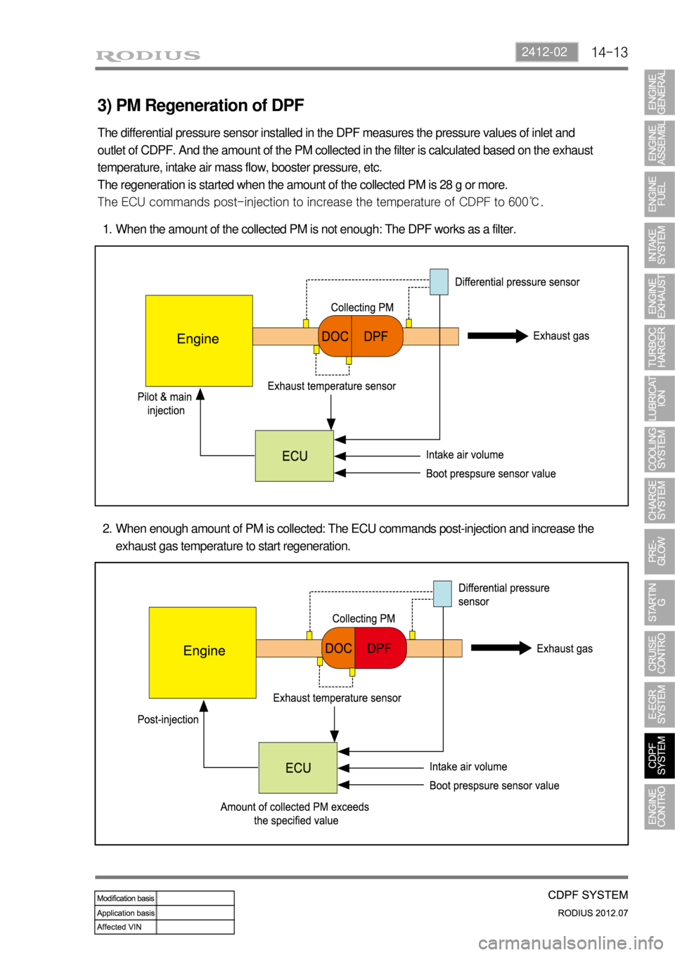
3) PM Regeneration of DPF
The differential pressure sensor installed in the DPF measures the pressure values of inlet and
outlet of CDPF. And the amount of the PM collected in the filter is calculated based on the exhaust
temperature, intake air mass flow, booster pressure, etc.
The regeneration is started when the amount of the collected PM is 28 g or more.
<007b008f008c0047006c006a007c0047008a00960094009400880095008b009a004700970096009a009b0054009000950091008c008a009b0090009600950047009b0096004700900095008a0099008c0088009a008c0047009b008f008c0047009b008c00
940097008c00990088009b009c0099008c00470096008d0047>CDPF to 600℃.
When the amount of the collected PM is not enough: The DPF works as a filter. 1.
When enough amount of PM is collected: The ECU commands post-injection and increase the
exhaust gas temperature to start regeneration. 2.
Page 326 of 715

14-16
7. CAUTIONS
1) Designated Engine Oil for CDPF (Low Ash Oil)
Need to use the designated engine oil for CDPF 1.
The smoke from the vehicle may generate the particle material in the ambient air. CDPF is
the device to reduce the smoke by collecting and recycling it. To ensure the performance
of CDPF, the designated engine oil should be used.
The smoke including combusted sulfur in fuel cannot be recycled in CDPF. This smoke
generates the ash, resulting in clogging the filter. -
-
Advantages when using the designated engine oil for CDPF 2.
Reduces the amount of ash
Improves the fuel economy and reduces the CO2
Increases the life span of engine oil
Available for all engines (diesel and gasoline) -
-
-
-
Problems when using non-designated engine oil for CDPF 3.
Decreases the life span of engine oil due to accumulated ash in DPF (around 30%)
Decreases the fuel economy due to friction resistance, exhaust gas resistance and
frequent recycling process of DPF -
-
The fuel containing high sulfur may cause the same problems.
Page 657 of 715

01-2
Front air conditioner module assembly - inside instrument panel
Compressor - engine rightAQS/Air source selection
switch
Sun load sensor - instrument
panel upper left
1. SYSTEM LAYOUT AND COMPONENTS
Type Air cindotioner controller
FATC
Manual air
conditioner
It change sun load coming through
front windshield into current to input to
FATC controller. *
Air mix door
actuator
PTC (If equipped)
Duct temperature
sensor
Mode door
actuator
Air conditioner wiring
Thermo AMP
Air source door
actuator
Air conditioner
filter
Bloewr motor
Blower high speed relayPower transistor
Page 661 of 715

01-6
2) AIR CONDITIONER MODULE WIRING AND LAYOUT
(1) Front Air Conditioner Module
Air source selection
door actuator
Air conditioner
filterEvaporator
Blower motor
Blower high
speed relay
Heater core
Wiring layout
Components